EP0426448A2 - Vorrichtung für Würfelspiel - Google Patents
Vorrichtung für Würfelspiel Download PDFInfo
- Publication number
- EP0426448A2 EP0426448A2 EP90311920A EP90311920A EP0426448A2 EP 0426448 A2 EP0426448 A2 EP 0426448A2 EP 90311920 A EP90311920 A EP 90311920A EP 90311920 A EP90311920 A EP 90311920A EP 0426448 A2 EP0426448 A2 EP 0426448A2
- Authority
- EP
- European Patent Office
- Prior art keywords
- die
- dice
- game board
- game unit
- casting
- Prior art date
- Legal status (The legal status is an assumption and is not a legal conclusion. Google has not performed a legal analysis and makes no representation as to the accuracy of the status listed.)
- Granted
Links
Images



Classifications
-
- A—HUMAN NECESSITIES
- A63—SPORTS; GAMES; AMUSEMENTS
- A63F—CARD, BOARD, OR ROULETTE GAMES; INDOOR GAMES USING SMALL MOVING PLAYING BODIES; VIDEO GAMES; GAMES NOT OTHERWISE PROVIDED FOR
- A63F9/00—Games not otherwise provided for
- A63F9/04—Dice; Dice-boxes; Mechanical dice-throwing devices
Definitions
- This invention relates to an apparatus for playing dice games, and more particularly to a dice game unit for playing games by casting a die adapted to indicate a particular number of spot(s) on the top thereof after being cast onto a game board.
- Dice games are usually conducted by a player by manually casting dice.
- the dice games there are known dice poker for playing games by casting four to six pieces of dice, for example, onto a game board, and a game called "Big & Small” for playing games by casting two dice onto a game board.
- United States Patent No. 4,909,513 discloses an automatic playing machine for playing dice games such as dice poker by casting a plurality of dice each having a magnet mounted therein into a magnetic field, which is based on the principle that dice each having a magnet mounted therein are cast into a strong magnetic field and each of the dice indicates a predetermined number of spot(s) on the top thereof.
- the plurality of dice have to be controlled individually, the construction of the machine is complicated, and the operations of casting dice onto the game board to allow each of them to indicate a particular number of spot(s) on the top thereof and recovering them become complicated.
- the present invention has been made in view of the above-mentioned circumstances and has for its object to provide a dice game unit for selecting one piece of die and casting it on a game board by a very simple mechanism.
- a dice game unit for playing games by casting a die having a magnet mounted therein and adapted to indicate a particular number of spot(s) on the top thereof after being cast onto a game board arranged to generate a magnetic field, comprising means for casting a die onto a game board; means for recovering the die which has been cast on the game board; die receiver for receiving the recovered die; and means for conveying the dice, characterized in that said dice conveying means comprises a conveying member having holding plates mounted at plurality of places thereon, each of the die holding plates is arranged to be opened and closed so that it may seize a die from the die receiver.
- a die adapted to indicate a predetermined number of spot(s) on the top thereof after being cast can be cast onto the game board.
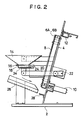
- Figs. 1 and 2 show the overall construction of one embodiment of the present invention.
- Fig. 1 is a front view of the embodiment
- Fig. 2 is a side elevational view of the same.
- a support base 2 has a supporting plate 4 mounted thereon.
- a dice conveyor belt 8 is wound around rollers 6A, 6B and 6C mounted on the support plate 4 and is rotatively driven by a motor 10.
- a plunger 12 mounted on the support plate 4 above the rollers 6A, 6B installed in juxtaposition is a plunger 12 serving as a die casting means.
- the die casting means is not to be limited to this type, it is possible to cast a die onto a game board by pulling a spring actuated lever, or eject a die by turning the lever or by means of a mechanism in which the principle of leverage is applied.
- a die ejected by the plunger 12 is cast into a game board 14 supported by the support plate 4.
- a bottom plate 16 is provided below the game board 14, and a magnet 18 is located under the bottom plate 16. Since the game board 14 is then applied with a magnetic field generated by the magnet 18 below the bottom plate 16, the die having a magnet mounted therein is controlled in posture and rests on the bottom plate 16 indicating a predetermined number of spot(s) on the top thereof.
- the bottom plate 16 and the magnet 18 are connected through the intermediary of a crank member 20 to a motor 22 for die recovery purposes.
- the arrangement is made such that when the motor 22 for die recovery purposes is driven the bottom plate 16 and the magnet 18 are turned about a shaft 24 so as to drop the die resting on the bottom plate 16 and then returned to their original positions. While, in this embodiment, the bottom portion is arranged to be turned to drop the die, it may be slidably moved instead, or alternatively, an arrangement wherein a portion of the peripheral wall of the game board member 14 on the bottom plate is movable so as to drop the die may be utilized.
- the die which has dropped will tumble along a die recovery guide 26 down onto a bowl-shaped die receiver 28.
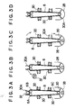
- Figs. 3A-3D show the detailed construction of the dice conveyor belt 8 and the operation thereof.
- the dice conveyor belt 8 is provided with die holding plates 30 at six places thereof, and each of the holding plates 30 can be opened and closed.
- the die holding plates 30 are adapted to hold six dice each having a magnet mounted therein, and being adapted to indicate a predetermined number of spot(s) from 1 to 6 under the influence of the magnetic field when each of them is cast on the game board 14.
- a die 32 adapted to indicate "one spot” on the top thereof after it is cast is illustrated showing "one spot” and being held by a holding plate 30A in Fig. 3(A).
- the number of spot(s) shown in the front view is not limited to one, and any of the number of spot(s) from 1 to 6 is acceptable.
- the die 32 adapted to indicate "one spot" on the top thereof after being cast onto the game board is located at the uppermost position and the plunger 12 is supplied with electricity, then the die 32 is ejected by the plunger 12 as shown in Fig. 3(B) towards the game board 14 and rests thereon indicating "one spot” on the top thereof under the influence of the magnetic field applied to the game board 14, as aforementioned.
- the holding plate 30A which was holding the die 32 will go through the condition as shown in Fig. 3(C) and stop at a position opposite to the die receiver 28 and open fully to facilitate the recovery of the die 32 and stand by, as shown in Fig. 3(D).
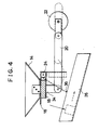
- the bottom plate 16 rests on the magnet 18 which is mounted on a magnet mounting plate 34.
- the bottom plate 16 and the magnet mounting plate 34 are pivotally mounted on the shaft 24 so that they may be turned independently.
- the magnet mounting plate 34 is connected to and hold by the die recovery motor 22 through the intermediary of the crank member 20.
- the magnet mounting plate 34, the magnet 18 mounted thereon and the bottom plate 16 resting on the magnet 18 are turned as an integral unit about the shaft 24 by the horizontal movement of the crank member 20, which is caused by rotation of the motor 22, the die 32 on the bottom plate 16 will drop since the turning radius of the bottom plate 16 is larger than those of the magnet 18 and the magnet mounting plate 34, the turning of the bottom plate 16 is stopped by a stopper 36 secured fixedly to the die recovery guide 26, whilst the magnet 18 and the magnet mounting plate 34 keep turning.
- the influence of the magnetic field applied by the magnet 18 onto the die 32 will reduce so that the die 32 will drop smoothly on the die recovery guide 26.
- the dice conveyor belt 8 has die selective reflector plates 40 mounted thereon, each of which is located at a predetermined, fixed position from each of the holding plates 30.
- the arrangement is made such that by stopping the dice conveyor belt 8 when the die selective reflector plate 40 has traversed the sensor 42 the die holding plate 30 can be stopped either at the uppermost position or at the lowermost position.
- a reference point reflector plate 44 which is longer than the die selective reflector plates 40, is mounted at one place on the dice conveyor belt 8, and a sensor 46 for detecting the reference point reflector plate 44 is installed in juxtaposition to the sensor 42. According to such arrangement, since the reference point reflector plate 44 traverses the sensors 42, 46, which are of reflection type photosensors, at the same time, the location of the reference point can be detected.
- the dice conveyor belt 8 can be stopped when a die adapted to indicate a designated number of spot(s) on the top thereof after being cast is located either at the die casting position or at the die receiving position.
- the game unit "Big & Small” is used for playing games to guess the sum of the number of spot(s) appearing on the top of two dice after being cast on a game board is larger or smaller than 7. If the sum is 7, the player loses a game. The following rule is established to give enjoyment to games.
- This game is called “Snake Eyes", and there are provided three betting buttons, “Big”, “Small” and “Snake Eyes” (in case both dice indicate “1” and “1", respectively). But, the player is allowed to bet one of the three places. In case the Snake Eye ("1" and “1") appears, 30 times as much as a bet is paid to the player. The pay-off rate when the sum is smaller or bigger than 7 is 0.8334.
- Fig. 6 is a perspective view showing a game machine "Snake Eyes" 50.
- Two game boards 42A and 52B, in each of which a die is cast, are designed like eyes of a snake.
- the spot of "1" on each of dice is indicated in bigger size and in red with a fluorescent paint.
Landscapes
- Engineering & Computer Science (AREA)
- Multimedia (AREA)
- Pinball Game Machines (AREA)
- Toys (AREA)
Applications Claiming Priority (2)
| Application Number | Priority Date | Filing Date | Title |
|---|---|---|---|
| JP1286419A JPH0632701B2 (ja) | 1989-11-02 | 1989-11-02 | ダイスゲームユニット |
| JP286419/89 | 1989-11-02 |
Publications (3)
| Publication Number | Publication Date |
|---|---|
| EP0426448A2 true EP0426448A2 (de) | 1991-05-08 |
| EP0426448A3 EP0426448A3 (en) | 1991-12-11 |
| EP0426448B1 EP0426448B1 (de) | 1993-12-29 |
Family
ID=17704147
Family Applications (1)
| Application Number | Title | Priority Date | Filing Date |
|---|---|---|---|
| EP90311920A Expired - Lifetime EP0426448B1 (de) | 1989-11-02 | 1990-10-31 | Vorrichtung für Würfelspiel |
Country Status (4)
| Country | Link |
|---|---|
| US (1) | US5031913A (de) |
| EP (1) | EP0426448B1 (de) |
| JP (1) | JPH0632701B2 (de) |
| DE (1) | DE69005590T2 (de) |
Cited By (1)
| Publication number | Priority date | Publication date | Assignee | Title |
|---|---|---|---|---|
| EP0701849A3 (de) * | 1994-09-19 | 1997-08-27 | Sega Enterprises Kk | Spielvorrichtung mit einem Körper dessen Bewegung ein Ergebnis eines Spieles bestimmt |
Families Citing this family (20)
| Publication number | Priority date | Publication date | Assignee | Title |
|---|---|---|---|---|
| US5263715A (en) * | 1992-10-05 | 1993-11-23 | Irem Corporation | Dice displaying apparatus for a computer game machine |
| BE1010950A3 (nl) * | 1997-02-27 | 1999-03-02 | Elaut Nv | Teerlingspelautomaat. |
| US6173955B1 (en) | 1998-12-22 | 2001-01-16 | Mikohn Gaming Corporation | Poker dice casino game method of play |
| US6338678B1 (en) * | 1999-08-23 | 2002-01-15 | Atlantic City Coin & Slot Service Company, Inc. | Ball selector and display device for use with gaming devices |
| US7258610B2 (en) * | 2000-03-23 | 2007-08-21 | Atlantic City Coin & Slot Service Company, Inc. | Gaming device with transport device and method of use |
| US8869177B2 (en) * | 2007-09-06 | 2014-10-21 | International Business Machines Corporation | Decoupling components of a software system at compile time and load time |
| US8929550B2 (en) | 2013-02-01 | 2015-01-06 | Department 13, LLC | LPI/LPD communication systems |
| US20070243923A1 (en) * | 2004-07-22 | 2007-10-18 | Atlantic City Coin & Slot Service Company, Inc. | Progressive gaming system and method of use |
| US7572185B2 (en) * | 2004-10-01 | 2009-08-11 | Atlantic City Coin & Slot Service Company, Inc. | Gaming device with animated figure and movable object display |
| JP4580742B2 (ja) * | 2004-11-30 | 2010-11-17 | 任天堂株式会社 | ゲームプログラムおよびゲーム装置 |
| CA2681744A1 (en) * | 2006-03-23 | 2007-09-27 | Altius Games Inc. | Three dimensional game and method |
| US7780166B1 (en) * | 2006-06-01 | 2010-08-24 | Big Monster Toys, Llc | Game having an electronic instruction unit with a mechanical die agitator |
| US8351701B2 (en) * | 2008-04-21 | 2013-01-08 | Tien-Shu Hsu | Method for recognizing dice dots |
| US20150343303A1 (en) * | 2014-05-28 | 2015-12-03 | Douglass A. HILL | Random number generator |
| US10366563B2 (en) | 2016-08-19 | 2019-07-30 | Fresh Idea Global Limited | Electronic table game poker system and methods |
| US10598811B2 (en) * | 2017-01-25 | 2020-03-24 | Intel Corporation | Magnetic identification of an object |
| US11113932B2 (en) | 2017-08-01 | 2021-09-07 | Fresh Idea Global Limited | Electronic gaming machine supporting table games |
| US10688383B2 (en) * | 2018-10-22 | 2020-06-23 | Fresh Idea Global Limited | Gaming object flipping apparatus for electronic gaming machine |
| CN111973976B (zh) * | 2020-08-26 | 2024-12-24 | 陈灵荣 | 一种防作弊的骰子键盘及其麻将机 |
| US20220379193A1 (en) * | 2021-02-10 | 2022-12-01 | Charles E. Ankner | Universal magnetic game board including advanced reconfigurable magnetic random number generator |
Family Cites Families (4)
| Publication number | Priority date | Publication date | Assignee | Title |
|---|---|---|---|---|
| US2212736A (en) * | 1939-06-05 | 1940-08-27 | New Era Sales Machine Company | Amusement device |
| US2378722A (en) * | 1943-03-24 | 1945-06-19 | James S Nicholas | Amusement device |
| JPH01259888A (ja) * | 1987-10-05 | 1989-10-17 | Fuji Denshi Kogyo Kk | ダイスを用いた自動遊技機 |
| JPH01159889U (de) * | 1987-12-18 | 1989-11-06 |
-
1989
- 1989-11-02 JP JP1286419A patent/JPH0632701B2/ja not_active Expired - Lifetime
-
1990
- 1990-10-31 DE DE69005590T patent/DE69005590T2/de not_active Expired - Fee Related
- 1990-10-31 EP EP90311920A patent/EP0426448B1/de not_active Expired - Lifetime
- 1990-10-31 US US07/606,203 patent/US5031913A/en not_active Expired - Fee Related
Cited By (2)
| Publication number | Priority date | Publication date | Assignee | Title |
|---|---|---|---|---|
| EP0701849A3 (de) * | 1994-09-19 | 1997-08-27 | Sega Enterprises Kk | Spielvorrichtung mit einem Körper dessen Bewegung ein Ergebnis eines Spieles bestimmt |
| US5865435A (en) * | 1994-09-19 | 1999-02-02 | Sega Enterprises, Ltd. | Game apparatus using an object of which movement determines a result of a game |
Also Published As
| Publication number | Publication date |
|---|---|
| EP0426448B1 (de) | 1993-12-29 |
| DE69005590D1 (de) | 1994-02-10 |
| EP0426448A3 (en) | 1991-12-11 |
| US5031913A (en) | 1991-07-16 |
| JPH0632701B2 (ja) | 1994-05-02 |
| JPH03146082A (ja) | 1991-06-21 |
| DE69005590T2 (de) | 1994-05-19 |
Similar Documents
| Publication | Publication Date | Title |
|---|---|---|
| EP0426448A2 (de) | Vorrichtung für Würfelspiel | |
| EP1009500B1 (de) | Roulettekesselanordnung und tischeinrichtung | |
| US5226653A (en) | Multilevel play feature for a pinball game | |
| US8448948B1 (en) | Vertically arranged arcade game | |
| CA2364413A1 (en) | Device and method for continuously shuffling and monitoring cards | |
| JP2003520613A (ja) | グリッドスキルアミューズメントゲーム又は取り出し装置 | |
| US10109159B1 (en) | Arcade game with prize distribution and collection system and method | |
| TW457109B (en) | Game system for playing with medals | |
| US4979739A (en) | Ball return control apparatus | |
| JP4495548B2 (ja) | 抽選装置 | |
| EP1530175B1 (de) | Spielgerät | |
| JPS59209371A (ja) | パチンコ遊技機 | |
| JPH08126742A (ja) | パチンコ機の判定装置 | |
| EP0325687B1 (de) | Steuerungsvorrichtung für das Zurückrollen der Spielbälle | |
| JPH03193076A (ja) | パチンコゲーム機 | |
| JPH0788228A (ja) | パチンコ機の役物装置 | |
| JPH0910428A (ja) | ゲーム機における景品払出し装置 | |
| JPH09299588A (ja) | 遊技機島 | |
| JPH0249678A (ja) | パチンコ遊技機における賞球排出装置 | |
| GB2207869A (en) | Skill machines | |
| KR840000907Y1 (ko) | 자동판매기의 주화 선별장치 | |
| WO2023033912A1 (en) | Pusher amusement device with pivoting arm and game piece propulsion feature | |
| WO2001019470A2 (en) | Gaming apparatus | |
| JP2002539871A (ja) | ゲーム機 | |
| JPH07114839B2 (ja) | パチンコ機の入賞装置 |
Legal Events
| Date | Code | Title | Description |
|---|---|---|---|
| PUAI | Public reference made under article 153(3) epc to a published international application that has entered the european phase |
Free format text: ORIGINAL CODE: 0009012 |
|
| AK | Designated contracting states |
Kind code of ref document: A2 Designated state(s): DE FR GB |
|
| PUAL | Search report despatched |
Free format text: ORIGINAL CODE: 0009013 |
|
| AK | Designated contracting states |
Kind code of ref document: A3 Designated state(s): DE FR GB |
|
| 17P | Request for examination filed |
Effective date: 19920214 |
|
| 17Q | First examination report despatched |
Effective date: 19930223 |
|
| GRAA | (expected) grant |
Free format text: ORIGINAL CODE: 0009210 |
|
| AK | Designated contracting states |
Kind code of ref document: B1 Designated state(s): DE FR GB |
|
| REF | Corresponds to: |
Ref document number: 69005590 Country of ref document: DE Date of ref document: 19940210 |
|
| ET | Fr: translation filed | ||
| PLBE | No opposition filed within time limit |
Free format text: ORIGINAL CODE: 0009261 |
|
| STAA | Information on the status of an ep patent application or granted ep patent |
Free format text: STATUS: NO OPPOSITION FILED WITHIN TIME LIMIT |
|
| 26N | No opposition filed | ||
| PGFP | Annual fee paid to national office [announced via postgrant information from national office to epo] |
Ref country code: FR Payment date: 19950831 Year of fee payment: 6 |
|
| PGFP | Annual fee paid to national office [announced via postgrant information from national office to epo] |
Ref country code: GB Payment date: 19951023 Year of fee payment: 6 |
|
| PGFP | Annual fee paid to national office [announced via postgrant information from national office to epo] |
Ref country code: DE Payment date: 19951124 Year of fee payment: 6 |
|
| PG25 | Lapsed in a contracting state [announced via postgrant information from national office to epo] |
Ref country code: GB Effective date: 19961031 |
|
| GBPC | Gb: european patent ceased through non-payment of renewal fee |
Effective date: 19961031 |
|
| PG25 | Lapsed in a contracting state [announced via postgrant information from national office to epo] |
Ref country code: FR Effective date: 19970630 |
|
| PG25 | Lapsed in a contracting state [announced via postgrant information from national office to epo] |
Ref country code: DE Effective date: 19970701 |
|
| REG | Reference to a national code |
Ref country code: FR Ref legal event code: ST |