EP0426501A1 - Bewegungssteuersystem, zum Beispiel für eine Horizontalstranggiessmaschine - Google Patents
Bewegungssteuersystem, zum Beispiel für eine Horizontalstranggiessmaschine Download PDFInfo
- Publication number
- EP0426501A1 EP0426501A1 EP90312081A EP90312081A EP0426501A1 EP 0426501 A1 EP0426501 A1 EP 0426501A1 EP 90312081 A EP90312081 A EP 90312081A EP 90312081 A EP90312081 A EP 90312081A EP 0426501 A1 EP0426501 A1 EP 0426501A1
- Authority
- EP
- European Patent Office
- Prior art keywords
- encoder
- motion
- casting
- control system
- input
- Prior art date
- Legal status (The legal status is an assumption and is not a legal conclusion. Google has not performed a legal analysis and makes no representation as to the accuracy of the status listed.)
- Withdrawn
Links
- 230000033001 locomotion Effects 0.000 title claims abstract description 59
- 238000005266 casting Methods 0.000 claims abstract description 63
- 230000001276 controlling effect Effects 0.000 claims 4
- 230000002844 continuous effect Effects 0.000 claims 1
- 238000000465 moulding Methods 0.000 claims 1
- 230000006870 function Effects 0.000 abstract description 7
- 238000012544 monitoring process Methods 0.000 abstract description 4
- 238000010276 construction Methods 0.000 abstract 1
- 239000002826 coolant Substances 0.000 description 20
- 238000000034 method Methods 0.000 description 15
- 238000004519 manufacturing process Methods 0.000 description 14
- 238000009749 continuous casting Methods 0.000 description 11
- 229910000831 Steel Inorganic materials 0.000 description 6
- 239000010959 steel Substances 0.000 description 6
- 239000000956 alloy Substances 0.000 description 5
- 229910045601 alloy Inorganic materials 0.000 description 5
- 238000010438 heat treatment Methods 0.000 description 5
- 239000002184 metal Substances 0.000 description 5
- 229910052751 metal Inorganic materials 0.000 description 5
- 238000000605 extraction Methods 0.000 description 4
- 238000004886 process control Methods 0.000 description 4
- XLYOFNOQVPJJNP-UHFFFAOYSA-N water Substances O XLYOFNOQVPJJNP-UHFFFAOYSA-N 0.000 description 4
- 238000010586 diagram Methods 0.000 description 3
- 230000003287 optical effect Effects 0.000 description 3
- 230000008569 process Effects 0.000 description 3
- 230000004044 response Effects 0.000 description 3
- XKRFYHLGVUSROY-UHFFFAOYSA-N Argon Chemical compound [Ar] XKRFYHLGVUSROY-UHFFFAOYSA-N 0.000 description 2
- 230000008878 coupling Effects 0.000 description 2
- 238000010168 coupling process Methods 0.000 description 2
- 238000005859 coupling reaction Methods 0.000 description 2
- 230000009977 dual effect Effects 0.000 description 2
- 230000007246 mechanism Effects 0.000 description 2
- 238000012986 modification Methods 0.000 description 2
- 230000004048 modification Effects 0.000 description 2
- 238000007711 solidification Methods 0.000 description 2
- 230000008023 solidification Effects 0.000 description 2
- 239000007858 starting material Substances 0.000 description 2
- RYGMFSIKBFXOCR-UHFFFAOYSA-N Copper Chemical compound [Cu] RYGMFSIKBFXOCR-UHFFFAOYSA-N 0.000 description 1
- 229910052786 argon Inorganic materials 0.000 description 1
- 239000000919 ceramic Substances 0.000 description 1
- 230000008859 change Effects 0.000 description 1
- 229910052729 chemical element Inorganic materials 0.000 description 1
- 238000004891 communication Methods 0.000 description 1
- 238000001816 cooling Methods 0.000 description 1
- 229910052802 copper Inorganic materials 0.000 description 1
- 239000010949 copper Substances 0.000 description 1
- 238000011161 development Methods 0.000 description 1
- 230000018109 developmental process Effects 0.000 description 1
- 239000012530 fluid Substances 0.000 description 1
- 230000000977 initiatory effect Effects 0.000 description 1
- 238000009434 installation Methods 0.000 description 1
- 238000012423 maintenance Methods 0.000 description 1
- 239000000463 material Substances 0.000 description 1
- 239000011819 refractory material Substances 0.000 description 1
- 230000008929 regeneration Effects 0.000 description 1
- 238000011069 regeneration method Methods 0.000 description 1
- 238000005096 rolling process Methods 0.000 description 1
- 238000003860 storage Methods 0.000 description 1
- 238000012546 transfer Methods 0.000 description 1
Images


Classifications
-
- B—PERFORMING OPERATIONS; TRANSPORTING
- B22—CASTING; POWDER METALLURGY
- B22D—CASTING OF METALS; CASTING OF OTHER SUBSTANCES BY THE SAME PROCESSES OR DEVICES
- B22D11/00—Continuous casting of metals, i.e. casting in indefinite lengths
- B22D11/04—Continuous casting of metals, i.e. casting in indefinite lengths into open-ended moulds
-
- B—PERFORMING OPERATIONS; TRANSPORTING
- B22—CASTING; POWDER METALLURGY
- B22D—CASTING OF METALS; CASTING OF OTHER SUBSTANCES BY THE SAME PROCESSES OR DEVICES
- B22D11/00—Continuous casting of metals, i.e. casting in indefinite lengths
- B22D11/16—Controlling or regulating processes or operations
- B22D11/20—Controlling or regulating processes or operations for removing cast stock
-
- B—PERFORMING OPERATIONS; TRANSPORTING
- B22—CASTING; POWDER METALLURGY
- B22D—CASTING OF METALS; CASTING OF OTHER SUBSTANCES BY THE SAME PROCESSES OR DEVICES
- B22D11/00—Continuous casting of metals, i.e. casting in indefinite lengths
- B22D11/12—Accessories for subsequent treating or working cast stock in situ
- B22D11/128—Accessories for subsequent treating or working cast stock in situ for removing
- B22D11/1284—Horizontal removing
Definitions
- This invention relates to motion control systems, e.g. for a single strand or multiple strand casting system and generally to horizontal continuous casting systems.
- a supply of molten metal is provided to a tundish prior to the initiation of the casting process.
- a starter bar having a cross-section corresponding generally to that of the to-be-formed casting is inserted into the casting mold.
- a slide gate on the tundish is opened and the molten metal within the tundish flows out through the exit port into the casting mold and welds to the starter bar.
- the drive motors then initiate the desired casting motion for the casting system and the process begins.
- the motion of the casting which is forming within the casting mold comprises a series of motions in accordance with a predetermined motion profile.
- the motion profile most commonly used includes a series of short forward motions referred to as casting strokes.
- each forward motion is followed by a short reverse motion.
- a series of motion cycles occur, each of which includes a forward casting stroke followed by a brief reverse movement.
- a motion control system and a single or multiple strand horizontal continuous caster having furnace means; molds and aftercoolers; and drive means driven by an electric motor, preferably a DC torque motor.
- the motion control system comprises a closed loop control system operative upon an electric motor for each strand of the caster.
- an encoder is coupled to the output shaft of the electric drive motor.
- a sensor coupled to the encoder provides an output signal indicative of the rotational motion of the drive motor.
- a computer control system receives information and produces a series of signals corresponding to the desired motion profile or motion cycle to be used in the casting process.
- a detector system within the control loop responds to the encoder output and to a sample of the desired motion profile cam, and produces the appropriate output signal to be applied to the drive motor to achieve the desired motion.
- the output signal is amplified by a motor drive amplifier to a power level sufficient to operate the system's drive motor.
- the computer system receives information and updates the process control displays in real time on a velocity versus time profile of the drive motor.
- the system based primarily on hardware, not software, gives real-time control and is extremely rapid and accurate.
- a tundish and tundish car 1 having an interior insulated reservoir is provided having an exit port 2 usually near the bottom surface of the tundish.
- a slide gate 3 is supported in proximity to the exit or discharge port of the tundish to permit the tundish to be opened or closed as needed.
- a refractory material lines the interior of the tundish and protects the tundish structure against the molten metal supported therein.
- One or more ceramic elements or nozzles, not shown, are provided within the tundish discharge orifice to provide an appropriate interface to the remainder of the casting system.
- the mold and aftercoolers includes a surrounding cooling system which provides for a substantial flow of coolant such as water about the exterior surfaces of the mold passage.
- the mold is generally formed of copper or other metal having a high thermal conductivity.
- a fluid control system is operative upon the casting mold to provide the necessary coolant flow in and about the exterior of the mold casting passage.
- a series of support rollers 7 are arranged in a generally linear path to support and provide a rolling surface for the casting as it exits from the casting mold.
- One or more pullers with a DC torque motor 11 are operatively coupled to the emerging casting and provide the desired motion of the casting.
- a cut-off torch 8 is 10-cated downstream of the pullers which functions to cut the strands into proper lengths.
- an encoder 13 is connected to the shaft 12 of torque motor 11. This encoder is the beginning of the motion control system.
- the primary duty of the motion control system is to precisely control the DC motor pullers in order to provide precise extraction and solidification of steel during casting and to monitor and control all the hydraulic, pneumatic, and temperatures critical to proper casting conditions.
- a preferred form of the motion control system of the present invention is generally comprised of three AT type computers with an Intel 80386 architecture. In each of the AT computers are several "stand alone" single board computers dedicated to specific tasks. Each of the single board computers provides its own bus and external connections to the external components which interface to a controller card.
- the three AT type computers are named according to their primary function -
- the PCS computer preferably contains ultra-fast, high resolution (1280 x 1024) display controllers which receive information from the AT bus and update the process control displays in real time. These displays are nearly as fast as a real time oscilloscope and display velocity versus time profiles of each motor which is casting steel, i.e., one motor for each strand. This display is essential for monitoring the proper extraction and solidification of the steel during casting. Additionally, the display can be designed, as desired, to show -
- the PCS computer receives its information from an interface board which latches all of the encoder edges in both directions which is attached to the motor shaft of the drive motor for the strand being cast.
- the motor amplifier also provides a DC output proportional to the motor current. This is input to the interface board, and then converted to an actual motor torque display.
- the system utilizes Startup Cams. Thus, there can be as many as eight alloy banks of eight each which provide pre-programmed extraction and pause profiles used when first starting the cast.
- a unique feature of the system is the use of single board computers which provide dedicated control systems for very fast realtime control of a specific task.
- the cam generation and touchscreen interface provide instantaneous regeneration of cam profiles during casting.
- the digital process displays provide oscilloscope-type waveforms of velocity profiles as well as color text and bar graph information not available from an oscilloscope.
- the PLC and data acquisition computers provide all required elements for a complete system integral within the control system so that no additional equipment is required at plant installation.
- a separate monitor displays line trends of thermocouple and temperatures of casting molds, water temperatures of the coolers, and material handling equipment. This information is received through a communications link with the other two AT type computers, TS1 and TS2.
- the TS2 has one VGA (640 x 480 resolution) color display which has touchscreen capabilities so that when the graphic system display is touched, it provides control of all external system components such as pumps, solenoids, argon pressure in furnace, air pressures, water flow rates, furnace temperatures, utilities for specifying the type of equipment attached to the system, as well as the diameter of steel being produced, the specific density of the steel, and self-diagnostic routines in order to troubleshoot maintenance problems.
- VGA 640 x 480 resolution
- This computer also has single board computers for programmable logic controllers and data acquisition controllers which act as stand-alone computers on a card and receive information through a dual port RAM in order to interface to the host AT.
- a printer is also attached to TS2 for run-time logging of all events and data during casting. All thermocouples, flow rates, and events such as solenoids, pumps, and casting motor information are stored as well as communicated to the other two computers in the system.
- the TS1 is an important computer in the casting operation. It contains a stand-alone proportional-integraldifferential (PID) loop motion control computer for each casting motor.
- PID proportional-integraldifferential
- the single board computers receive through a dual port ram interface the desired velocity profile for a casting motor, and at 1 millisecond update rates precisely control the extraction and pushback for each casting stroke.
- the operator interface is also a touchscreen which provides instantaneous generation and performance of cams which can be customized according to the specific alloy to be cast.
- cams are stored in three different banks according to their function, i.e., a Custom Cam which is a single cam which allows an operator to instantaneously change any of several parameters which define a cam in order to optimize the casting profile for an alloy in experimentation; a Quick Select Cam which is eight alloy banks of eight cams in each bank which allow the operator to quickly go from any of the eight different pre-generated cams.
- a Custom Cam which is a single cam which allows an operator to instantaneously change any of several parameters which define a cam in order to optimize the casting profile for an alloy in experimentation
- Quick Select Cam which is eight alloy banks of eight cams in each bank which allow the operator to quickly go from any of the eight different pre-generated cams.
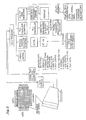
- the entire control system is generally shown in FIGURE 2.
- the encoder 13 sends pulses simultaneously to a motion controller and to an encoder and amplifier input board.
- the motion controller sends a motion command signal to amplifier which is operatively connected to puller motor.
- the amplified command signal sends a current torque output reading to the encoder and amplifier input board.
- the motion controller also sends a signal to the start-of-stroke board.
- the boards simultaneously feed to an input/output board which, in turn, provides production performance calculations which are fed to PCS programmer.
- the PCS programmer receives temperatures for trend display from the TS2 computer, best shown in FIGURE 5.
- the PCS program sends signals through the VGA color display and to a cam display for the puller motor.
- the TS1 computer menu parameters are also fed to the motion controller.
- FIGURE 3 displays in graphic form a stroke cycle of the puller motor.
- the motion is in a forward direction, followed by a short reverse motion, and then a pause before beginning the next cycle.
- a stroke period is fifteen milliseconds.
- the strand being cast is moved forward for a period of nine seconds, and is moved in reverse for three seconds, followed by a three-second pause before beginning the next stroke.
- the system simultaneously checks and adjusts at least four functions, i.e., proportional, integral, differential, and feed forward. As a result, the actual performance of the system is extremely close to the predetermine profile.
- FIGURE 4 shows a display including the commanded or computed cam curve versus actual curve or actual cam of the caster. Additionally, FIGURE 4 illustrates the sum of differences between the commanded curve versus actual curve which is defined as the following error shown in bar graph form. The display also shows the actual motor torque curve and a motor torque average bar graph. Accordingly, at all times the critical features of the casting operation are displayed.
- FIGURE 5 is a detailed illustration of the TS2 computer which provides data to the PCS program as shown in FIGURE 2.
- the computer displays simultaneously and controls parameters such as furnace temperature, water flow shutdown, billet size, and includes a menu control for the screens, keyboards, bar graphs, realtime clock, and plots data.
- FIGURE 6 sets forth a control system 10 for a multistrand horizontal continuous casting operation.
- Torque drive motor 11 includes an output shaft 12 which supports an optical encoder 13. While not shown in FIGURE 6, it should be understood that output shaft 12 is coupled to appropriate drive rollers and associated mechanisms for imparting motion to a casting strand as described in reference to FIGURE 1.
- Encoder 13 defines a conventional optical encoder having a rotary member coupled to shaft 12 and rotatable therewith.
- Encoder 13 further includes an output terminal 14 producing an output signal corresponding to the motion of shaft 12.
- a detector 30 includes a pair of input terminals 31 and 32 and an output terminal 33. Output terminal 14 of encoder 13 is coupled to input 31 of detector 30.
- Detector 30 provides a comparison of the input signals applied to inputs 31 and 32 thereof and produces an output signal at output 33 indicative of the relationship therebetween.
- a power amplifier 15 constructed in accordance with conventional fabrication techniques includes an input terminal 20 coupled to output 33 of detector 30 and an output terminal 21 coupled to motor 11. Encoder 13, detector 30, and amplifier 15 cooperate to form a proportional integral differential control loop (PID) operative upon motor 11.
- PID proportional integral differential control loop
- a second motor 40 includes an output shaft 41 coupled to an encoder 42.
- Encoder 42 is constructed in accordance with conventional fabrication techniques and includes an output terminal 43.
- a detector 50 constructed in accordance with conventional fabrication techniques includes a pair of input terminals 51 and 52 and an output terminal 53.
- An amplifier 44 constructed in accordance with conventional fabrication techniques includes an input terminal 45 coupled to output terminal 53 of detector 50 and an output terminal 46 coupled to motor 40.
- Encoder 42, detector 50, and amplifier 44 cooperate to form a PID loop operative upon motor 40.
- a motor 60 constructed in accordance with conventional fabrication techniques includes an output shaft 61 supporting an optical encoder 62.
- Encoder 62 includes an output terminal 63.
- a detector 64 includes a pair of input terminals 65 and 66 and an output terminal 67.
- An amplifier 70 constructed in accordance with conventional fabrication techniques includes an input terminal 71 coupled to output 67 of detector 64 and an output 72 coupled to motor 60.
- Encoder 62, detector 64, and amplifier 70 cooperate to form a PID loop operative upon motor 60.
- a cam storage and selection processor 100 includes a trio of output terminals 103, 104 and 105 coupled to input terminals 32, 52 and 66 of detectors 30, 50 and 64, respectively.
- a memory 101 having stored therein a plurality of digitally encoded motion profile cams is coupled to cam processor 100 by a connection 102.
- a display controller constructed in accordance with conventional fabrication techniques is coupled to cam processor 100 by a connection 106.
- a display 113 is coupled to display controller 110 by a connection 111 and a cam input device 114 is coupled to display control 110 by a connection 102.
- display controller 110 and cam processor 100 cooperate to provide a trio of casting profiles or cams which are applied to inputs 32, 52 and 66 of detectors 30, 50 and 64.
- cam processor 100 may alternatively retrieve the desired cam profiles from memory 101 or produce a specifically structured cam profile provided by the user.
- display controller 110 provides a display on display 113 of the operative cams applied to detectors 30, 50 and 64.
- a display controller 122 includes an input 123 coupled to output 14 of encoder 13, an input 124, an input 125 coupled to output 103 of cam processor 100, and an output 121.
- a display 120 is coupled to display control 122.
- a display controller 132 has an input 133 coupled to output 43 of encoder 42, an input 134, an input 135 coupled to output 104 of cam processor 100, and an output 136.
- a display 130 has an input 131 coupled to output 136 of display controller 132.
- a display controller 142 includes an input 143 coupled to output 63 of encoder 62, an input 144, an input 45 coupled to output 105 of cam processor 100, and an output 146.
- a display 140 includes an input 141 coupled to output 146 of display controller 142.
- Display controller 122 provides an appropriate set of control signals for operation of display 120.
- Display 120 in turn, in its preferred form, comprises a high resolution video display such as a raster scanner CRT.
- display control 132 provides appropriate display signals to display 130 while display control 142 provides appropriate control signals for display 140.
- a motor systems processor 80 includes an input terminal 81 coupled to output terminal 103 of cam processor 100, an input terminal 82 coupled to output terminal 14 of encoder 13, an input terminal 83 coupled to output terminal 104 of processor 100, an input terminal 84 coupled to output terminal 43 of encoder 42, an input terminal 85 coupled to output terminal 105 of cam processor 100, and an input terminal 86 coupled to output terminal 63 of encoder 62.
- Motor systems processor 80 further includes input terminals 87, 88 and 89 coupled to terminals 22, 47 and 73, respectively, of amplifiers 15, 44 and 70.
- Motor system processor 80 further includes a trio of output terminals 90, 91 and 92 coupled to inputs 124, 134 and 144 of display controllers 122, 132 and 142, respectively.
- a control system 150 which inputs information to processor 80 includes an input terminal 154 and a plurality of output terminals 151, 152 and 153.
- a coolant system 155 constructed in accordance with conventional fabrication techniques is operative upon the system casting molds (not shown) to provide the desired coolant transfer and flow through the casting molds. Coolant system 155 includes an input terminal 158 coupled to output 153 of control system 150.
- a roller control 156 is operative upon the casting system (not shown) in accordance with conventional fabrication techniques to apply a plurality of rollers to the system castings. Roller control 156 includes an input 159 coupled to output 152 of control system 150.
- a furnace heating system 157 constructed in accordance with conventional fabrication techniques and operative to heat the system furnace (not shown), includes an input terminal 160 coupled to output terminal 151 of control system 150.
- Control system 150 functions in response to input control signals applied to terminal 154 to produce the appropriate output signals communicated to coolant system 155, roller control 156 and furnace heating system 157.
- a display controller 170 includes a trio of input terminals 176, 177, and 178 coupled to output terminals 151, 152 and 153, respectively, of control system 150.
- Display controller 170 further includes a trio of input terminals 173, 174 and 175.
- Display controller 170 further includes an output terminal 172 and an output terminal 171.
- a display 180 constructed in accordance with conventional fabrication techniques includes an input terminal 181 coupled to terminal 172 of display controller 170 and an input 182.
- a printer 185 constructed in accordance with conventional fabrication techniques includes an input 187 coupled to output 171 of display controller 170.
- An input device 165 includes an output 167 coupled to input 182 of display 180, and an output 168 coupled to input 186 of printer 185.
- a casting temperature sensing system 190 includes a plurality of temperature sensing devices (not shown) for monitoring the temperature of various selected points within the casting system. Casting temperature sensor 190 includes an output 193 coupled to input 173 of display controller 170.
- a coolant flow sensor 191 includes apparatus for sensing the flow rates of coolant within coolant system 155 and includes an output 194 coupled to input 174 of display controller 170.
- a coolant temperature sensing system 192 includes a plurality of temperature sensors operative upon coolant system 155 for monitoring the coolant temperature therein at selected points within the system. Coolant temperature sensing system 192 includes an output 195 coupled to input 175 of display controller 170.
- a strip chart display 205 includes a video display and an input 206.
- a display control 200 includes an output 202 coupled to input 206 of display 205 and an input 201 coupled to display controller 170.
- cam input 114 is used by the operator to provide the appropriate signals to display control 110 and cam processor 100 to output the desired cam profiles for operation of motors 11, 40 and 60.
- input 114 may provide signals at the operator's choice which alternatively provide profile cams which are standardized and stored within memory 101 or which are custom configured for the particular alloy or metal being cast at the time.
- the output signals of cam processor 100 which consists of the three desired cam profiles for motors 11, 40 and 60 are applied to detectors 30, 50 and 64, respectively.
- the appropriate output signal is provided by detectors 30, 50 and 64 and amplified by amplifiers 15, 44 and 70, respectively, to drive motors 11, 40 and 60.
- the output of cam processor 100 is applied to display control circuits 122, 132 and 142 causing the cam profiles for motors 11, 40 and 60, respectively, to be displayed upon displays 130, 120 and 140, respectively.
- the output signals of encoders 13, 42 and 62 are similarly applied to display controllers 122, 132 and 142, respectively. The latter coupling permits the simultaneous display of the actual motion profile of motors 11, 40 and 60 upon displays 120, 130 and 140, respectively.
- displays 120, 130 and 140 are provided with information suitable for displaying both the desired cam profile and the actual resulting casting motion for each of the individual casting strands.
- amplifiers 15, 44 and 70 In addition to producing amplified drive signals for motors 11, 40 and 60, amplifiers 15, 44 and 70, respectively, each provide motor current indicative signals which are coupled to inputs 87, 88 and 89, respectively, of motor systems processor 80.
- the outputs of encoders 13, 42 and 62 as well as the desired cam profiles are similarly inputted to motor system processor 80.
- Processor 80 responds to the above-described input signals to produce performance information on each of motors 11, 40 and 60 which is coupled to display controllers 122, 132 and 142, respectively.
- display 120, 130 and 140 may display additional information regarding motor performance and caster operation.
- Control system 150 is operative to control the functions of coolant system 155, roller control system 156, and furnace heating system 157 through conventional electromechanical control mechanisms. Control system 150 responds to the input instructions received from input device 165. Thus, the operator may select the desired operations of coolant system 155, roller control system 156, or furnace heating system 157 and implement that operation directly through control system 150. Concurrently, input 165 is operative to configure display 180 to show the operation of the casting system. In its preferred form, input 165 and display 180 may be combined in the form of a touch screen display such as the presently available infra-red detecting touch screen devices.
- Display controller 170 receives information regarding the performance of coolant system 155, roller control 156, and furnace heating system 157 through the operation of casting temperature sensor 190, coolant flow sensor 191, and coolant temperature sensor 192. Display controller 170 processes the input information to produce an appropriate input signal to display controller 200. Display controller 200 in turn applies the received information to strip chart display 205.
- Strip chart display 205 includes a conventional video display terminal such as a CRT which in accordance with an important aspect of the present invention is operative to produce a display indicative of the casting system operation on a real time basis.
- strip chart display 205 includes a display having a strip chart character which is operative on a real time basis indicating system performance over a predetermined interval.
Landscapes
- Engineering & Computer Science (AREA)
- Mechanical Engineering (AREA)
- Continuous Casting (AREA)
- Control Of Electric Motors In General (AREA)
Applications Claiming Priority (2)
| Application Number | Priority Date | Filing Date | Title |
|---|---|---|---|
| US43129089A | 1989-11-03 | 1989-11-03 | |
| US431290 | 1989-11-03 |
Publications (1)
| Publication Number | Publication Date |
|---|---|
| EP0426501A1 true EP0426501A1 (de) | 1991-05-08 |
Family
ID=23711282
Family Applications (1)
| Application Number | Title | Priority Date | Filing Date |
|---|---|---|---|
| EP90312081A Withdrawn EP0426501A1 (de) | 1989-11-03 | 1990-11-05 | Bewegungssteuersystem, zum Beispiel für eine Horizontalstranggiessmaschine |
Country Status (4)
| Country | Link |
|---|---|
| EP (1) | EP0426501A1 (de) |
| JP (1) | JPH03207553A (de) |
| KR (1) | KR910009363A (de) |
| CN (1) | CN1061174A (de) |
Families Citing this family (1)
| Publication number | Priority date | Publication date | Assignee | Title |
|---|---|---|---|---|
| CN101348045B (zh) * | 2007-07-19 | 2011-12-21 | 沈阳铝镁设计研究院有限公司 | 铝锭铸造机打印装置 |
Citations (9)
| Publication number | Priority date | Publication date | Assignee | Title |
|---|---|---|---|---|
| DE2110548A1 (de) * | 1971-03-05 | 1972-09-07 | Siemens Ag | Einrichtung zum schrittweisen Ausziehen des Stranges aus der Kokille einer Stranggiessanlage |
| DE2340636A1 (de) * | 1973-08-10 | 1975-02-27 | Siemens Ag | Einrichtung zum schrittweisen ausziehen eines stranges aus einer horizontalen stranggiesskokille einer stranggiessanlage |
| EP0049238A2 (de) * | 1980-10-01 | 1982-04-07 | Böhler Aktiengesellschaft | Verfahren zur Steuerung des Strangabzuges |
| EP0052598A1 (de) * | 1980-11-18 | 1982-05-26 | Böhler Aktiengesellschaft | Vorrichtung zum horizontalen Stranggiessen |
| EP0064280A1 (de) * | 1981-05-02 | 1982-11-10 | Technica-Guss GmbH | Verfahren zum horizontalen Stranggiessen von Metallen und Stranggiessanlage hierfür |
| EP0071448A1 (de) * | 1981-07-28 | 1983-02-09 | Nippon Steel Corporation | Verfahren und Einrichtung zum Stranggiessen von Stahl |
| GB2105081A (en) * | 1981-08-26 | 1983-03-16 | Davey Lowey Limited | Monitor for continuous casting apparatus |
| US4513806A (en) * | 1983-05-23 | 1985-04-30 | Kabushiki Kaisha Kobe Seiko Sho | Apparatus for withdrawing solidified rod in horizontal type continuous casting machines |
| US4592408A (en) * | 1983-02-28 | 1986-06-03 | Manfred Haissig | Device for horizontal continuous casting of metals and alloys |
-
1990
- 1990-11-03 CN CN90109732A patent/CN1061174A/zh active Pending
- 1990-11-03 KR KR1019900017833A patent/KR910009363A/ko not_active Ceased
- 1990-11-05 EP EP90312081A patent/EP0426501A1/de not_active Withdrawn
- 1990-11-05 JP JP2299669A patent/JPH03207553A/ja active Pending
Patent Citations (9)
| Publication number | Priority date | Publication date | Assignee | Title |
|---|---|---|---|---|
| DE2110548A1 (de) * | 1971-03-05 | 1972-09-07 | Siemens Ag | Einrichtung zum schrittweisen Ausziehen des Stranges aus der Kokille einer Stranggiessanlage |
| DE2340636A1 (de) * | 1973-08-10 | 1975-02-27 | Siemens Ag | Einrichtung zum schrittweisen ausziehen eines stranges aus einer horizontalen stranggiesskokille einer stranggiessanlage |
| EP0049238A2 (de) * | 1980-10-01 | 1982-04-07 | Böhler Aktiengesellschaft | Verfahren zur Steuerung des Strangabzuges |
| EP0052598A1 (de) * | 1980-11-18 | 1982-05-26 | Böhler Aktiengesellschaft | Vorrichtung zum horizontalen Stranggiessen |
| EP0064280A1 (de) * | 1981-05-02 | 1982-11-10 | Technica-Guss GmbH | Verfahren zum horizontalen Stranggiessen von Metallen und Stranggiessanlage hierfür |
| EP0071448A1 (de) * | 1981-07-28 | 1983-02-09 | Nippon Steel Corporation | Verfahren und Einrichtung zum Stranggiessen von Stahl |
| GB2105081A (en) * | 1981-08-26 | 1983-03-16 | Davey Lowey Limited | Monitor for continuous casting apparatus |
| US4592408A (en) * | 1983-02-28 | 1986-06-03 | Manfred Haissig | Device for horizontal continuous casting of metals and alloys |
| US4513806A (en) * | 1983-05-23 | 1985-04-30 | Kabushiki Kaisha Kobe Seiko Sho | Apparatus for withdrawing solidified rod in horizontal type continuous casting machines |
Also Published As
| Publication number | Publication date |
|---|---|
| KR910009363A (ko) | 1991-06-28 |
| JPH03207553A (ja) | 1991-09-10 |
| CN1061174A (zh) | 1992-05-20 |
Similar Documents
| Publication | Publication Date | Title |
|---|---|---|
| US5316707A (en) | Injection molding apparatus control system and method of injection molding | |
| US6526360B1 (en) | Power consumption display device for machine | |
| JP3024696B2 (ja) | 射出成形機の温度制御方法 | |
| US4714102A (en) | Casting method and an apparatus therefor | |
| US5267604A (en) | Motion control system for horizontal continuous caster | |
| JP3292552B2 (ja) | 遠隔制御装置を備えた成形機制御システム | |
| EP0426501A1 (de) | Bewegungssteuersystem, zum Beispiel für eine Horizontalstranggiessmaschine | |
| EP1291149B1 (de) | Adaptives Temperaturregelverfahren und Vorrichtung für eine Spritzgiessmaschine | |
| JP7001654B2 (ja) | 射出成形機および射出成形機の表示装置の表示方法 | |
| EP1142687B1 (de) | Verfahren zur Bestimmung der Giesscharakteristiken und Spritzgiessmaschine | |
| JP2022031472A (ja) | 射出成形機、射出成形機の表示方法および射出成形機の表示装置の表示方法 | |
| JP3702819B2 (ja) | 押出成形システム | |
| JP7002516B2 (ja) | 射出成形機および射出成形機の表示装置の表示方法 | |
| EP3888876A1 (de) | Spritzgiessmaschine und industriemaschine | |
| JPH06210692A (ja) | 生産スケジュール監視機能をもつ成形機 | |
| JPS61229458A (ja) | 成形条件のモニタ方法 | |
| CN107848173A (zh) | 成型机 | |
| JP2871913B2 (ja) | 射出成形機の運転条件設定方法 | |
| JP3172957B2 (ja) | ダイカストマシンの制御盤 | |
| JPH06179232A (ja) | 射出成形機のシリンダ温度設定監視画面の表示制御方法 | |
| JP2000141019A (ja) | 表示装置を備えた成形機 | |
| JPH03207567A (ja) | 傾転式金型鋳造機 | |
| JP2996255B2 (ja) | 射出成形機 | |
| Ziemba | Use of a programmable logic controller (PLC) for temperature, position, velocity and pressure control of injection molding machinery | |
| JP2980613B2 (ja) | ダイカスト機における射出状態表示方法 |
Legal Events
| Date | Code | Title | Description |
|---|---|---|---|
| PUAI | Public reference made under article 153(3) epc to a published international application that has entered the european phase |
Free format text: ORIGINAL CODE: 0009012 |
|
| AK | Designated contracting states |
Kind code of ref document: A1 Designated state(s): AT DE FR GB IT |
|
| 17P | Request for examination filed |
Effective date: 19911029 |
|
| 17Q | First examination report despatched |
Effective date: 19940817 |
|
| STAA | Information on the status of an ep patent application or granted ep patent |
Free format text: STATUS: THE APPLICATION IS DEEMED TO BE WITHDRAWN |
|
| 18D | Application deemed to be withdrawn |
Effective date: 19960123 |