EP0427490B1 - Appareil d'entraînement de disque - Google Patents
Appareil d'entraînement de disque Download PDFInfo
- Publication number
- EP0427490B1 EP0427490B1 EP90312087A EP90312087A EP0427490B1 EP 0427490 B1 EP0427490 B1 EP 0427490B1 EP 90312087 A EP90312087 A EP 90312087A EP 90312087 A EP90312087 A EP 90312087A EP 0427490 B1 EP0427490 B1 EP 0427490B1
- Authority
- EP
- European Patent Office
- Prior art keywords
- disk drive
- housing
- drive apparatus
- circuit board
- printed circuit
- Prior art date
- Legal status (The legal status is an assumption and is not a legal conclusion. Google has not performed a legal analysis and makes no representation as to the accuracy of the status listed.)
- Expired - Lifetime
Links
Images




Classifications
-
- G—PHYSICS
- G11—INFORMATION STORAGE
- G11B—INFORMATION STORAGE BASED ON RELATIVE MOVEMENT BETWEEN RECORD CARRIER AND TRANSDUCER
- G11B33/00—Constructional parts, details or accessories not provided for in the other groups of this subclass
- G11B33/12—Disposition of constructional parts in the apparatus, e.g. of power supply, of modules
-
- G—PHYSICS
- G11—INFORMATION STORAGE
- G11B—INFORMATION STORAGE BASED ON RELATIVE MOVEMENT BETWEEN RECORD CARRIER AND TRANSDUCER
- G11B33/00—Constructional parts, details or accessories not provided for in the other groups of this subclass
- G11B33/12—Disposition of constructional parts in the apparatus, e.g. of power supply, of modules
- G11B33/121—Disposition of constructional parts in the apparatus, e.g. of power supply, of modules the apparatus comprising a single recording/reproducing device
-
- G—PHYSICS
- G11—INFORMATION STORAGE
- G11B—INFORMATION STORAGE BASED ON RELATIVE MOVEMENT BETWEEN RECORD CARRIER AND TRANSDUCER
- G11B19/00—Driving, starting, stopping record carriers not specifically of filamentary or web form, or of supports therefor; Control thereof; Control of operating function ; Driving both disc and head
- G11B19/20—Driving; Starting; Stopping; Control thereof
- G11B19/2009—Turntables, hubs and motors for disk drives; Mounting of motors in the drive
-
- G—PHYSICS
- G11—INFORMATION STORAGE
- G11B—INFORMATION STORAGE BASED ON RELATIVE MOVEMENT BETWEEN RECORD CARRIER AND TRANSDUCER
- G11B25/00—Apparatus characterised by the shape of record carrier employed but not specific to the method of recording or reproducing, e.g. dictating apparatus; Combinations of such apparatus
- G11B25/04—Apparatus characterised by the shape of record carrier employed but not specific to the method of recording or reproducing, e.g. dictating apparatus; Combinations of such apparatus using flat record carriers, e.g. disc, card
- G11B25/043—Apparatus characterised by the shape of record carrier employed but not specific to the method of recording or reproducing, e.g. dictating apparatus; Combinations of such apparatus using flat record carriers, e.g. disc, card using rotating discs
-
- G—PHYSICS
- G11—INFORMATION STORAGE
- G11B—INFORMATION STORAGE BASED ON RELATIVE MOVEMENT BETWEEN RECORD CARRIER AND TRANSDUCER
- G11B33/00—Constructional parts, details or accessories not provided for in the other groups of this subclass
- G11B33/14—Reducing influence of physical parameters, e.g. temperature change, moisture, dust
- G11B33/1446—Reducing contamination, e.g. by dust, debris
-
- G—PHYSICS
- G11—INFORMATION STORAGE
- G11B—INFORMATION STORAGE BASED ON RELATIVE MOVEMENT BETWEEN RECORD CARRIER AND TRANSDUCER
- G11B5/00—Recording by magnetisation or demagnetisation of a record carrier; Reproducing by magnetic means; Record carriers therefor
- G11B5/48—Disposition or mounting of heads or head supports relative to record carriers ; arrangements of heads, e.g. for scanning the record carrier to increase the relative speed
- G11B5/54—Disposition or mounting of heads or head supports relative to record carriers ; arrangements of heads, e.g. for scanning the record carrier to increase the relative speed with provision for moving the head into or out of its operative position or across tracks
- G11B5/55—Track change, selection or acquisition by displacement of the head
- G11B5/5521—Track change, selection or acquisition by displacement of the head across disk tracks
-
- G—PHYSICS
- G11—INFORMATION STORAGE
- G11B—INFORMATION STORAGE BASED ON RELATIVE MOVEMENT BETWEEN RECORD CARRIER AND TRANSDUCER
- G11B33/00—Constructional parts, details or accessories not provided for in the other groups of this subclass
- G11B33/14—Reducing influence of physical parameters, e.g. temperature change, moisture, dust
- G11B33/1446—Reducing contamination, e.g. by dust, debris
- G11B33/1453—Reducing contamination, e.g. by dust, debris by moisture
-
- G—PHYSICS
- G11—INFORMATION STORAGE
- G11B—INFORMATION STORAGE BASED ON RELATIVE MOVEMENT BETWEEN RECORD CARRIER AND TRANSDUCER
- G11B33/00—Constructional parts, details or accessories not provided for in the other groups of this subclass
- G11B33/14—Reducing influence of physical parameters, e.g. temperature change, moisture, dust
- G11B33/1493—Electro-Magnetic Interference [EMI] or Radio Frequency Interference [RFI] shielding; grounding of static charges
Definitions
- the present invention relates to a disk drive apparatus for providing information storage in a computer system.
- Mini-computer systems and main-frame computer systems typically employ disk drives for mass information storage.
- Such systems are not portable and are housed in large rooms having controlled environments. Consequently, the weight and space occupied by such systems are of little concern.
- the advent of personal computer systems and portable computer systems has placed a premium on providing disk drives of reduced size and weight.
- Exemplary of such a disk drive is US-A-4,712,416 which discloses a housing for containing a 95mm hard disk that provides at least ten megabytes of storage, a spindle motor for rotating the hard disk and a rotary actuator assembly for moving transducers relative to the hard disk.
- the disk drive is 171.5mm (6.75”) in length, 101.6mm (4") in width and has a height of 25.4mm (1") exclusive of a printed circuit board.
- WO 88/09551 discloses a disk drive apparatus that includes a base-plate providing a mounting surface for a spindle motor which rotates a 88.9mm (3.5") hard disk and a rotary actuator assembly which moves transducers relative to the hard disk.
- the base-plate is attached to an end-plate.
- the base-plate/end-plate assembly fits into, and establishes a seal with, an open-ended casing.
- a unitized frame attaches the end-plate/casing assembly to a printed circuit board and provides shock absorbing capability.
- the disk drive is 146.lmm (5.75”) in length, 101.6mm (4") in width and has a height of 38.lmm (1.5"). Conner Peripherals also produces a low-profile disk drive which is approximately 146.1mm (5.75") x (101.6mm (4") x 25.4mm (1"). Also known is the Model 220 disk drive produced by PrairieTek Corporation and the subject of WO 89/08313.
- the model 220 disk drive includes a housing for containing two hard disks with each providing an information storage capacity of 5-10 MBytes, a spin motor for rotating the hard disks, transducers for communicating with the hard disk, and a rotary actuator for moving the transducers relative to the hard disks.
- a printed circuit board having circuitry for controlling various components of the disk drive and the housing are attached to one another in a stacked relationship which results in an overall length of 109.2mm (4.30"), a width of 71.1mm (2.80”) and a height of 25.4mm (1.00") for the disk drive including the printed circuit board.
- spin motors have heights in the order of 15.2mm (0.6").
- Exemplary of such a spin motor is the aforementioned Model 220 disk drive produced by the assignee of the present invention.
- the rotary actuator disclosed in US-A- 471 2416 includes a triangular electromagnetic voice coil surrounded by upper and lower magnets. Surrounding the upper and lower magnets are flux return plates that are attached to the housing and constrain the magnetic fields produced by the magnets to a gap area between the magnets as well as prevent the magnetic fields produced by the magnets and the voice coil from affecting the hard disk(s). Consequently, the height of at least a portion of the rotary actuator is defined by two flux return plates, two sets of magnets and a voice coil.
- the Model 220 disk drive uses a similar arrangement.
- the rotary actuator used in the disk drive disclosed in WO 88/09551 includes an electromagnetic voice coil which surrounds a center pole.
- the center pole cooperates with a base plate and a top plate located below and above, respectively, the electromagnetic voice coil to provide flux return paths. Consequently, the height of the rotary actuator is determined by the voice coil, the center pole and the top and bottom plates.
- linear voice coil actuators that have a housing providing a surface for attaching the actuator to the disk drive housing. The actuator housing provides a flux return path as well as preventing the entry of contaminants into the disk drive housing.
- the US-A- 4, 712, 416 discloses a printed circuit board having electronics for controlling the multiple windings of the spindle motor. To attain a low profile disk drive, the printed circuit board is located in a recess located on the exterior of the base-plate and adjacent the spindle motor. Especially, the circuitry for controlling other aspects of the disk drive, like read/write control and actuator servo control, are located on another printed circuit board.
- WO 88/09551 illustrates a printed circuit board which is attached to the casing by a frame and provides electronics for controlling the hardware housed within the casing.
- the portion of the casing facing the printed circuit board appears to be devoid of any recesses. Consequently, the printed circuit board must be spaced from the casing by a distance greater than the highest profile component on the side of the printed circuit board facing the casing.
- the Model 220 disk drive piggybacks the disk drive housing on the printed circuit board.
- the portion of the housing facing the printed circuit board includes a first level defined by the spin motor and the rotary actuator, a second level recessed from the first level and a third level recessed from the second level.
- Electronic components are located on the side of the circuit board facing the housing to take advantage of the recesses defined by the second level.
- a connector for establishing a communication link between the electronics on the circuit board and a flexible circuit that extends into the housing and communicates with components contained therein is located on the side of the circuit board facing the housing and utilizes the recess defined by the third level.
- the disk drive apparatus disclosed in the above Computer Technology Review publication has a height o about 25.4 mm (1 inch) and a footprint of 71.1 mm x 109.2 mm (2.8 inches x 4.3 inches).
- a disk drive apparatus comprising:
- the present invention provides a disk drive apparatus that is especially suitable for use with computer systems where size and weight are of paramount concern.
- the preferred embodiment of the disk drive apparatus includes 63.5 mm (2.5") hard disk that preferably provides a 20 to 40 megabytes of information storage.
- the spin motor transducers for communicating with the hard disk, and the rotary actuator are contained within a housing that is approximately 101.6 mm (4.00 inches) by 69.9 mm (2.75 inches).
- the housing provides, among other things, a protected environment in which the aforementioned components can operate.
- the printed circuit board is also approximately 101.6 mm (4 inches) in length by approximately 69.9 mm (2.75 inches) in width. Due to the stacked relationship between the housing and the printed circuit board established by the frame assembly, the disk drive apparatus has an overall footprint of approximately 101.6 mm (4.0 inches) in length by approximately 71.1 mm (2.8 inches) in width. This constitutes a reduction in length over the Model 220 disk drive which has a footprint with a length of about 109.2 mm (4.3 inches)
- the present invention also provides a low profile or low height disk drive apparatus.
- the height of the disk drive apparatus is, at least in part, determined by the height of the housing.
- the height of the housing is determined by the height of the spin motor.
- the present invention which uses a spin motor having a height of approximately 8.9mm (0.35 inch) which is much less than the presently known spin motors which have heights of approximately 15.2mm (0.6 inch).
- the low profile spin motor is realized by using a magnetic material which includes a rare earth, such as neodymium or samarium, to increase the operating flux level and therefore reduce the height of the magnets within the rotor portion of the spin motor while still maintaining adequate performance characteristics.
- Another factor affecting the height of the disk drive apparatus is the various heights of the electronic components established on the printed circuit board. For instance, if all of the components are located on the side of the printed circuit board facing away from the housing, then the overall height of the disk drive apparatus will be determined by the component with the greatest height. This problem can be avoided by recessing the side of the housing which faces the printed circuit board and placing the components of greatest height on the side of the circuit board facing the housing so as to take advantage of the recesses.
- the ability to recess the housing is determined, at least in part, by the height dimension of the rotary actuator contained within the housing.
- the low profile rotary actuator allows the housing to be recessed to an extent that allows components having a height of 1.27mm (0.050") to be accommodated.
- a low profile rotary actuator can be achieved using a voice coil assembly which employs the housing as a magnetic flux return path for the magnetic fields created by the voice coil assembly. Consequently, the housing serves the following three purposes: (1) to protect or shield the components contained therein from the ambient atmosphere; (2) to provide a mounting surface for the spin motor and the rotary actuator; and (3) to act as a magnetic flux return path for magnetic fields produced by the voice coil assembly.
- a low profile rotary actuator is realised.
- a further recess can be created in the housing so that ccmponents of a height of 3.23mm (0.127") can be accommodated.
- This further recess is determined by the distance from the spin motor mounting flange to the bottom surface of the hard disk.
- Use of the recesses, as determined by the height of the low profile rotary actuator and the distance from the spin motor mounting flange to the bottom of the hard disk, to accommodate components located on the side of the printed circuit board facing the housing results, in the preferred embodiment of the invention, ina disk drive having a height dimension of approximately 1.52mm (0.6").
- the frame used to attach the housing and/or printed circuit board to the user's computer system is the frame used to attach the housing and/or printed circuit board to the user's computer system.
- the Model 220 disk drive does not use a frame. Instead, the Model 220 uses the printed circuit board to bottom mount the disk drive to the user's computer system as well as support the housing.
- the light weight of the housing and the components contained therein makes such an arrangement possible. While such a configuration reduces cost, saves space and reduces the overall size of the disk drive, it lacks shock absorbing capability, has grounding problems and does not accommodate other mounting configurations.
- the frame of the disk drive disclosed in WO 88/09551 supports both the printed circuit board and the housing The frame also provides side and bottom mounting capability together with shock absorbing capability. However, the frame has a surface area whicn requires grounding and does not provide top mounting capability.
- the disk drive produced by Conner Peripherals employs a housing having a base-plate with two side rails that provide side and bottom mounting capability
- disk drives use ambient or breather filters to prevent the entry of contaminants, like dust and dirt, into the interior of the housing.
- Exemplary of such filters are the ones employed in the Model 220 disk drive and the disk drive disclosed in US-A- 4712416 ambient or breather filters inhibit the entry of dust and dirt into the interior of the disk drive housing, they are ineffective at inhibiting the entry of water vapor. Consequently, desiccants contained within box-like structures have been placed in the interior of the housing to adsorb water vapor contained therein.
- the Model 220 disk drive uses a desiccant contained within a box-like structure.
- box-like structures creates longer diffusion paths, i.e. the distance a water molecule must travel upon entering box-like structures before adsorption occurs.
- the longer adsorption paths reduce the rate of adsorption of the desiccant.
- the frame means can comprise a frame assembly which does not require grounding, is low weight, and provides flexible mounting capability.
- the frame assembly unlike frames previously employed in disk drive apparatus, is distributed.
- the frame assembly in the preferred embodiment includes two separate but identical assemblies that attach the four corners of the housing to the four corners of the printed circuit board.
- the total surface area of the distributed frame is small enough, preferably less than five percent of the surface area of the housing, to not require grounding.
- the distributed frame assembly is extremely lightweight.
- one embodiment of the frame assembly provides the capability to top, bottom or side mount the disk drive to the user's computer system.
- the preferred embodiment of the present invention has an ambient filter assembly which inhibits the entry of water vapor from the ambient atmosphere into the housing where it can adversely affect the operation of the disk drive apparatus.
- the ambient filter assembly inhibits entry of water vapor into the interior of the housing, in contrast to known ambient filters, by employing a hole between the ambient and the interior of the disk drive, which hole creates a reaistance to the entry of water vapor into the housing.
- the resistance is created by establishing a hole having a relatively long length and/or a relatively small diameter.
- the hole has a helical or serpentine shape.
- the preferred embodiment of the present invention also an improved desiccant to adsorb moisture within the housing of the disk drive apparatus.
- Desiccants previously employed in the interiors of disk drive housings are typically in box-like structures which effectively reduce the adsorption rate of the desiccant.
- the preferred embodiment of the present invention has a compartment located between the exterior and interior surfaces of the housing to house a large, planar desiccant. The compartment is in communication with the interior of the housing. The large surface area of the planar desiccant results in an improved rate of adsorption.
- the preferred embodiment of the invention has a flex circuit geometry which results in the flex circuit applying substantially zero torque to the rotary actuator.
- the preferred embodiment of the present invention is a disk drive apparatus having dimensional characteristics that make it particularly useful in portable computer systems or computer systems where space or volume is a primary concern.
- the height dimension of the disk drive apparatus which is achieved by, among other things, reducing the height of the spin motor.
- the housing is piggy-backed on a printed circuit board that has the electronics for controlling various components of the disk drive apparatus contained within the housing.
- high profile electronic components are established on the side of the printed circuit board facing the housing to take advantage of the aforementioned recesses.
- the improved frame assembly does not require grounding and accommodates- various mounting configurations of the disk drive apparatus and, as well, provides shock mounting capability.
- An ambient filter assembly inhibits the penetration of water vapor from the ambient atmosphere into the interior of the housing.
- a desiccant that is housed in the lid of the housing.
- the large surface area of the desiccant realized by placing it in the lid of the housing results in improved rate of adsorption of water vapor present in the housing.
- an improved flex circuit geometry results in the flex circuit applying substantially zero torque to the actuator and, hence, eliminating the need for the componentry and the space required thereby to compensate for such a torque.
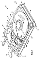
- the disk drive 20 includes a housing 22 for containing a 63.5mm (2.5") hard disk 24, a spin motor 26 for rotating the hard disk 24, a pair of transducers 28a, 28b, for communicating with the upper and lower surfaces of the hard disk 24, and a rotary actuator assembly 30 for moving the transducers relative to the hard disk.
- a ramp structure 31 for unloading and storing the transducers 28a, 28b, is also contained within the housing 22.
- the hard disk 24 is a magnetic disk capable of storing 20-40 MBytes, or even more, of information.
- the housing includes a lid 32 having a first exterior surface 34 and a first interior surface 36 located substantially parallel to the first exterior surface 34.
- the housing also includes a base plate 38 that, among other things, provides a mounting surface for several of the aforementioned components.
- the base plate 38 includes a second exterior surface 40 and a second interior surface 42 located substantially parallel to the second exterior surface 40.
- the base plate 38 is made of a magnetically conductive material, such as steel, to provide a magnetic flux return path for use in the voice coil assembly of the rotary actuator 30.
- the lid 32 is attached to the base plate 38 to form an interior space 44 that contains the aforementioned components of the disk drive apparatus 20.
- a T-shaped gasket or L-shaped gasket (not shown) is employed intermediate the lid 32 and the base plate 38 to prevent contaminants from the ambient atmosphere from entering into the interior space 44 of the housing 22 and affecting the operation of the disk drive apparatus 20.
- the lid 32 includes an ambient filter assembly 46 that inhibits contaminants, such as dust and dirt and other particulates, from entering the interior space 44 of the housing 22.
- the ambient filter assembly 46 includes a helically-shaped hole 48 that extends from the first exterior surface 34 to the first interior surface 36 and inhibits the entry of water vapor into the interior space 44 of the housing 22. Holes having other shapes that result in a hole having a length greater than the shortest distance between the first exterior surface 34 and the first interior surface 36 of the lid 32 are also possible.
- the ambient filter assembly 46 also includes a first filter 50 for inhibiting the entry of contaminants from the ambient atmosphere, such as dust and dirt and other particulates, into the interior space 44.
- the first filter 50 is located on the first interior surface 36 of the lid 32 adjacent to the helically-shaped hole 48.
- the lid 32 also includes a mounting surface 52 for an L-shaped recirculating filter 54 that utilizes the flow of air produced by the rotation of the hard disk 24 to trap contaminants, such as dust and dirt, that are within the housing 22.
- the lid 32 also includes a compartment 56 that communicates with the interior space 44 by holes 58 and houses a planar desiccant 60 that adsorbs, until it reaches an equilibrium point with the atmosphere in the interior space 44 of the housing 22, any water vapor that has entered into the interior space 44.
- First ribs 62 are also included within the compartment 56 to elevate the planar desiccant 60 from the bottom surface of the compartment and, hence, expose the entire bottom surface area of the planar desiccant 60.
- the first ribs 62 also serve to contain a second filter 64 that is located intermediate the desiccant 60 and the first interior surface 36 of the lid 32. The second filter 64 prevents any of the planar desiccant 60 from entering the interior space 44 and possibly affecting the operation of the disk drive 20.
- An exterior hatch 66 allows access to the compartment 56 during manufacturing, but is thereafter sealed.
- the large surface area of the planar desiccant 60 made possible by its location in the lid 32 improves the ability of the planar desiccant 60 to adsorb water vapor.
- the reduction in water vapor penetration of the housing 22 achieved by the helically-shaped hole 48 also reduces the amount of water vapor that the planar desiccant 60 must adsorb.
- an alternative embodiment of the ambient filter assembly 46 is illustrated.
- the alternative embodiment of the ambient filter assembly 46 is implemented by modifying compartment 56 used to house the planar desiccant 60 to include a ledge 220 having a slot 222 with a first end 224 and a second end 226.
- the lid 32 is also modified to include holes 228 that communicate with the first end 224 of the slot 222.
- the second end 226 of the slot 222 terminates adjacent to the top side of the planar desiccant 60.
- the lid 32 when in place, cooperates with the slot 222 to form a relatively long serpentine path for ambient air to enter the interior space 44 of the housing 22.
- the serpentine path also has a relatively small diameter.
- the length of the serpentine path together with its relatively small diameter inhibits the passage of water vapor from the ambient atmosphere into the interior space 44 of the housing 22. Furthermore, by locating the serpentine path in series with the planar desiccant 60, any water vapor or condensed moisture from the ambient atmosphere that has migrated from the first end 224 to the second end 226 of the slot 222 can be adsorbed by the planar desiccant 60 and thereby prevented from reaching the interior space 44 of the housing 22.
- Characteristic of the base plate 38 is its threelevel shape where each level is determined by one or more of the components contained within the housing 22.
- the first level will be considered the one farthest from the lid 32
- the third level will be the one closest to the lid 32
- the second level will be at a point intermediate the first and third levels.
- the first level is determined by the heights of spin motor 26 and the rotary actuator 30.
- the first level is defined, at least in part, by a a bottom surface of the spin motor 26.
- the spin motor 26 is mounted to the base plate 38 such that the bottom surface 67 extends through a spin motor mounting hole 68 in the base plate 38.
- the first level is also defined by a first well 70 for receiving a pivot capstan of the rotary actuator 30, and first and second reinforcing ribs 72a, 72b, that extend tangentially between the spin motor mounting hole 68 and the first well 70.
- the first and second reinforcing ribs 72a, 72b establish a triangular relationship between the spin motor mounting hole 68 and the first well 70 that reduces distortion of the base plate 38 due to the operation of the spin motor 26 or the rotary actuator 30.
- the first and second reinforcing ribs 72a, 72b reduce the time necessary for the rotary actuator 30 to position the transducers 28a, 28b, at a specific track on the hard disk 24.
- the second level is recessed from the first level by an amount determined by the height of a voice coil assembly portion of the rotary actuator 30.
- the second level is defined, at least in part, by a second well 74 and a third well 76.
- the third well 76 is located in the area bounded by the spin motor mounting hole 68, the first well 70, and the first and second reinforcing ribs 72a, 72b.
- the third level is recessed from the second level by an amount determined by the distance from the mounting flange 118 of the spin motor to the lower surface of the hard disk 24.
- the third level is defined, at least in part, by an area 78.
- When the housing 22 is assembled, it is approximately 101.6mm (4") in length and 69.9mm (2.75") in width.
- the height of the housing due to the aforementioned three-level characteristic varies between 9.7mm (0.38"), 8.6mm (0.34") and 6.9mm (0.27").
- the disk drive apparatus 20 also includes a printed circuit board 82 having an upper side 84 and a lower side 86.
- the printed circuit board is approximately 101.6mm (4") in length and approximately 69.9mm (2.75") in width.
- Electronic circuitry 88 for controlling the spin motor 26, the transducers 28a, 28b, and the rotary actuator 30 are located on the upper and lower sides 84, 86, of the printed circuit board 82. Attached to one edge of the printed circuit board 82 is a connector 90 that interfaces the electronics 88 with a first flexible circuit 92 that provides a communication path between the electronics 88 and the transducers 28a, 28b, together with the rotary actuator 30.
- the connector 90 also provides an interface between the electronics 88 and a second flexible circuit 94 that allows the electronics 88 to communicate with the spin motor 26.
- the first and second flexible circuits 92, 94 both extend from the connector 90 through gaps (not shown) between the lid 32 and the base plate 38 of the housing 22 to, respectively, the rotary actuator 30 and the spin motor 26.
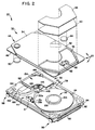
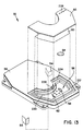
- the disk drive apparatus 20 also includes a distributed frame system 98 for attaching the housing 22 to the printed circuit board 82 in a stacked or piggyback relationship where the upper side 84 of the printed circuit board 82 faces the base plate 38 of the housing 22.
- a distributed frame system 98 for attaching the housing 22 to the printed circuit board 82 in a stacked or piggyback relationship where the upper side 84 of the printed circuit board 82 faces the base plate 38 of the housing 22.
- FIG. 5 a cross-sectional view of a portion of the distributed frame system 98 that is used to connect a corner of the housing 22 to a corner of the printed circuit board 82 is illustrated.
- the illustrated portion of the distributed frame system 98 includes a vibration isolator 100 which is made of a shock-absorbing material and located in a hole in the base plate 38 of the housing 22.
- an L-shaped mounting bracket 102 In contact with the lower surface of the vibration isolator 100 is an L-shaped mounting bracket 102 for use in attaching the disk drive apparatus 20 to the user's computer system.
- the L-shaped mounting bracket 102 includes a mounting hole 104 that allows the disk drive apparatus 20 to be side-mounted in the user's computer system.
- a spacer 106 is located intermediate the L-shaped mounting bracket 102 and the printed circuit board 82 to establish the desired clearance between the housing 22 and the printed circuit board 82.
- a ferrule 108 is in contact with the upper and interior surfaces of the vibration isolator 100.
- a screw 110 that extends through a hole defined by the ferrule 108, and corresponding holes in the L-shaped mounting bracket 102, spacer 106, and printed circuit board 82 mates with a shouldered nut 112 to connect the housing 22 to the printed circuit board 82.
- the four corners of the base plate 38 are attached to the corresponding four corners of the printed circuit board 82 in the manner illustrated in Fig. 5.
- the distributed frame system 98 provides side mounting capability as well as top and bottom mounting capability. Side mounting capability is provided by the L-shaped mounting bracket 102 which includes the side mounting hole 104. Bottom and top mounting capability can be achieved by appropriate use of the screw 110 and the shouldered nut 112.
- the alternative embodiment of the distributed frame system 98 includes a first member 196a for connecting two corners of the housing 22 to the printed circuit board 82 and an identical second member 196b for connecting the other two corners of the housing 22 to the printed circuit board 82.
- Each of the first and second members 196a, 196b includes a first connecting portion 198a and a substantially identical second connecting portion 198b that are integrally connected by a rail 200.
- the first and second connecting portions 198a, 198b each connect one corner of the housing 22 to the printed circuit board 82.
- the connecting portion 198a is described in greater detail.
- the connecting portion 198a includes an upper section 202 that is separated from a lower section 204 by a slot 206 that receives an edge of the printed circuit board 82.
- An intermediate section 208 integrally connects the upper and lower sections 202, 204.
- a horizontal hole 210 in the lower section 204 provides side mounting capability.
- the alternative embodiment of the distributed frame 98 further includes a shock absorbing element 212 located in a hole in the corner of the housing 22. The shock absorbing element 212 operatively contacts the upper section 202 of the connecting portion 198a.
- the alternative embodiment of the distributed frame system 98 further includes a snap-in connector 214 that extends through a hole defined by the shock absorbing element 212, a corresponding hole in the connecting portion 198a and a hole through the printed circuit board 82.
- the snap-in connector 214 includes clips 216 that allow it to be inserted through the aforementioned holes. However, once the clips are past the printed circuit board 82 they catch against the lower side 86 of the printed circuit board 82 to establish the connection between the housing 22 and the printed circuit board 82.
- the snap-in connector 214 also includes a flange portion 216 that contacts the upper surface of the shock absorbing element 212 once the clips 216 catch against the lower side of the printed circuit board.
- the three level base plate of the housing 22, together with the stacked relationship established by the distributed frame assembly 98 between the housing 22 and the printed circuit board 82 produces volumes between the base plate 38 and the upper side 84 of the printed circuit board that are advantageously used to achieve an overall height dimension of approximately 15.2mm (0.6") for the disk drive 20.
- the components comprising the electronics 88 are laid out on the printed circuit board 82 such that the components having heights less than or equal to a specified value are located on the lower side 86 of the printed circuit board 82.
- Components of greater height which if located on the lower side 86 of the printed circuit board 82 would add to the overall height dimension of the disk drive apparatus 20, are located on the upper side 84 of the printed circuit board 82 so as to occupy the volumes between the upper side 84 of the printed circuit board 82 and the third level of the base plate 38. While components having heights less than the specified value can be located on the lower side 86 of the printed circuit board 82, several of these components are located on the upper side 84 of the printed circuit board 82 so as to occupy the volumes between the upper side 84 of the printed circuit board 82 and the second level of the base plate 88.
- the volume extending between the upper side 84 of the printed circuit board 82 and the second level of the base plate 38 accommodates components located on the upper side 84 of the printed circuit board 82 having a nominal height of 1.27mm (0.050 inch).
- Components having a nominal height of 3.23mm (0.127inch) are located on the upper side 84 of the printed circuit board 82 to take advantage of the volume extending between the upper side 84 of the printed circuit board 82 and the third level of the base plate 38.
- Fig. 6 is a map of the upper side 84 of the printed circuit board 82 that indicates the areas where no components can be located, the areas where components having a height of 1.27mm (0.050 inch) can be located, and the areas where components having a height of 3.23mm (0.127 inch) can be located.
- the spin motor 26 preferably a brushless DC motor, used in the disk drive apparatus 20 is illustrated.
- the spin motor 26 determines the maximum height dimension of the housing 22.
- the spin motor 26 realizes a reduced height dimension, relative to known spin motors, that is used to realize an overall height dimension for the disk drive 20 of approximately 15.2mm (0.6 inch) and is described hereinafter.
- the spin motor 26 includes a base member 116 that forms the bottom of the spin motor 26 and provides a flanged portion 118 for mounting the spin motor 26 in the spin motor mounting hole 68 of the base plate 38.
- the spin motor 26 further includes a stator 120 for producing, under the control of the electronics circuitry 88, a rotating magnetic field.
- the stator 120 includes stator laminations 122 and stator windings 124, as is well known in the art, for use in producing the aforementioned rotating magnetic field.
- the stator laminations 122 and stator windings 124 are operatively connected to the base member 116.
- the spin motor 26 further includes a rotor assembly 126 that, in response to the rotating magnetic field produced by the stator 120, rotates about an axis of rotation 128.
- the rotor assembly 126 includes an outer shell 130 that has a shoulder 132 for supporting the hard disk 124.
- a clamp ring 134 is used to hold the hard disk 124 in place against the shoulder 132 of the outer shell 130.
- the clamp ring 134 is threaded to operatively engage a threaded surface on the upper, circumferential edge of the outer shell 130.
- the rotor assembly 126 also includes a rotor shaft 136 that is integral with the outer shell 130 and fits within a central opening 138 defined by the base member 116.
- First and second bearing/race assemblies 140a, 140b, are located intermediate the rotor shaft 136 and the portion of the base member 116 defining the central opening 138 to allow the rotor assembly 126 to rotate relative to the base member 116 as well as provide support.
- the rotor assembly 126 further includes twelve magnets 142a-1, each of which has a north pole face and a south pole face, that are attached to the interior surface of the outer shell 130 such that adjacent magnets have opposite poles facing the stator 120. Interaction of the magnetic fields produced by the magnets 142a-1 with the rotating magnetic field produced by the stator 120 causes the rotor assembly 126 to rotate about the axis of rotation 128. For the spin motor 126 to have a reduced height dimension relative to known spin motors, the height of the magnets 142a-1 must be reduced. Reducing the height of the magnets 142a-1, however, results in the magnets 142a-1 having an insufficient flux density when typical magnetic materials are used.
- the magnets 142a-1 are made from a material including a rare earth, such as neodymium or samarium.
- the magnets 142a-1 are made from a material that includes neodymium, boron and iron. The material is produced using a sintering process. The utilization of such materials to realize the magnets 142a-1 results in magnets h-aving a reduced height, an energy product in excess of 2.39 x 10 5 Tesla-amperes per metre (30 million gauss-oersteds) and a motor constant of approximately 5.47 x 10 5 Nm/Watt 1 ⁇ 2 (0.76 in.- oz./watt 1 ⁇ 2 ).
- magnets made from this material and having such high energy products cannot be bonded with plastic or other materials to form the torus-shaped magnetic structures typically employed in spin motors. Consequently, the magnets 142a-1 are substantially planar and are attached to correspondingly planar surfaces machined on the interior of the outer shell 130. Utilization of magnets 142a-1 results in a spin motor having a height dimension of less than 8.9mm (0.35").
- the rotary actuator assembly 30 embodies the wellknown Whitney style technology.
- the rotary actuator assembly 30 includes a pivot capstan 146 that establishes the axis of rotation for the rotary actuator assembly 30.
- the pivot capstan 146 is located in, and attached to, the base plate 38 at the first well 70.
- the rotary actuator assembly 30 further includes an arm assembly 148 that is operatively attached to the pivot capstan 146 and is substantially triangular in shape.
- the arm assembly 148 includes first and second arms 150a, 150b, for moving, respectively, first and second transducers 28a, 28b, relative to the upper and lower surfaces of the hard disk 24.
- the rotary actuator assembly 30 further includes a voice coil assembly 154 that, in response to signals from the electronics 88, causes the arm assembly 148 to rotate about the pivot capstan 146 and thereby position the transducers 28a, 28b, at a desired position over the hard disk 24.
- the voice coil assembly 154 includes an electromagnetic coil 156 that is operatively attached to the pivot capstan 146 by first and second legs 158a, 158b.
- the electromagnetic coil 156 is triangularly shaped and is wound about an axis parallel to the rotational axis of the pivot capstan 146.
- the voice coil assembly 154 further includes a voice coil magnet 160 for creating a steady-state magnetic field that is used in conjunction with a magnetic field produced by the electromagnetic coil 156 to rotate the arm assembly 148 about the pivot capstan 146.
- the voice coil magnet 160 is attached to the base plate 38 at a point below the electromagnetic coil 156.
- a post 162 limits the extent to which the arm assembly 148 can rotate in a counterclockwise direction about the pivot capstan 146.
- the post 162 includes a first or inner crash stop 164 that interacts with the first leg 158a to prevent further counterclockwise rotation of the arm assembly 148 as well as prevent damage to the rotary actuator assembly 30 by absorbing some of the rotational energy of the arm assembly 148.
- the first crash stop 164 preferably includes a leaf spring that is cantilevered or simply supported. Also included in the voice coil assembly 154 is a flux return plate 166 for providing a portion of a magnetic circuit that constrains the magnetic flux produced by the electromagnetic coil 156 and the voice coil magnet 160 to the area between the flux return plate 166 and the housing 22.
- the flux return plate extends from the top of the post 162 across the electromagnetic coil 156 and down to the base plate 38.
- the magnetic flux return plate 166 is positioned by first and second pins 168a, 168b, and held in place by the magnetic force produced by the voice coil magnet 160.
- the second crash stop 170 Attached to the magnetic flux return plate 166 is a second or outer crash stop 170 that limits the rotation of the electromagnetic coil 156 and, hence, the arm assembly 148 in the clockwise direction.
- the second crash stop 170 is made from a shock absorbing elastomeric material.
- the second crash stop 170 includes a first frusto-conical portion 172 that is inserted through a hole in the magnetic flux return plate 166 and serves to hold the second crash stop 170 in place.
- the second crash stop 170 also includes a second frusto-conical portion 174 for absorbing the rotational energy of the rotary actuator assembly 130 when it has rotated too far in the clockwise direction.
- the height of the voice coil assembly 154 determines where the second level of the baseplate 38 is located relative to the first level. Consequently, the height of the voice coil assembly 154 also determines the height of the volumes between the upper side 84 of the printed circuit board 82 and the second level of the base plate 38 and, hence, the height of the electronic components that can be located on the upper side 84 of the printed circuit board 82. In the preferred embodiment of the disk drive 20, components having a height of 1.27mm (0.050”) can be located in these volumes. This, in turn, allows an overall footprint of approximately 101.6mm (4.0") x 71.7MM (2.8”) to be attained for the disk drive 20. ' With reference to Fig. 9, the low profile features of the voice assembly 154 are illustrated.
- the base plate 38, the post 162, and the magnetic flux return plate 166 are all made of magnetically conductive materials, such as steel, and define a magnetic circuit that constrains the magnetic fields produced by the voice coil magnet 160 to the gap between the voice coil magnet 160 and the magnetic flux return plate 166. By so constraining the magnetic field produced by the voice coil magnet 160 a high torque constant for the rotary actuator 30 is realized. In addition, the magnetic fields are prevented from affecting information established on the hard disk 24.
- the reduced height of the voice coil assembly 154 is attained by using the base plate 38 as flux return path, as a mounting surface for the rotary actuator assembly 30 and the hard disk 24, and as a portion of the housing 22 that prevents contaminants from affecting the operation of the disk drive apparatus 20. Consequently, the base plate 38 serves three purposes and allows a voice coil assembly of reduced height to be realized.
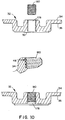
- Fig. 10 is a detailed illustration of the construction of the helically-shaped hole 48 in the ambient filter assembly 46.
- the helically-shaped hole 46 is produced by establishing a threaded hole 178 extending from the first exterior surface 34 to the first interior surface 36 of the lid 32 using an oversized tap drill.
- the threaded hole 176 is then tapped with a regular or standard size tap drill to shear off the top portions of the threads in the threaded hole 176.
- a threaded set screw 180 is then screwed into the threaded hole 176 to establish the helically-shaped hole 46 between the bottom portions of threads in the threaded hole 178 and the top portions of the threads of the set screw 178.
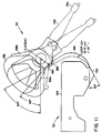
- the flexible circuit 92 includes a first portion 184 that extends from the connector 90 on the printed circuit board 82 through a gap (not shown) between the lid 32 and the base plate 38 to the second interior surface 42 of the base plate 38 where it is attached.
- the first flexible circuit 92 includes a second portion 186 having a first end 188 attached to an exterior surface 190 of the rotary actuator 30 and a second end 192 attached to the second interior surface 42 of the base plate 38.
- the first flexible circuit 92 is preferably comprised of three layers of flexible material.
- the two outer-most layers each have a thickness of approximately 2.54 x 10 -2 mm (0.001 inch) and are made of a flexible, insulating material, such as KAPTON.
- the third layer is located intermediate the two outermost layers, is also approximately 3.56 x 10 -2 mm (0.0014 inch) thick and is made of a 28.35g (one-ounce) conductive material, such as copper, with individual circuits etched in the conductive material.
- Located intermediate to each of the outermost layers and the intermediate conductive layer is an adhesive layer having a thickness of approximately 1.52 x 10 -2 mm (0.0006 inch).
- the overall thickness of the flexible circuit 92 is approximately 12.7 x 10 -2 mm (0.005 inch).
- the thickness of the flexible circuit 92 results in a relatively low flexular modulus that, in turn, reduces the ability of the second portion 186 of the first flexible circuit 92 to apply a torque to the rotary actuator 30 that would affect the position of the first and second transducers 28a, 28b, relative to the hard disk 24.
- the ability of the second portion 186 of the first flex circuit 92 to apply a torque to the rotary actuator 30 is further reduced by establishing a geometry for the second portion 186 of the first flexible circuit 92 that results in a substantially radial force being applied to the rotary actuator 30.
- the radial force in contrast to a tangential or torque producing force, does not substantially affect the position of the transducers 28a, 28b, relative to the hard disk 24.
- the geometry of the second portion 186 of the first flexible circuit 92 is best described by analyzing the problem in terms of given parameters and the boundary conditions of the first end 186 and the second end 192 of the second portion 186 of the first flexible circuit 92.
- the given parameters of the problem are the flexure modulus and the length of the second portion 186 of the flexible circuit 92.
- the relevant boundary conditions are the angle through which the rotatry actuator 30 turns and the distance from the axis of rotation to the exterior surface 190 of the rotary actuator 30 where the first end 188 is attached.
- the boundary condition relating to the second end 192 of the second portion 186 of the first flexible circuit 92 is that it must be fixed relative to the axis of rotation of the actuator 30. Given these boundary conditions, a double or S-shaped curve can be imposed upon the second portion 186 of the flexible circuit 92 that results in a substantially radial force, as determined by a free body analysis at the point of inflection between the two curves, being applied to the rotary actuator 30 through the angle in which it rotates.
- the S-shaped curve of the second portion 186 that provides substantially only a radial force on the rotary actuator 30 is determined by the position of the second end 192 of the flexible circuit 92 relative to the axis of rotation of the rotary actuator 30 for the aforementioned given parameters and boundary conditions of the first end 188 of the second portion 186 of the first flexible circuit 92. Once this point is established, the first end 188 and the second end 192 are fixed at angles that are tangential to the two curves established in the second portion 186 of the flexible circuit 92.
Landscapes
- Moving Of Heads (AREA)
- Rotational Drive Of Disk (AREA)
- Automatic Disk Changers (AREA)
Claims (8)
- Appareil d'entraînement de disque (20), comprenant:un disque dur (24);un moteur de rotation (26) pour tourner ledit disque dur (24), ledit moteur de rotation comportant une enceinte de support d'arbre (130);un transducteur (28) pour communiquer avec ledit disque dur (24);un actionneur rotatif (30) pour déplacer ledit transducteur (28) par rapport audit disque dur (24), ledit actionneur rotatif (30) comportant un cabestan de pivotement (146) et un ensemble de bobine mobile (154);un logement (22) contenant ledit disque dur (24), ledit moteur de rotation (26), ledit transducteur (28) et ledit actionneur rotatif (30) dans un intérieur de celui-ci entre un côté supérieur (34) et un côté inférieur (40) dudit logement (22), ledit logement (22) ayant une plaque de base (38);une carte de circuit imprimé (82) ayant un côté supérieur (84) et un côté inférieur;un moyen électronique (88) pour commander au moins l'un des éléments suivants:ledit moteur de rotation (26), ledit transducteur (28) et ledit actionneur rotatif (30), ledit moyen électronique (88) comportant des premier et deuxième composants situés sur ledit côté supérieur (84) de ladite carte de circuit imprimé (82);un moyen d'encadrement (98) connectant ledit logement (22) à ladite carte de circuit imprimé (82) selon une relation empilée dans laquelle ledit côté inférieur (40) du logement (22) fait face au côté supérieur (84) de ladite carte de circuit imprimé (82);dans lequel ledit appareil d'entraînement de disque (20) est caractérisé par le fait que:ledit moteur de rotation (26) est d'une hauteur inférieure ou égale à 15,2 mm (0,6 pouce); etladite plaque de base (38) dudit logement (22) a une surface principale divisée en au moins trois zones, chacune desdites au moins trois zones étant de manière générale parallèle l'une par rapport aux autres, lesdites au moins trois zones définissant des plans espacés dudit côté supérieur (34) dudit logement (22) par au moins trois distances respectives prises dans le plan perpendiculaire à la plaque de base (38), ladite enceinte de support d'arbre et ledit cabestan de pivotement définissant une partie de ladite première zone, l'espacement de ladite première zone étant défini par la hauteur dudit moteur de rotation (26), l'espacement de ladite deuxième zone étant défini par la hauteur dudit ensemble de bobine mobile (154), ladite deuxième zone étant située à côté de ladite première zone l'espacement de ladite troisième zone étant défini par la différence de hauteur entre ledit bas dudit moteur de rotation (26) et ledit disque dur (24), ladite troisième zone étant située à côté de ladite deuxième zone;ledit côté supérieur (84) de ladite carte de circuit imprimé (82) ayant des premier et deuxième ensembles de composants montés sur celui-ci, les composants dudit deuxième ensemble de composants ayant une hauteur supérieure aux composants dudit premier ensemble de composants;ledit côté supérieur (84) de ladite carte de circuit imprimé (82), sans lesdits premier et deuxième ensembles de composants, étant fourni à une position adjacente à ladite première zone, ledit premier ensemble de composants, sans ledit deuxième ensemble de composants, étant fourni sur ladite carte de circuit imprimé (82) à une position adjacente à ladite deuxième zone, et ledit deuxième ensemble de composants étant fourni sur ladite carte de circuit imprimé (82) à une position adjacente à ladite troisième zone,par lequel l'accouplement sélectif de ladite carte de circuit imprimé (82) et de ladite plaque de base (38) fournit un appareil d'entraînement de disque (20) ayant une hauteur inférieure ou égale à 16,0 mm (0,630 pouce).
- Appareil d'entraînement de disque, tel que revendiqué à la revendication 1, dans lequel:
ledit disque dur (24) a un diamètre ne dépassant pas 63,5 mm (2,5 pouces). - Appareil d'entraînement de disque, tel que revendiqué à la revendication 1 ou 2, dans lequel:
ledit appareil d'entraînement de disque (20) a un encombrement de 71,1 mm (2,8 pouces) sur 101,6 mm (4,0 pouces). - Appareil d'entraînement de disque, tel que revendiqué à la revendication 1, dans lequel:
ledit moyen électronique (88) comporte un troisième composant ou ensemble de composants situé sur ledit côté inférieur (86) de ladite carte de circuit imprimé (82), et dans lequel la hauteur dudit appareil d'entraînement de disque (20) dudit côté supérieur (34) dudit logement (22) audit côté inférieur (86) dudit troisième composant ou ensemble de composants est inférieure ou égale à 16,0 mm (0,630 pouce). - Appareil d'entraînement de disque, tel que revendiqué dans l'une quelconque des revendications précédentes, dans lequel:
ledit moteur de rotation (26) comporte un aimant réalisé dans un matériau comportant une terre rare. - Appareil d'entraînement de disque, tel que revendiqué dans l'une quelconque des revendications précédentes, dans lequel:
ledit moteur de rotation (26) comporte un aimant (142) ayant un produit d'énergie de plus de 2,39 x 10⁵ Teslampères par mètre (30 millions de gauss-oersteds). - Appareil d'entraînement de disque, tel que revendiqué dans l'une quelconque des revendications précédentes, dans lequel:
ledit côté supérieur (34) ou ledit côté inférieur (40) dudit logement (22) fournit une partie d'un chemin de retour de flux magnétique pour ledit ensemble de bobine mobile (154). - Appareil d'entraînement de disque, tel que revendiqué dans l'une quelconque des revendications précédentes, dans lequel:
ledit ensemble de bobine mobile (154) comporte un aimant (160) et une bobine mobile (156) en une relation empilée ayant une dimension de hauteur qui est inférieure à 8,9 mm (0,35 pouce).
Applications Claiming Priority (2)
| Application Number | Priority Date | Filing Date | Title |
|---|---|---|---|
| US07/432,664 US5025336A (en) | 1989-11-06 | 1989-11-06 | Disk drive apparatus |
| US432664 | 1989-11-06 |
Publications (3)
| Publication Number | Publication Date |
|---|---|
| EP0427490A2 EP0427490A2 (fr) | 1991-05-15 |
| EP0427490A3 EP0427490A3 (en) | 1992-07-08 |
| EP0427490B1 true EP0427490B1 (fr) | 1997-03-26 |
Family
ID=23717099
Family Applications (1)
| Application Number | Title | Priority Date | Filing Date |
|---|---|---|---|
| EP90312087A Expired - Lifetime EP0427490B1 (fr) | 1989-11-06 | 1990-11-05 | Appareil d'entraînement de disque |
Country Status (7)
| Country | Link |
|---|---|
| US (3) | US5025336A (fr) |
| EP (1) | EP0427490B1 (fr) |
| JP (1) | JPH03207076A (fr) |
| KR (1) | KR100235264B1 (fr) |
| AT (1) | ATE150894T1 (fr) |
| DE (1) | DE69030297T2 (fr) |
| TW (1) | TW218047B (fr) |
Cited By (1)
| Publication number | Priority date | Publication date | Assignee | Title |
|---|---|---|---|---|
| US6491741B2 (en) | 1998-10-08 | 2002-12-10 | Donaldson Company, Inc. | Filter assembly with shaped adsorbent article; and devices and methods of use |
Families Citing this family (155)
| Publication number | Priority date | Publication date | Assignee | Title |
|---|---|---|---|---|
| US5956213A (en) * | 1988-01-25 | 1999-09-21 | Seagate Technology, Inc. | Latch mechanism for disk drive using magnetic field of actuator magnets |
| WO1990003031A1 (fr) * | 1988-09-05 | 1990-03-22 | Seiko Epson Corporation | Dispositif d'enregistrement/reproduction |
| US5235482A (en) * | 1989-11-09 | 1993-08-10 | Rodime Plc | Magnetic disk drive incorporating a mechanically damped base |
| JPH0371457U (fr) * | 1989-11-13 | 1991-07-19 | ||
| JPH0636522Y2 (ja) * | 1989-11-22 | 1994-09-21 | ティアツク株式会社 | ディスクカートリッジの誤挿入防止機構 |
| US6069766A (en) * | 1990-02-09 | 2000-05-30 | Seagate Technology, Inc. | Miniature hard disc drive having low profile actuator arm voice coil and spindle motors |
| US5808838A (en) * | 1990-02-09 | 1998-09-15 | Seagate Technologies, Inc. | Miniature head disc drive system voice coil with single coil and dual stationary magnets |
| US5202804A (en) * | 1990-05-18 | 1993-04-13 | Kabushiki Kaisha Toshiba | Magnetic disk drive with a magnetic head rotationally actuated |
| KR930700935A (ko) * | 1990-06-01 | 1993-03-16 | 원본미기재 | 2.5인치 다중 디스크 드라이브 |
| US5255136A (en) * | 1990-08-17 | 1993-10-19 | Quantum Corporation | High capacity submicro-winchester fixed disk drive |
| JP2862651B2 (ja) * | 1990-08-31 | 1999-03-03 | 株式会社東芝 | 磁気ディスク装置 |
| DE69132408T2 (de) * | 1990-11-09 | 2001-01-18 | Seagate Technology Llc, Scotts Valley | Architektur für hochleistungsplattenantrieb |
| JP2922633B2 (ja) * | 1990-11-29 | 1999-07-26 | 三菱電機株式会社 | ディスク装置 |
| EP0563230B1 (fr) * | 1990-12-19 | 2000-02-16 | Mobile Storage Technology Inc. | Unite de disque dur miniature pour ordinateur portatif |
| JPH04268279A (ja) * | 1991-02-22 | 1992-09-24 | Sony Corp | ハードデイスク装置 |
| US5875067A (en) * | 1991-03-22 | 1999-02-23 | Seagate Technology, Inc. | Acoustic isolator for a disc drive assembly |
| KR960001250B1 (ko) * | 1991-06-10 | 1996-01-24 | 후지쓰 가부시끼가이샤 | 자기 디스크드라이브 |
| JP2996772B2 (ja) | 1991-07-04 | 2000-01-11 | シチズン時計株式会社 | 磁気ディスクアセンブリ装置 |
| EP0526703A3 (en) * | 1991-07-29 | 1993-03-31 | Areal Technology, Inc. | Compact disk drive useful for laptop computer |
| KR100246511B1 (ko) * | 1991-09-11 | 2000-03-15 | 토마스 에프. 멀베니 | 액추에이터 암 몸체, 액추에이터 암판 및 제어된 환경의 외부에 있는 vcm 마그네트를 포함하는 1.8인치 윈체스터 드라이브 카드 |
| US5483419A (en) * | 1991-09-24 | 1996-01-09 | Teac Corporation | Hot-swappable multi-cartridge docking module |
| US5446609A (en) * | 1991-09-24 | 1995-08-29 | Teac Corporation | Low profile disk drive assembly |
| JPH07176168A (ja) | 1991-09-24 | 1995-07-14 | Kalok Corp | 大容量薄型ディスクドライブシステム、ディスクドライブアセンブリ及び組立方法 |
| US6310747B1 (en) | 1991-09-25 | 2001-10-30 | Mobile Storage Technology, Inc. | Method for reducing external signal interference with signals in a computer disk storage system |
| US5379171A (en) * | 1991-09-25 | 1995-01-03 | Integral Peripherals | Microminiature hard disk drive |
| US5278709A (en) * | 1991-10-15 | 1994-01-11 | Areal Technology | Assembly of compact disk drive having a glass disk with a magnesium head arm assembly and a steel motor hub |
| JP2850603B2 (ja) * | 1991-11-14 | 1999-01-27 | 松下電器産業株式会社 | 磁気記録再生装置 |
| EP0918327B1 (fr) * | 1991-11-22 | 2005-06-15 | Fujitsu Limited | Entraínement de disque |
| US5270887A (en) * | 1991-12-04 | 1993-12-14 | Western Digital Corporation | Compact disk drive head disk assembly with conformable tape seal |
| DE69232757T2 (de) * | 1992-01-21 | 2003-02-06 | Fujitsu Ltd., Kawasaki | Optisches Plattengerät mit reduzierten Abmessungen |
| US5596738A (en) * | 1992-01-31 | 1997-01-21 | Teac Corporation | Peripheral device control system using changeable firmware in a single flash memory |
| US5396388A (en) * | 1992-02-27 | 1995-03-07 | Censtor Corp. | Compact, high-speed, rotary actuator and transducer assembly with reduced moment of inertia and mass-balanced structural overlap with drive motor and organizing method for the same |
| ATE166486T1 (de) * | 1992-03-10 | 1998-06-15 | Ibm | Plattenspeicherantrieb |
| US5243495A (en) * | 1992-03-20 | 1993-09-07 | Digital Equipment Corporation | Removable enclosure housing a rigid disk drive |
| US5222897A (en) * | 1992-04-01 | 1993-06-29 | Emc Corporation | Circuit board inserter/ejector system |
| JP2516162Y2 (ja) * | 1992-04-02 | 1996-11-06 | ティアック株式会社 | ディスク装置における可撓性プリント回路 |
| US5491607A (en) * | 1992-04-14 | 1996-02-13 | Abekas Video Systems, Inc. | Method of modifying a disk drive from serial to parallel operation |
| JPH0590693U (ja) * | 1992-04-27 | 1993-12-10 | 株式会社東芝 | 磁気ディスク装置の電磁遮蔽構造 |
| US5396384A (en) * | 1992-05-12 | 1995-03-07 | Quantum Corporation | Hard disk drive architecture |
| US5519270A (en) * | 1992-08-19 | 1996-05-21 | Fujitsu Limited | Spindle motor and disk drive having the same |
| US5436517A (en) * | 1992-08-24 | 1995-07-25 | Nagano Nidec Corporation | Recording disk driving apparatus |
| DE69329036T2 (de) * | 1992-09-23 | 2000-11-16 | Seagate Technology, Inc. | Formfaktor 2,5 zoll plattenantrieb niedriger höhe |
| JPH06215530A (ja) * | 1992-09-28 | 1994-08-05 | Fujitsu Ltd | ディスク記憶システム |
| BR9307256A (pt) * | 1992-10-14 | 1999-05-25 | Maxtor Corp | Fator de forma de 10 para uma unidade de disco de 2,5 polegadas |
| JP3129894B2 (ja) * | 1992-10-26 | 2001-01-31 | 富士通株式会社 | ディスク記憶システム |
| US5608592A (en) * | 1992-10-29 | 1997-03-04 | Fujitsu Limited | Head actuator |
| US5373407A (en) * | 1992-11-12 | 1994-12-13 | Mitsumi Electric Co., Ltd. | Disk drive spindle motor |
| EP0597189A3 (en) * | 1992-11-13 | 1994-09-14 | Hewlett Packard Co | Low profile rotary actuator structure for a hard disk drive. |
| WO1994011879A1 (fr) * | 1992-11-13 | 1994-05-26 | Conner Peripherals, Inc. | Unite de disques lubrifiee |
| US5357386A (en) * | 1992-11-13 | 1994-10-18 | Seagate Technology, Inc. | Disc drive with head/disc assembly having sealed connectors |
| US5307222A (en) * | 1992-11-13 | 1994-04-26 | Maxtor Corporation | Air filter and circulation system for a hard disk drive |
| JP3364969B2 (ja) * | 1992-12-18 | 2003-01-08 | ソニー株式会社 | 光磁気ディスクドライブ装置 |
| WO1994015331A1 (fr) * | 1992-12-18 | 1994-07-07 | Lockhart Wayne C | Systeme de stockage d'informations portable extra-plat |
| US6002546A (en) * | 1993-02-10 | 1999-12-14 | Fujitsu Limited | Magnetic disk apparatus with visco elastic shock dampening |
| US5980616A (en) * | 1993-02-16 | 1999-11-09 | Donaldson Company, Inc. | Filter media for preventing carbon migration |
| WO1994022133A1 (fr) * | 1993-03-17 | 1994-09-29 | Conner Peripherals, Inc. | Unite de disques a haute capacite de deux pouces et demi |
| US5375021A (en) * | 1993-05-13 | 1994-12-20 | Maxtor Corporation | Bracket assembly which creates a pair of loops in a flexible circuit board that couples an actuator arm to the control circuits of a hard disk drive |
| US5420733A (en) * | 1993-06-09 | 1995-05-30 | Maxtor Corporation | Electrical connector that is fastened to a hard disk drive housing by pins that extend from a housing and are inserted into corresponding connector apertures |
| EP0704089A4 (fr) * | 1993-06-11 | 1997-01-22 | Maxtor Corp | Carte pour une unite de disque dur conforme aux specifications pcmcia et ayant le format type ii |
| US5546250A (en) * | 1993-06-24 | 1996-08-13 | Maxtor Corporation | Elastomer gasket that extends around the outer edge of a hard drive |
| USH1573H (en) * | 1993-07-01 | 1996-08-06 | Budde; Richard A. | Reduced mass/inertia suspension |
| CA2165964C (fr) * | 1993-07-08 | 2005-03-15 | Curt Bruner | Architecture de systeme pour hdd |
| US5414574A (en) * | 1993-07-29 | 1995-05-09 | International Business Machines Corporation | Hybrid base for ultrathin disk drives |
| JPH0745060A (ja) * | 1993-07-30 | 1995-02-14 | Citizen Watch Co Ltd | 磁気ディスク装置 |
| JPH0765535A (ja) * | 1993-08-30 | 1995-03-10 | Fujitsu Ltd | 磁気ディスク装置 |
| US5491395A (en) * | 1993-09-17 | 1996-02-13 | Maxtor Corporation | TUT servo IC architecture |
| US5557486A (en) * | 1993-12-02 | 1996-09-17 | Hitachi, Ltd. | Thin external memory unit with hard disk |
| US5835298A (en) * | 1996-08-16 | 1998-11-10 | Telxon Corporation | Hard drive protection system and method |
| US5631094A (en) * | 1994-01-28 | 1997-05-20 | Komag, Incorporated | Magnetic alloy for improved corrosion resistance and magnetic performance |
| US5389850A (en) * | 1994-02-04 | 1995-02-14 | Maxtor Corporation | Rotational shock sensor |
| JP3267046B2 (ja) * | 1994-04-21 | 2002-03-18 | 株式会社日立製作所 | 磁気記憶装置 |
| US5537269A (en) * | 1994-05-20 | 1996-07-16 | Dastek Corporation | Method for loading the slider of a head gimbal assembly |
| US5483397A (en) * | 1994-06-28 | 1996-01-09 | Quantum Corporation | Damping configuration for improved disk drive performance |
| JP2850764B2 (ja) * | 1994-08-01 | 1999-01-27 | 株式会社日立製作所 | 位置決めアクチュエータ及びディスク装置 |
| DE69504358T2 (de) * | 1994-08-02 | 1999-01-07 | Seagate Technology, Inc., Scotts Valley, Calif. | Plattenantrieb mit eingebetteten schwingspulenmagnetplatten |
| MY113852A (en) * | 1994-09-14 | 2002-06-29 | Mitsubishi Electric Corp | Frame for flexible disk drive unit having distortion prevention hole and 2 ribs formed around motor attaching hole |
| US6088190A (en) * | 1994-11-08 | 2000-07-11 | Seagate Technology, Inc. | Disk drive including multi-stage environmental diffusion buffer |
| US5663603A (en) * | 1994-12-08 | 1997-09-02 | Kabushiki Kaisha Sankyo Seiki Seisakusho | Rotary element driving device |
| US6091559A (en) | 1994-12-19 | 2000-07-18 | Mobile Storage Technology Inc. | Variable zone layout and track pitch parameter considerations for information storage disk drive |
| US5596458A (en) | 1994-12-19 | 1997-01-21 | Integral Peripherals, Inc. | Variable zone layout for information storage disk drive |
| US5606474A (en) * | 1995-01-17 | 1997-02-25 | Latsu, Inc. | High density disk drive with accelerated disk access |
| US5585679A (en) * | 1995-05-25 | 1996-12-17 | Iomega Corporation | One-piece magnet return path assembly for a disk drive actuator |
| JPH0982079A (ja) * | 1995-07-10 | 1997-03-28 | Fujitsu Ltd | 光学的記憶装置 |
| JP3414560B2 (ja) * | 1995-10-30 | 2003-06-09 | 富士通株式会社 | ディスク装置のカバー構造 |
| WO1997020310A1 (fr) * | 1995-11-28 | 1997-06-05 | Micropolis Corporation | Dispositif de positionnement a double bobine destine a une famille d'unites de disques durs comportant des aimants interchangeables |
| JP3364562B2 (ja) * | 1995-12-01 | 2003-01-08 | ミネベア株式会社 | モータ構造 |
| AU1535397A (en) * | 1996-01-19 | 1997-08-11 | Quantum Corporation | Low profile disk drive architecture with in-line circuit board and flex circuit pressure pin connector |
| US5764437A (en) * | 1996-01-22 | 1998-06-09 | Seagate Technology, Inc. | Pivoting ramp for dynamic load/unload files |
| US6510021B1 (en) * | 1996-06-03 | 2003-01-21 | Seagate Technology Llc | Mechanical isolation for a disc drive spindle motor |
| US5834084A (en) * | 1996-06-25 | 1998-11-10 | Seagate Technology, Inc. | Disc drive flex assembly having a low particulating circuit board |
| US5870247A (en) * | 1996-11-12 | 1999-02-09 | International Business Machines Corporation | Extender frame for cooling a disk drive |
| US5876487A (en) * | 1997-03-17 | 1999-03-02 | Donaldson Company, Inc. | Adsorbent construction; and, method |
| US6143058A (en) * | 1997-03-17 | 2000-11-07 | Donaldson Company, Inc. | Adsorbent construction and method |
| US5875074A (en) * | 1997-04-18 | 1999-02-23 | Quinta Corporation | Adjustable head loading apparatus |
| US5966271A (en) | 1997-04-30 | 1999-10-12 | Seagate Technology, Inc. | Apparatus for assembling a magnet and backiron for a voice coil motor |
| JPH10334642A (ja) * | 1997-05-30 | 1998-12-18 | Fujitsu Ltd | ディスク装置 |
| US6021041A (en) * | 1997-06-09 | 2000-02-01 | Dell U.S.A., L.P | Tuned shock absorbing system for portable computer hard disc drives |
| US5956203A (en) * | 1997-08-26 | 1999-09-21 | International Business Machines Corporation | Disk drive having an insert with a channel for directing air flow to a rotary actuator voicecoil |
| DE69915193T2 (de) * | 1998-03-20 | 2004-09-16 | Citizen Watch Co., Ltd., Nishitokyo | Magnetaufzeichnungsvorrichtung |
| US6278574B1 (en) * | 1998-03-20 | 2001-08-21 | Maki Wakita | Data storage device having a single-piece integral frame |
| US6252745B1 (en) | 1998-07-13 | 2001-06-26 | Seagate Technology Llc | Latch and linear crash stop for a disc drive actuator arm |
| US6293029B1 (en) * | 1998-08-27 | 2001-09-25 | Seagate Technology Llc | Measurement instrument for components of a voice coil motor |
| KR100333329B1 (ko) * | 1998-09-19 | 2002-09-25 | 삼성전자 주식회사 | 하드디스크드라이브에서베이스와메인보드어셈블리의조립장치및그방법 |
| US6146446A (en) * | 1998-10-08 | 2000-11-14 | Donaldson Company, Inc. | Filter assembly with shaped adsorbent article; and devices and methods of use |
| US6762906B1 (en) | 1998-10-30 | 2004-07-13 | Iomega Corporation | Disk drive for removable disk cartridges and receivable into a PCMCIA port of a computer |
| US6921999B1 (en) * | 1999-01-21 | 2005-07-26 | Stridsberg Innovation Ab | Electric motor |
| US6735043B2 (en) | 1999-05-07 | 2004-05-11 | Seagate Technology Llc | Disc drive protective cover to improve shock robustness |
| JP2000348478A (ja) | 1999-06-04 | 2000-12-15 | Sony Corp | ディスクドライブ装置及び光ディスク装置 |
| US6214070B1 (en) | 1999-07-19 | 2001-04-10 | Maxtor Corporation | Disk drive filter |
| US6317402B1 (en) * | 1999-11-23 | 2001-11-13 | Behavior Tech Computer Corporation | Disk tray of optic disk drive having pressure balance device |
| JP3727209B2 (ja) * | 1999-12-09 | 2005-12-14 | 富士通株式会社 | 磁気ディスク装置 |
| US7342741B1 (en) | 2000-02-10 | 2008-03-11 | Esgw Holdings Limited | Disk drive with variable track density |
| JP2001229651A (ja) * | 2000-02-15 | 2001-08-24 | Kokoku Intech Co Ltd | ハードディスク装置用カバー |
| JP3844638B2 (ja) | 2000-05-18 | 2006-11-15 | Tdk株式会社 | 磁気ディスク装置およびその製造方法 |
| WO2002013945A2 (fr) * | 2000-08-16 | 2002-02-21 | Donaldson Company, Inc. | Construction de filtre pour lecteurs de disques et utilisation de cette derniere |
| JP2002109856A (ja) * | 2000-10-02 | 2002-04-12 | Teac Corp | ディスク装置 |
| JP2002136092A (ja) * | 2000-10-27 | 2002-05-10 | Matsushita Electric Ind Co Ltd | ボイスコイルモータ |
| US6954328B2 (en) | 2001-02-09 | 2005-10-11 | Seagate Technology, Llc | Multi-layer housing structure with tuned layers using hypothetical modeling |
| US6961207B2 (en) * | 2001-05-10 | 2005-11-01 | Samsung Electronics Co., Ltd. | Apparatus and method for dampening disk vibration in storage devices |
| SG116469A1 (en) * | 2002-05-03 | 2005-11-28 | Seagate Technology Llc | Overmolded crash stop for a disc drive. |
| US20030218829A1 (en) * | 2002-05-23 | 2003-11-27 | Seagate Technology Llc | Fluid-borne contaminant protection using a filter assembly with a leading edge guide surface |
| US7130149B2 (en) * | 2002-05-23 | 2006-10-31 | Seagate Technology Llc | Fluid-borne contaminant protection using a filter assembly with a leading edge guide surface |
| US6822824B2 (en) | 2002-06-07 | 2004-11-23 | Seagate Technology Llc | Flex circuit bracket which establishes a diffusion path for a data storage device housing |
| US6826009B1 (en) * | 2002-08-30 | 2004-11-30 | General Electric Capital Corporation | Disk drive including a filter element disposed along a disk surface for filtering disk rotation induced airflow |
| JP4209252B2 (ja) * | 2003-05-19 | 2009-01-14 | 株式会社ストレージ・ビジョン | 記録装置 |
| SG121815A1 (en) * | 2003-10-30 | 2006-05-26 | Seagate Technology Llc | Improved mounting configuration for a filtration canister |
| US20050222801A1 (en) * | 2004-04-06 | 2005-10-06 | Thomas Wulff | System and method for monitoring a mobile computing product/arrangement |
| KR100585149B1 (ko) * | 2004-06-24 | 2006-05-30 | 삼성전자주식회사 | 댐핑 플레이트를 가진 하드 디스크 드라이브의 하우징 |
| KR100594285B1 (ko) * | 2004-07-03 | 2006-06-30 | 삼성전자주식회사 | 오픈-셀 구조를 가진 완충 부재를 채용한 하드 디스크드라이브의 하우징 |
| JP2006216157A (ja) * | 2005-02-03 | 2006-08-17 | Hitachi Global Storage Technologies Netherlands Bv | 磁気ディスク装置 |
| US7822513B2 (en) * | 2005-07-27 | 2010-10-26 | Symbol Technologies, Inc. | System and method for monitoring a mobile computing product/arrangement |
| US7616401B2 (en) * | 2005-09-30 | 2009-11-10 | Seagate Technology Llc | Metal injection molded base for a data storage system |
| US7433191B2 (en) * | 2005-09-30 | 2008-10-07 | Apple Inc. | Thermal contact arrangement |
| US7440281B2 (en) * | 2006-02-01 | 2008-10-21 | Apple Inc. | Thermal interface apparatus |
| JP2007272969A (ja) * | 2006-03-30 | 2007-10-18 | Hitachi Global Storage Technologies Netherlands Bv | 磁気ディスク装置 |
| US20070297028A1 (en) * | 2006-06-21 | 2007-12-27 | Thomas Wulff | System and device for monitoring a computing device |
| US8594742B2 (en) * | 2006-06-21 | 2013-11-26 | Symbol Technologies, Inc. | System and method for monitoring a mobile device |
| US8004797B2 (en) * | 2007-04-27 | 2011-08-23 | Hewlett-Packard Development Company, L.P. | Tape drive with a clamping mechanism coupled to a flexible circuit |
| CN101465143B (zh) * | 2007-12-19 | 2010-11-10 | 鸿富锦精密工业(深圳)有限公司 | 光盘读写装置 |
| US8525840B2 (en) * | 2008-05-15 | 2013-09-03 | Apple Inc. | Thermal management of graphics processing units |
| US9063713B2 (en) * | 2008-10-28 | 2015-06-23 | Apple Inc. | Graphics controllers with increased thermal management granularity |
| US8477490B2 (en) | 2011-05-02 | 2013-07-02 | Apple Inc. | Cooling system for mobile electronic devices |
| US20130147322A1 (en) * | 2011-12-12 | 2013-06-13 | Lg Innotek Co., Ltd. | Spindle motor |
| US8929024B1 (en) * | 2012-03-26 | 2015-01-06 | Amazon Technologies, Inc. | Hard disk drive assembly with field-separable mechanical module and drive control |
| US8908326B1 (en) | 2012-03-26 | 2014-12-09 | Amazon Technologies, Inc. | Hard disk drive mechanical modules with common controller |
| US8553357B1 (en) * | 2012-03-26 | 2013-10-08 | Amazon Technologies, Inc. | Cooling of hard disk drives with separate mechanical module and drive control module |
| KR101342290B1 (ko) * | 2012-06-28 | 2013-12-16 | 엘지이노텍 주식회사 | 모터 |
| US9148036B2 (en) * | 2012-07-27 | 2015-09-29 | Nidec Corporation | Base member of a motor which includes specific surface structure |
| US9125299B2 (en) | 2012-12-06 | 2015-09-01 | Apple Inc. | Cooling for electronic components |
| US8896964B1 (en) | 2013-05-16 | 2014-11-25 | Seagate Technology Llc | Enlarged substrate for magnetic recording medium |
| US9223167B2 (en) | 2013-06-26 | 2015-12-29 | Apple Inc. | Liquid crystal switching barrier thermal control |
| US9389029B2 (en) | 2013-09-30 | 2016-07-12 | Apple Inc. | Heat transfer structure |
| US9674986B2 (en) | 2015-08-03 | 2017-06-06 | Apple Inc. | Parallel heat spreader |
| US12335422B2 (en) | 2022-01-10 | 2025-06-17 | Apple Inc. | Handheld electronic device |
| US20230225074A1 (en) * | 2022-01-12 | 2023-07-13 | Seagate Technology Llc | Data storage devices with air movers |
Family Cites Families (20)
| Publication number | Priority date | Publication date | Assignee | Title |
|---|---|---|---|---|
| GB2024495B (en) * | 1978-05-16 | 1982-12-22 | Burroughs Corp | Record-disc cover having air filtration section |
| US4346416A (en) * | 1980-02-29 | 1982-08-24 | Digital Equipment Corporation | Rotary actuator assembly for disk drive head positioner |
| US4628384A (en) * | 1983-08-26 | 1986-12-09 | Ferrofluidics Corporation | Bearing assembly with integrated ferrofluid seal |
| JPH065939B2 (ja) * | 1984-05-21 | 1994-01-19 | ソニー株式会社 | 磁気デイスクの識別回路 |
| US4620248A (en) * | 1984-09-04 | 1986-10-28 | Magnetic Peripherals Inc. | Apparatus for controlling humidity in a disk drive |
| JPH0424770Y2 (fr) * | 1984-09-19 | 1992-06-11 | ||
| US4772974A (en) * | 1985-06-04 | 1988-09-20 | Plus Development Corporation | Compact head and disk assembly |
| US4712146A (en) * | 1985-06-04 | 1987-12-08 | Plus Development Corporation | Thin and compact micro-Winchester head and disk assembly |
| US4751594A (en) * | 1986-05-22 | 1988-06-14 | Magnetic Peripherals Inc. | Low diffusion disk drive breather vent |
| JPS6325877A (ja) * | 1986-07-17 | 1988-02-03 | Victor Co Of Japan Ltd | デイスク駆動装置用筐体 |
| JPS6391893A (ja) * | 1986-10-06 | 1988-04-22 | Nippon Telegr & Teleph Corp <Ntt> | 密閉形磁気デイスク装置の吸湿機構 |
| WO1988009551A1 (fr) * | 1987-05-29 | 1988-12-01 | Conner Peripherals, Inc. | Architecture d'unite d'entrainement de disquettes |
| EP0295054B1 (fr) * | 1987-06-08 | 1993-08-18 | Mitsubishi Denki Kabushiki Kaisha | Dispositif pour contrôler le degré d'humidité |
| GB2214696A (en) * | 1988-01-19 | 1989-09-06 | Mitsubishi Electric Corp | Controlling humidity in magnetic disc apparatus |
| US4965684A (en) * | 1988-01-25 | 1990-10-23 | Conner Peripherals, Inc. | Low height disk drive |
| US4933785A (en) * | 1988-03-01 | 1990-06-12 | Prairietek Corporation | Disk drive apparatus using dynamic loading/unloading |
| US4969061A (en) * | 1989-01-23 | 1990-11-06 | Iomega Corporation | Particulate removing means for cartridges |
| US5025335B1 (en) * | 1989-07-31 | 1995-12-26 | Conner Peripherals Inc | Architecture for 2 1/2 inch diameter single disk drive |
| US5235482A (en) * | 1989-11-09 | 1993-08-10 | Rodime Plc | Magnetic disk drive incorporating a mechanically damped base |
| US5034837A (en) * | 1989-11-09 | 1991-07-23 | Rodime Plc | Magnetic disk drive incorporating a magnetic actuator lock and a very small form factor |
-
1989
- 1989-11-06 US US07/432,664 patent/US5025336A/en not_active Expired - Lifetime
- 1989-12-14 TW TW078109703A patent/TW218047B/zh active
-
1990
- 1990-11-05 EP EP90312087A patent/EP0427490B1/fr not_active Expired - Lifetime
- 1990-11-05 DE DE69030297T patent/DE69030297T2/de not_active Expired - Fee Related
- 1990-11-05 AT AT90312087T patent/ATE150894T1/de not_active IP Right Cessation
- 1990-11-06 JP JP2300939A patent/JPH03207076A/ja active Pending
- 1990-11-06 KR KR1019900017860A patent/KR100235264B1/ko not_active Expired - Fee Related
-
1993
- 1993-12-02 US US08/161,684 patent/US5463507A/en not_active Expired - Fee Related
-
1995
- 1995-02-22 US US08/394,550 patent/US5537270A/en not_active Expired - Fee Related
Cited By (1)
| Publication number | Priority date | Publication date | Assignee | Title |
|---|---|---|---|---|
| US6491741B2 (en) | 1998-10-08 | 2002-12-10 | Donaldson Company, Inc. | Filter assembly with shaped adsorbent article; and devices and methods of use |
Also Published As
| Publication number | Publication date |
|---|---|
| KR910010452A (ko) | 1991-06-29 |
| US5537270A (en) | 1996-07-16 |
| ATE150894T1 (de) | 1997-04-15 |
| US5025336A (en) | 1991-06-18 |
| EP0427490A2 (fr) | 1991-05-15 |
| US5463507A (en) | 1995-10-31 |
| TW218047B (fr) | 1993-12-21 |
| EP0427490A3 (en) | 1992-07-08 |
| JPH03207076A (ja) | 1991-09-10 |
| DE69030297D1 (de) | 1997-04-30 |
| KR100235264B1 (ko) | 1999-12-15 |
| DE69030297T2 (de) | 1997-09-25 |
Similar Documents
| Publication | Publication Date | Title |
|---|---|---|
| US5025336A (en) | Disk drive apparatus | |
| US4772974A (en) | Compact head and disk assembly | |
| US5666239A (en) | Laminated base deck for a disc drive | |
| US4712146A (en) | Thin and compact micro-Winchester head and disk assembly | |
| US5570250A (en) | Disk drive head disk assembly actuator mount mechanism | |
| EP0447412B1 (fr) | Procede et dispositif pour ameliorer l'isolation thermique et la stabilite des unites de disques | |
| US4553183A (en) | Memory storage apparatus having improved housing and base plate arrangement | |
| JP3051759B2 (ja) | ディスクドライブ用低騒音回転モータ | |
| US6097608A (en) | Disk drive vibration isolation using diaphragm isolators | |
| US20020093256A1 (en) | Spindle motor assembly for disc drives | |
| US5796557A (en) | Disk drive architecture including a current-induced latching device | |
| JPH08501650A (ja) | 2・1/2インチの形状ファクタをもつ高さが低いディスクドライブ | |
| US5193037A (en) | Compact disk drive for use with laptop computer | |
| WO1993006600A1 (fr) | Structure pour unite de disques durs extra-plate | |
| US5790344A (en) | Base casting/cover for separating pack bounce and spindle tilt modes in a magnetic storage system | |
| US6744606B2 (en) | Dual plane actuator | |
| EP0098010A1 (fr) | Plaque de base en une pièce d'une unité de mémoire comprenant logement du palier de l'arbre moteur, structure de servomoteur de transducteurs et écrans antimagnétiques | |
| EP0538260A1 (fr) | Unite de disque de faible hauteur | |
| KR960001250B1 (ko) | 자기 디스크드라이브 | |
| US7583471B2 (en) | Motor assembly for a small sized data storage system | |
| JP2929822B2 (ja) | 情報記録再生装置 | |
| CN1581300A (zh) | 磁头悬挂组件,磁头叠层组件以及磁盘装置 | |
| EP0673035A2 (fr) | Dispositif d'entraînement à disques | |
| JP3688445B2 (ja) | 磁気ディスク装置 | |
| CN117746927A (zh) | 盘装置 |
Legal Events
| Date | Code | Title | Description |
|---|---|---|---|
| PUAI | Public reference made under article 153(3) epc to a published international application that has entered the european phase |
Free format text: ORIGINAL CODE: 0009012 |
|
| AK | Designated contracting states |
Kind code of ref document: A2 Designated state(s): AT BE CH DE DK ES FR GB GR IT LI LU NL SE |
|
| PUAL | Search report despatched |
Free format text: ORIGINAL CODE: 0009013 |
|
| AK | Designated contracting states |
Kind code of ref document: A3 Designated state(s): AT BE CH DE DK ES FR GB GR IT LI LU NL SE |
|
| 17P | Request for examination filed |
Effective date: 19921207 |
|
| 17Q | First examination report despatched |
Effective date: 19940309 |
|
| GRAH | Despatch of communication of intention to grant a patent |
Free format text: ORIGINAL CODE: EPIDOS IGRA |
|
| GRAH | Despatch of communication of intention to grant a patent |
Free format text: ORIGINAL CODE: EPIDOS IGRA |
|
| GRAA | (expected) grant |
Free format text: ORIGINAL CODE: 0009210 |
|
| RAP1 | Party data changed (applicant data changed or rights of an application transferred) |
Owner name: ALPS ELECTRIC CO., LTD. Owner name: CONNER PERIPHERALS, INC. |
|
| AK | Designated contracting states |
Kind code of ref document: B1 Designated state(s): AT BE CH DE DK ES FR GB GR IT LI LU NL SE |
|
| PG25 | Lapsed in a contracting state [announced via postgrant information from national office to epo] |
Ref country code: IT Free format text: LAPSE BECAUSE OF FAILURE TO SUBMIT A TRANSLATION OF THE DESCRIPTION OR TO PAY THE FEE WITHIN THE PRE;WARNING: LAPSES OF ITALIAN PATENTS WITH EFFECTIVE DATE BEFORE 2007 MAY HAVE OCCURRED AT ANY TIME BEFORE 2007. THE CORRECT EFFECTIVE DATE MAY BE DIFFERENT FROM THE ONE RECORDED.SCRIBED TIME-LIMIT Effective date: 19970326 Ref country code: LI Effective date: 19970326 Ref country code: CH Effective date: 19970326 Ref country code: BE Effective date: 19970326 Ref country code: FR Effective date: 19970326 Ref country code: AT Effective date: 19970326 Ref country code: NL Free format text: LAPSE BECAUSE OF FAILURE TO SUBMIT A TRANSLATION OF THE DESCRIPTION OR TO PAY THE FEE WITHIN THE PRESCRIBED TIME-LIMIT Effective date: 19970326 Ref country code: ES Free format text: THE PATENT HAS BEEN ANNULLED BY A DECISION OF A NATIONAL AUTHORITY Effective date: 19970326 Ref country code: DK Effective date: 19970326 Ref country code: GR Free format text: LAPSE BECAUSE OF FAILURE TO SUBMIT A TRANSLATION OF THE DESCRIPTION OR TO PAY THE FEE WITHIN THE PRESCRIBED TIME-LIMIT Effective date: 19970326 |
|
| REF | Corresponds to: |
Ref document number: 150894 Country of ref document: AT Date of ref document: 19970415 Kind code of ref document: T |
|
| REG | Reference to a national code |
Ref country code: CH Ref legal event code: EP |
|
| REF | Corresponds to: |
Ref document number: 69030297 Country of ref document: DE Date of ref document: 19970430 |
|
| PG25 | Lapsed in a contracting state [announced via postgrant information from national office to epo] |
Ref country code: SE Effective date: 19970626 |
|
| EN | Fr: translation not filed | ||
| NLV1 | Nl: lapsed or annulled due to failure to fulfill the requirements of art. 29p and 29m of the patents act | ||
| REG | Reference to a national code |
Ref country code: CH Ref legal event code: PL |
|
| PG25 | Lapsed in a contracting state [announced via postgrant information from national office to epo] |
Ref country code: LU Free format text: LAPSE BECAUSE OF NON-PAYMENT OF DUE FEES Effective date: 19971105 |
|
| PLBE | No opposition filed within time limit |
Free format text: ORIGINAL CODE: 0009261 |
|
| STAA | Information on the status of an ep patent application or granted ep patent |
Free format text: STATUS: NO OPPOSITION FILED WITHIN TIME LIMIT |
|
| 26N | No opposition filed | ||
| REG | Reference to a national code |
Ref country code: GB Ref legal event code: 732E |
|
| PGFP | Annual fee paid to national office [announced via postgrant information from national office to epo] |
Ref country code: GB Payment date: 19991001 Year of fee payment: 10 |
|
| PGFP | Annual fee paid to national office [announced via postgrant information from national office to epo] |
Ref country code: DE Payment date: 19991025 Year of fee payment: 10 |
|
| PG25 | Lapsed in a contracting state [announced via postgrant information from national office to epo] |
Ref country code: GB Free format text: LAPSE BECAUSE OF NON-PAYMENT OF DUE FEES Effective date: 20001105 |
|
| GBPC | Gb: european patent ceased through non-payment of renewal fee |
Effective date: 20001105 |
|
| PG25 | Lapsed in a contracting state [announced via postgrant information from national office to epo] |
Ref country code: DE Free format text: LAPSE BECAUSE OF NON-PAYMENT OF DUE FEES Effective date: 20010801 |