EP0428134A2 - Fehlerdiagnosegerät und Verfahren - Google Patents
Fehlerdiagnosegerät und Verfahren Download PDFInfo
- Publication number
- EP0428134A2 EP0428134A2 EP90121714A EP90121714A EP0428134A2 EP 0428134 A2 EP0428134 A2 EP 0428134A2 EP 90121714 A EP90121714 A EP 90121714A EP 90121714 A EP90121714 A EP 90121714A EP 0428134 A2 EP0428134 A2 EP 0428134A2
- Authority
- EP
- European Patent Office
- Prior art keywords
- fault
- choices
- question
- repair items
- respect
- Prior art date
- Legal status (The legal status is an assumption and is not a legal conclusion. Google has not performed a legal analysis and makes no representation as to the accuracy of the status listed.)
- Withdrawn
Links
Images





Classifications
-
- G—PHYSICS
- G06—COMPUTING OR CALCULATING; COUNTING
- G06F—ELECTRIC DIGITAL DATA PROCESSING
- G06F11/00—Error detection; Error correction; Monitoring
- G06F11/22—Detection or location of defective computer hardware by testing during standby operation or during idle time, e.g. start-up testing
- G06F11/2257—Detection or location of defective computer hardware by testing during standby operation or during idle time, e.g. start-up testing using expert systems
-
- G—PHYSICS
- G05—CONTROLLING; REGULATING
- G05B—CONTROL OR REGULATING SYSTEMS IN GENERAL; FUNCTIONAL ELEMENTS OF SUCH SYSTEMS; MONITORING OR TESTING ARRANGEMENTS FOR SUCH SYSTEMS OR ELEMENTS
- G05B19/00—Program-control systems
- G05B19/02—Program-control systems electric
- G05B19/04—Program control other than numerical control, i.e. in sequence controllers or logic controllers
- G05B19/042—Program control other than numerical control, i.e. in sequence controllers or logic controllers using digital processors
- G05B19/0428—Safety, monitoring
-
- G—PHYSICS
- G05—CONTROLLING; REGULATING
- G05B—CONTROL OR REGULATING SYSTEMS IN GENERAL; FUNCTIONAL ELEMENTS OF SUCH SYSTEMS; MONITORING OR TESTING ARRANGEMENTS FOR SUCH SYSTEMS OR ELEMENTS
- G05B2219/00—Program-control systems
- G05B2219/20—Pc systems
- G05B2219/23—Pc programming
- G05B2219/23157—Display process, synoptic, legend, pictogram, mimic
-
- G—PHYSICS
- G05—CONTROLLING; REGULATING
- G05B—CONTROL OR REGULATING SYSTEMS IN GENERAL; FUNCTIONAL ELEMENTS OF SUCH SYSTEMS; MONITORING OR TESTING ARRANGEMENTS FOR SUCH SYSTEMS OR ELEMENTS
- G05B2219/00—Program-control systems
- G05B2219/20—Pc systems
- G05B2219/24—Pc safety
- G05B2219/24018—Computer assisted repair, diagnostic
-
- G—PHYSICS
- G05—CONTROLLING; REGULATING
- G05B—CONTROL OR REGULATING SYSTEMS IN GENERAL; FUNCTIONAL ELEMENTS OF SUCH SYSTEMS; MONITORING OR TESTING ARRANGEMENTS FOR SUCH SYSTEMS OR ELEMENTS
- G05B2219/00—Program-control systems
- G05B2219/20—Pc systems
- G05B2219/24—Pc safety
- G05B2219/24053—Diagnostic of controlled machine
-
- G—PHYSICS
- G05—CONTROLLING; REGULATING
- G05B—CONTROL OR REGULATING SYSTEMS IN GENERAL; FUNCTIONAL ELEMENTS OF SUCH SYSTEMS; MONITORING OR TESTING ARRANGEMENTS FOR SUCH SYSTEMS OR ELEMENTS
- G05B2219/00—Program-control systems
- G05B2219/20—Pc systems
- G05B2219/24—Pc safety
- G05B2219/24085—Analyze, trace fault signals according to tree, table
-
- G—PHYSICS
- G05—CONTROLLING; REGULATING
- G05B—CONTROL OR REGULATING SYSTEMS IN GENERAL; FUNCTIONAL ELEMENTS OF SUCH SYSTEMS; MONITORING OR TESTING ARRANGEMENTS FOR SUCH SYSTEMS OR ELEMENTS
- G05B2219/00—Program-control systems
- G05B2219/20—Pc systems
- G05B2219/24—Pc safety
- G05B2219/24086—Expert system, guidance operator, locate fault and indicate how to repair
-
- G—PHYSICS
- G05—CONTROLLING; REGULATING
- G05B—CONTROL OR REGULATING SYSTEMS IN GENERAL; FUNCTIONAL ELEMENTS OF SUCH SYSTEMS; MONITORING OR TESTING ARRANGEMENTS FOR SUCH SYSTEMS OR ELEMENTS
- G05B2219/00—Program-control systems
- G05B2219/20—Pc systems
- G05B2219/24—Pc safety
- G05B2219/24087—After correct repair, update fault tree
-
- G—PHYSICS
- G05—CONTROLLING; REGULATING
- G05B—CONTROL OR REGULATING SYSTEMS IN GENERAL; FUNCTIONAL ELEMENTS OF SUCH SYSTEMS; MONITORING OR TESTING ARRANGEMENTS FOR SUCH SYSTEMS OR ELEMENTS
- G05B2219/00—Program-control systems
- G05B2219/20—Pc systems
- G05B2219/24—Pc safety
- G05B2219/24093—Display, show place of error, fault
Definitions
- the present invention relates to a fault diagnosing apparatus for detecting the cause of a fault when a control target in, e.g., a sequence control system failed, and to a corresponding diagnosing method.
- a control target such as a plant, a processing apparatus, or an equipment system
- a control target is properly operated by controlling a large number of sensors and actuators, e.g., limit switches and solenoid valves, at predetermined timings based on a sequence program using a sequence controller in accordance with signals from various sensors arranged at the respective portions of the control target.
- sensors and actuators e.g., limit switches and solenoid valves
- a system has a function of diagnosing a fault in a control target during an operation. When a fault is detected, the fault is displayed by means of a lamp, a message, or the like.
- faults are very roughly diagnosed, and the number of items of faults which can be detected is very small.
- the number of items is about 10 to 250.
- fault diagnosis of the above-mentioned sequence controller itself including a large number of contacts and actuators, various sensors, and the like, is performed.
- the display contents of abnormal states are limited to only phenomena, and true causes thereof are not displayed at all.
- sequence program includes a control program and a program for fault diagnosis.
- the two programs are alternately executed. Therefore, the total capacity of programs is increased to increase a programming load. This may also interfere with the execution of the control program, and pose other problems, e.g., that fault diagnosis cannot be performed at high speed.
- an operator in charge of maintenance checks a portion at which the fault has occurred, and also checks an operation manual. The operator then determines the cause of the fault or the repair items and performs a proper operation.
- MTTR total time to repair faults/total number of faults to be repaired
- the present invention has been made to solve the above problem, and has as its object to provide a fault diagnosing apparatus which can detect the cause of a fault within a short period of time and can inform an operator of repair items indicating a repair method.
- a fault diagnosing apparatus comprising a fault tree in which a plurality of choices are set with respect to one question associated with a cause of a fault of a fault diagnosis target, answers and choices branch off from each of the choices, and final choices reach causes of the fault, storage means for storing fault repair items with respect to the causes of the fault, read control means for, in response to an input operation to select one of the choices, reading out the selected choice, a corresponding question, choices branching off therefrom, and fault repair items, and display means for displaying the question, the choices, and the fault repair items which are read out by the read control means.
- one or more repair items indicating a repair method of the fault can be displayed.
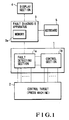
- reference numeral 1 denotes a sequence controller; 2, a large press machine as a control target to be controlled by the sequence controller 1; 1a, a fault detecting section, of the sequence controller 1, for detecting an abnormal state (fault) of the press machine 2; 1b, a control section, of the sequence controller 1, for controlling an operation of the press machine 2 and roughly detecting a fault; 3, a fault diagnosis apparatus, constituted by a memory 3a, a CPU, and the like, for checking the cause of a fault on the basis of a fault detection signal from the sequence controller 1; 4, a display section, constituted by a CRT or the like and connected to the fault diagnosing apparatus 3, for displaying questions, answers, probabilities, and the like in accordance with the interaction between an operator and the apparatus 3; and 5, a keyboard for inputting an answer selected by the operator with respect to the apparatus 3.
- a fault diagnosis apparatus constituted by a memory 3a, a CPU, and the like, for checking the cause of a fault on the basis of a fault detection signal from
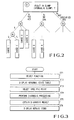
- Fig. 2 shows various data including a fault tree and the like registered in the memory 3a.
- a first question Q1 is set in relation to one fault.
- Three answers A1, A2, and A3 are prepared as choices with respect to the question Q1.
- Questions Q2, Q3, and Q4 are respectively set after the choices. These questions then branch out into choices.
- Final choices reach a cause 1, a cause 2, cause 3,....
- the memory 3a serves to store data representing the number of times the states of the answers A1, A2, and A3 as the choices constituting the fault tree occur, and data representing the number of times the respective answers are used (selected) in the past.
- step ST1 When a fault occurs in the press machine 2, the operator operates the keyboard 5 in step ST1 to select an abnormal state monitor function of the fault diagnosing apparatus. With this operation, a schematic representation of the press machine 2 shown in Fig. 4 is displayed on the display section 4. In this case, the display section 4 displays the occurrence of an abnormal state in a die clamper by changing the display color of hatched portions in Fig. 4.
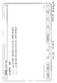
- step ST2 an abnormal state table shown in Fig. 5 is displayed.
- step ST4 When a specific point is designated from this table in step ST3, the flow advances to step ST4 to perform diagnosis processing in which selection of questions and answers is performed in an interactive mode in accordance with the above-mentioned fault tree. With this operation, a diagnosis result, i.e., the cause of the fault can be detected in step ST5.
- step ST5 a message shown in Fig. 7 is displayed, and a manual key is designated as one of function keys.
- An operator in charge of repair can perform a repair operation by referring to the above-mentioned repair items.
- Fig. 10 is a flow chart showing the diagnosis processing in step ST4 in more detail.
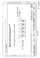
- step ST41 it is determined in step ST41 whether diagnosis processing is performed with respect to a specific abnormal state. If the keyboard 5 is operated to perform this processing, the display section 4 displays the first question Q1 (shown in Fig. 2) with respect to the designated point and the probabilities (frequencies) that the states of the answers (choices) A1, A2, and A3 for the question Q1 occur. These probabilities can be arbitrarily set and changed and can be displayed in an arbitrary order instead of displaying them in the order of decreasing values as in Fig. 6.
- step ST43 If the operator selects the answer A1 in step ST43, stack processing is performed in step ST44 to store the selected question Q1 and answer A1. Thereafter, it is checked in step ST45 whether the answer A1 is a final answer. If NO in step ST45, the flow returns to step ST42 to display the next question Q2 and its answers and waits for selection of an answer in step ST43. The above operation is repeated until the flow reaches to a final answer, and a selected question and answer are stored for each operation.
- a learning key is displayed on the display section 4 as one of function keys in step ST46. If this learning key is depressed once in step ST47, the counts of all the selected answers are updated in the memory 3a in step ST49 through step ST48. Note that if the learning key is consecutively depressed twice, the flow advances to step ST51 to perform error processing. Subsequently, in step ST50, the probabilities of the associated answers are calculated by using the counts updated in step ST49, and the memory 3a is updated on the basis of the calculation result.
- a learning function is added to the fault diagnosis function. That is, the accuracy of probabilities respectively displayed with respect to a plurality of answers for one question is increased every time diagnosis is performed to facilitate selection by an operator. Therefore, the cause of a fault can be detected within a short period of time.
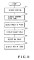
- Fig. 11 is a flow chart showing another method of detecting the cause of a fault and fault repair items. Processing in steps ST1 to ST3 is executed in the same manner as described with reference to Fig. 3.
- a specific point is selected in step ST3
- a plurality of causes associated with the point are displayed together with their probabilities.
- Fig. 2 shows a case wherein the causes 1, 2, 3, ... associated with the question Q1 with respect to the specific point are displayed in the order of decreasing probabilities, as shown in Fig. 9.
- the fault repair items shown in Fig. 8 are displayed in step ST6.
- the present invention when selection of questions and answers is performed in the interactive mode by using a fault tree, one cause of a fault is obtained, and fault repair items are displayed.
- the cause of a fault can be detected within a short period of time.
- repair items for the fault can be detected. Therefore, the above-mentioned MTTR can be increased.
Landscapes
- Engineering & Computer Science (AREA)
- General Engineering & Computer Science (AREA)
- General Physics & Mathematics (AREA)
- Theoretical Computer Science (AREA)
- Physics & Mathematics (AREA)
- Quality & Reliability (AREA)
- Computer Hardware Design (AREA)
- Automation & Control Theory (AREA)
- Testing And Monitoring For Control Systems (AREA)
- Testing Or Calibration Of Command Recording Devices (AREA)
- Testing Of Devices, Machine Parts, Or Other Structures Thereof (AREA)
- Test And Diagnosis Of Digital Computers (AREA)
- Programmable Controllers (AREA)
Applications Claiming Priority (2)
| Application Number | Priority Date | Filing Date | Title |
|---|---|---|---|
| JP294743/89 | 1989-11-13 | ||
| JP1294743A JPH03154846A (ja) | 1989-11-13 | 1989-11-13 | 故障診断装置 |
Publications (2)
| Publication Number | Publication Date |
|---|---|
| EP0428134A2 true EP0428134A2 (de) | 1991-05-22 |
| EP0428134A3 EP0428134A3 (en) | 1993-02-24 |
Family
ID=17811735
Family Applications (1)
| Application Number | Title | Priority Date | Filing Date |
|---|---|---|---|
| EP19900121714 Withdrawn EP0428134A3 (en) | 1989-11-13 | 1990-11-13 | Fault diagnosing apparatus and method |
Country Status (2)
| Country | Link |
|---|---|
| EP (1) | EP0428134A3 (de) |
| JP (1) | JPH03154846A (de) |
Cited By (4)
| Publication number | Priority date | Publication date | Assignee | Title |
|---|---|---|---|---|
| WO2006043993A1 (en) * | 2004-10-14 | 2006-04-27 | Snap-On Incorporated | Prioritized test procedure and step display using statistical feedback |
| WO2013104419A1 (de) * | 2012-01-11 | 2013-07-18 | Siemens Aktiengesellschaft | Unterstützung der störfallprävention einer industrieanlage mit hilfe eines fehlermodells |
| CN109857049A (zh) * | 2017-11-30 | 2019-06-07 | 上海梅山钢铁股份有限公司 | 高炉阀门plc逻辑指令控制故障原因判断方法 |
| FR3164803A1 (fr) * | 2024-07-18 | 2026-01-23 | Fives CortX | Procede de diagnostic automatise d’une machine de production |
Families Citing this family (8)
| Publication number | Priority date | Publication date | Assignee | Title |
|---|---|---|---|---|
| JP3231536B2 (ja) * | 1993-02-25 | 2001-11-26 | トヨタ自動車株式会社 | プレス機械の異常診断方法 |
| JP3573559B2 (ja) * | 1996-03-04 | 2004-10-06 | 株式会社日立製作所 | 保守支援システム |
| JP2000210800A (ja) | 1999-01-27 | 2000-08-02 | Komatsu Ltd | 産業機械のモニタ方法およびその装置 |
| JP2000353094A (ja) * | 1999-06-10 | 2000-12-19 | Ishikawajima Harima Heavy Ind Co Ltd | 機器の故障診断装置及び方法 |
| JP2001202125A (ja) * | 2000-01-20 | 2001-07-27 | Snap On Tools Corp | 装置作動状態のダイナミック診断システム |
| JP4706890B2 (ja) * | 2001-05-08 | 2011-06-22 | マツダ株式会社 | 車載の遠隔故障診断装置 |
| JP2004227175A (ja) * | 2003-01-21 | 2004-08-12 | Sony Corp | メンテナンスシステム |
| CN102393666B (zh) * | 2011-09-21 | 2013-05-01 | 哈尔滨工业大学 | 一种探测器嵌入式自主故障监测与异常数据记录装置 |
Family Cites Families (3)
| Publication number | Priority date | Publication date | Assignee | Title |
|---|---|---|---|---|
| US4571679A (en) * | 1983-09-06 | 1986-02-18 | The United States Of America As Represented By The Secretary Of The Navy | Fault tree data array |
| JPS63284641A (ja) * | 1987-05-18 | 1988-11-21 | Mitsubishi Electric Corp | エキスパ−ト故障診断システム |
| JPS6481008A (en) * | 1987-09-22 | 1989-03-27 | Fanuc Ltd | Expert system for machine tool containing nc device |
-
1989
- 1989-11-13 JP JP1294743A patent/JPH03154846A/ja active Pending
-
1990
- 1990-11-13 EP EP19900121714 patent/EP0428134A3/en not_active Withdrawn
Cited By (6)
| Publication number | Priority date | Publication date | Assignee | Title |
|---|---|---|---|---|
| WO2006043993A1 (en) * | 2004-10-14 | 2006-04-27 | Snap-On Incorporated | Prioritized test procedure and step display using statistical feedback |
| US7142960B2 (en) | 2004-10-14 | 2006-11-28 | Snap-On Incorporated | Prioritized test procedure and step display using statistical feedback |
| WO2013104419A1 (de) * | 2012-01-11 | 2013-07-18 | Siemens Aktiengesellschaft | Unterstützung der störfallprävention einer industrieanlage mit hilfe eines fehlermodells |
| CN109857049A (zh) * | 2017-11-30 | 2019-06-07 | 上海梅山钢铁股份有限公司 | 高炉阀门plc逻辑指令控制故障原因判断方法 |
| CN109857049B (zh) * | 2017-11-30 | 2022-02-22 | 上海梅山钢铁股份有限公司 | 高炉阀门plc逻辑指令控制故障原因判断方法 |
| FR3164803A1 (fr) * | 2024-07-18 | 2026-01-23 | Fives CortX | Procede de diagnostic automatise d’une machine de production |
Also Published As
| Publication number | Publication date |
|---|---|
| JPH03154846A (ja) | 1991-07-02 |
| EP0428134A3 (en) | 1993-02-24 |
Similar Documents
| Publication | Publication Date | Title |
|---|---|---|
| EP0428135A2 (de) | Gerät und Verfahren zur Fehlerdiagnose | |
| EP0424869A1 (de) | Vorrichtung zur Fehlerprädiktion | |
| EP0428134A2 (de) | Fehlerdiagnosegerät und Verfahren | |
| US5321829A (en) | Graphical interfaces for monitoring ladder logic programs | |
| US4991076A (en) | Method and apparatus for creating custom displays for monitoring ladder logic programs | |
| US5997167A (en) | Programmable controller including diagnostic and simulation facilities | |
| US3975622A (en) | Programmable logic controller system | |
| KR100376901B1 (ko) | 플랜트감시장치및감시방법 | |
| US4736340A (en) | Processor generating control programs for a programmable controller | |
| US5276811A (en) | Method for emulating programmable logic controller by exchanging information between debug program which emulates I/O devices and ladder logic program | |
| GB2298725A (en) | Processing quality control data | |
| JPH06507991A (ja) | 知識ベースの形成及びそのシミュレーション | |
| EP0292914B1 (de) | Fehlerdiagnosegerät für gesteuerte Einrichtung | |
| JPS6365966B2 (de) | ||
| JP3098199B2 (ja) | 燃焼機器修理支援装置及び故障データ収集・利用方法 | |
| JPH10143232A (ja) | 数値制御工作機械の機械管理システム | |
| EP0441547B1 (de) | Simulation von menschlicher Ausübung eines Prozessdurchführungsverfahrens | |
| JP3165927B2 (ja) | プラント監視制御装置 | |
| JPS63284641A (ja) | エキスパ−ト故障診断システム | |
| US5315500A (en) | Diagnostic system and method for detecting retardation of an object controlled by a programmable controller | |
| JPH06274298A (ja) | 制御機器の監視装置 | |
| JPH086484A (ja) | プラント運転訓練シミュレータ及びその訓練内容設定方法 | |
| EP0136485A2 (de) | Überwachungsverfahren für einen Prozess und Gerät für eine programmierbare Steuerung | |
| JPH0679245B2 (ja) | プログラマブルコントロ−ラのシ−ケンスプログラム実行方式 | |
| JPH04320925A (ja) | プロセス状態表示装置 |
Legal Events
| Date | Code | Title | Description |
|---|---|---|---|
| PUAI | Public reference made under article 153(3) epc to a published international application that has entered the european phase |
Free format text: ORIGINAL CODE: 0009012 |
|
| 17P | Request for examination filed |
Effective date: 19901129 |
|
| AK | Designated contracting states |
Kind code of ref document: A2 Designated state(s): DE GB |
|
| PUAL | Search report despatched |
Free format text: ORIGINAL CODE: 0009013 |
|
| AK | Designated contracting states |
Kind code of ref document: A3 Designated state(s): DE GB |
|
| STAA | Information on the status of an ep patent application or granted ep patent |
Free format text: STATUS: THE APPLICATION HAS BEEN WITHDRAWN |
|
| 18W | Application withdrawn |
Withdrawal date: 19930528 |