EP0428135A2 - Appareil et méthode de diagnostic de fautes - Google Patents
Appareil et méthode de diagnostic de fautes Download PDFInfo
- Publication number
- EP0428135A2 EP0428135A2 EP90121715A EP90121715A EP0428135A2 EP 0428135 A2 EP0428135 A2 EP 0428135A2 EP 90121715 A EP90121715 A EP 90121715A EP 90121715 A EP90121715 A EP 90121715A EP 0428135 A2 EP0428135 A2 EP 0428135A2
- Authority
- EP
- European Patent Office
- Prior art keywords
- fault
- choices
- repair items
- section
- question
- Prior art date
- Legal status (The legal status is an assumption and is not a legal conclusion. Google has not performed a legal analysis and makes no representation as to the accuracy of the status listed.)
- Withdrawn
Links
Images





Classifications
-
- G—PHYSICS
- G06—COMPUTING OR CALCULATING; COUNTING
- G06F—ELECTRIC DIGITAL DATA PROCESSING
- G06F11/00—Error detection; Error correction; Monitoring
- G06F11/22—Detection or location of defective computer hardware by testing during standby operation or during idle time, e.g. start-up testing
- G06F11/2257—Detection or location of defective computer hardware by testing during standby operation or during idle time, e.g. start-up testing using expert systems
-
- G—PHYSICS
- G05—CONTROLLING; REGULATING
- G05B—CONTROL OR REGULATING SYSTEMS IN GENERAL; FUNCTIONAL ELEMENTS OF SUCH SYSTEMS; MONITORING OR TESTING ARRANGEMENTS FOR SUCH SYSTEMS OR ELEMENTS
- G05B19/00—Program-control systems
- G05B19/02—Program-control systems electric
- G05B19/04—Program control other than numerical control, i.e. in sequence controllers or logic controllers
- G05B19/042—Program control other than numerical control, i.e. in sequence controllers or logic controllers using digital processors
- G05B19/0428—Safety, monitoring
-
- G—PHYSICS
- G05—CONTROLLING; REGULATING
- G05B—CONTROL OR REGULATING SYSTEMS IN GENERAL; FUNCTIONAL ELEMENTS OF SUCH SYSTEMS; MONITORING OR TESTING ARRANGEMENTS FOR SUCH SYSTEMS OR ELEMENTS
- G05B2219/00—Program-control systems
- G05B2219/20—Pc systems
- G05B2219/23—Pc programming
- G05B2219/23157—Display process, synoptic, legend, pictogram, mimic
-
- G—PHYSICS
- G05—CONTROLLING; REGULATING
- G05B—CONTROL OR REGULATING SYSTEMS IN GENERAL; FUNCTIONAL ELEMENTS OF SUCH SYSTEMS; MONITORING OR TESTING ARRANGEMENTS FOR SUCH SYSTEMS OR ELEMENTS
- G05B2219/00—Program-control systems
- G05B2219/20—Pc systems
- G05B2219/24—Pc safety
- G05B2219/24018—Computer assisted repair, diagnostic
-
- G—PHYSICS
- G05—CONTROLLING; REGULATING
- G05B—CONTROL OR REGULATING SYSTEMS IN GENERAL; FUNCTIONAL ELEMENTS OF SUCH SYSTEMS; MONITORING OR TESTING ARRANGEMENTS FOR SUCH SYSTEMS OR ELEMENTS
- G05B2219/00—Program-control systems
- G05B2219/20—Pc systems
- G05B2219/24—Pc safety
- G05B2219/24053—Diagnostic of controlled machine
-
- G—PHYSICS
- G05—CONTROLLING; REGULATING
- G05B—CONTROL OR REGULATING SYSTEMS IN GENERAL; FUNCTIONAL ELEMENTS OF SUCH SYSTEMS; MONITORING OR TESTING ARRANGEMENTS FOR SUCH SYSTEMS OR ELEMENTS
- G05B2219/00—Program-control systems
- G05B2219/20—Pc systems
- G05B2219/24—Pc safety
- G05B2219/24085—Analyze, trace fault signals according to tree, table
-
- G—PHYSICS
- G05—CONTROLLING; REGULATING
- G05B—CONTROL OR REGULATING SYSTEMS IN GENERAL; FUNCTIONAL ELEMENTS OF SUCH SYSTEMS; MONITORING OR TESTING ARRANGEMENTS FOR SUCH SYSTEMS OR ELEMENTS
- G05B2219/00—Program-control systems
- G05B2219/20—Pc systems
- G05B2219/24—Pc safety
- G05B2219/24086—Expert system, guidance operator, locate fault and indicate how to repair
-
- G—PHYSICS
- G05—CONTROLLING; REGULATING
- G05B—CONTROL OR REGULATING SYSTEMS IN GENERAL; FUNCTIONAL ELEMENTS OF SUCH SYSTEMS; MONITORING OR TESTING ARRANGEMENTS FOR SUCH SYSTEMS OR ELEMENTS
- G05B2219/00—Program-control systems
- G05B2219/20—Pc systems
- G05B2219/24—Pc safety
- G05B2219/24087—After correct repair, update fault tree
-
- G—PHYSICS
- G05—CONTROLLING; REGULATING
- G05B—CONTROL OR REGULATING SYSTEMS IN GENERAL; FUNCTIONAL ELEMENTS OF SUCH SYSTEMS; MONITORING OR TESTING ARRANGEMENTS FOR SUCH SYSTEMS OR ELEMENTS
- G05B2219/00—Program-control systems
- G05B2219/20—Pc systems
- G05B2219/24—Pc safety
- G05B2219/24093—Display, show place of error, fault
Definitions
- the present invention relates to a fault diagnosing apparatus for detecting the cause of a fault when a control target in, e.g., a sequence control system failed, and a corresponding diagnosing method.
- a control target such as a plant, a processing apparatus, or an equipment system
- a control target is properly operated by controlling a large number of sensors and actuators, e.g., limit switches and solenoid valves, at predetermined timings based on a sequence program using a sequence controller in accordance with signals from various sensors arranged at the respective portions of the control target.
- sensors and actuators e.g., limit switches and solenoid valves
- a system has a function of diagnosing a fault in a control target during an operation. When a fault is detected, the fault is displayed by means of a lamp, a message, or the like.
- faults are very roughly diagnosed, and the number of items of faults which can be detected is very small.
- the number of items is about 10 to 250.
- fault diagnosis of the above-mentioned sequence controller itself including a large number of contacts and actuators, various sensors, and the like, is performed.
- the display contents of abnormal states are limited to only phenomena, and true causes thereof are not displayed at all.
- sequence program includes a control program and a program for fault diagnosis.
- the two programs are alternately executed. Therefore, the total capacity of programs is increased to increase a programming load. This may also interfere with the execution of the control program, and pose other problems, e.g., that fault diagnosis cannot be performed. at high speed.
- an operator in charge of maintenance checks a portion at which the fault has occurred, and also checks an operation manual. The operator then determines the cause of the fault or the repair items and performs a proper operation.
- MTTR total time to repair faults/total number of faults to be repaired
- the present invention has been made to solve the above problem, and has as its object to provide a fault diagnosing apparatus which can detect the cause of a fault-within a short period of time and can inform an operator of repair items indicating a repair method.
- a fault diagnosing apparatus comprising a fault tree in which a plurality of choices are set with respect to one question associated with a cause of a fault of a fault diagnosis target, answers and choices branch off from each of the choices, and final choices reach causes of the fault, storage means for storing fault repair items with respect to the causes of the fault, read control means for, in response to an input operation to select one of the choices, reading out the selected choice, a corresponding question, choices branching off therefrom, and fault repair items, display means for displaying the question, the choices, and the fault repair items which are read out by the read control means, designating means for designating to update the fault repair items, and rewrite means for rewriting some of the fault repair items stored in the storage means by using update data externally provided on the basis of the designation from the designating means.
- repair items of the fault are displayed.
- the repair items are designated to be selectively updated, rewriting of the repair items is performed in accordance with the designation.
- reference numeral 1 denotes a sequence controller; 2, a large press machine as a control target to be controlled by the sequence controller 1; 1a, a fault detecting section, of the sequence controller 1, for detecting an abnormal state (fault) of the press machine 2; 1b, a control section, of the sequence controller 1, for controlling an operation of the press machine 2 and roughly detecting a fault; 3, a fault diagnosis apparatus, constituted by a memory 3a, a CPU, and the like, for checking the cause of a fault on the basis of a fault detection signal from the sequence controller 1; 4, a display section, constituted by a CRT or the like and connected to the fault diagnosing apparatus 3, for displaying questions, answers, probabilities, and the like in accordance with the interaction between an operator and the apparatus 3; 5, a keyboard for inputting an answer selected by the operator with respect to the apparatus 3; and 6, a floppy disk (FD) unit for providing update data of repair items to the fault diagnosing apparatus 3.
- FD floppy disk
- Fig. 2 shows various data including a fault tree and the like registered in the memory 3a.
- a first question Q1 is set in relation to one fault.
- Three answers A1, A2, and A3 are prepared as choices with respect to the question Q1.
- Questions Q2, Q3, and Q4 are respectively set after the choices. These questions then branch out into choices.
- Final choices reach a cause 1, a cause 2, cause 3,....
- the memory 3a serves to store data representing the number of times the states of the answers A1, A2, and A3 as the choices constituting the fault tree occur, and data representing the number of times the respective answers are used (selected) in the past.
- the memory 3a stores fault repair items with respect to the causes 1, 2, 3....
- step ST1 When a fault occurs in the press machine 2, the operator operates the keyboard 5 in step ST1 to select an abnormal state monitor function of the fault diagnosing apparatus. With this operation, a schematic representation of the press machine 2 shown in Fig. 4 is displayed on the display section 4. In this case, the display section 4 displays the occurrence of an abnormal state in a die clamper by changing the display color of hatched portions in Fig. 4.
- step ST2 an abnormal state table shown in Fig. 5 is displayed.
- step ST4 When a specific point is designated from this table in step ST3, the flow advances to step ST4 to perform diagnosis processing in which selection of questions and answers is performed in an interactive mode in accordance with the above-mentioned fault tree.
- a diagnosis result i.e., the cause of the fault can be detected in step STS.
- step STS a message shown in Fig. 7 is displayed, and a manual key is designated as one of function keys.
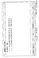
- repair items with respect to the cause of a fault are displayed, as shown in Fig. 8. These items are displayed in the order of decreasing probabilities, as shown in Fig. 9.
- An operator in charge of repair can perform a repair operation by referring to the above-mentioned repair items.
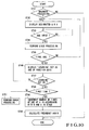
- Fig. 10 is a flow chart showing the diagnosis processing in step ST4 in more detail.
- step ST41 it is determined in step ST41 whether diagnosis processing is performed with respect to a specific abnormal state. If the keyboard 5 is operated to perform this processing, the display section 4 displays the first question Q1 (shown in Fig. 2) with respect to the designated point and the probabilities (frequencies) that the states of the answers (choices) A1, A2, and A3 for the question Q1 occur. These probabilities can be arbitrarily set and changed and can be displayed in an arbitrary order instead of displaying them in the order of decreasing values as in Fig. 6.
- step ST43 If the operator selects the answer A1 in step ST43, stack processing is performed in step ST44 to store the selected question Q1 and answer A1. Thereafter, it is checked in step ST45 whether the answer A1 is a final answer. If NO in step ST4S, the flow returns to step ST42 to display the next question Q2 and its answers and waits for selection of an answer in step ST43. The above operation is repeated until the flow reaches to a final answer, and a selected question and answer are stored for each operation.
- a learning key is displayed on the display section 4 as one of function keys in step ST46. If this learning key is depressed once in step ST47, the counts of all the selected answers are updated in the memory 3a in step ST49 through step ST48. Note that if the learning key is consecutively depressed twice, the flow advances to step ST51 to perform error processing. Subsequently, in step ST50, the probabilities of the associated answers are calculated by using the counts updated in step ST49, and the memory 3a is updated on the basis of the calculation result.
- a learning function is added to the fault diagnosis function. That is, the accuracy of probabilities respectively displayed with respect to a plurality of answers for one question is increased every time diagnosis is performed to facilitate selection by an operator. Therefore, the cause of a fault can be detected within a short period of time.
- Fig. 11 is a flow chart showing an operation to be executed by a CPU 3b when fault repair items stored in the memory 3a are to be updated.
- the memory 3a stores fault trees for a plurality of faults.
- the memory 3a normally stores a plurality of causes of faults for the respective fault trees, and also stores fault repair items for the respective causes of faults. Therefore, the memory 3a stores data of a large number of fault repair items. When these fault repair items are to be updated, corresponding portions of the memory 3a must be rewritten.
- the FD unit 6 is used as an input unit for inputting update data for this update operation.
- step ST1 when a fault repair item revision key as one of the function keys is depressed in step ST1, an "input range" is displayed in a lower portion of the screen of the display section 4 in step ST2.
- step ST3 an address range (e.g., 10 to 20) corresponding to portions of the contents of the memory 3a which are to be updated.
- step ST6 update data reproduced from the FD of the FD unit 6 are sequentially compared with the data read out from the memory 3a one by one.
- the present invention when selection of questions and answers is performed in the interactive mode by using a fault tree, one cause of a fault is obtained, and fault repair items are displayed. In addition, updated fault repair items can be displayed. With this arrangement, the cause of a fault can be detected within a short period of time. In addition, repair items for the fault can be detected. Therefore, various effects, e.g., an increase in the above-mentioned MTTR, and satisfactory response to an update of the fault repair items, can be obtained.
Landscapes
- Engineering & Computer Science (AREA)
- General Physics & Mathematics (AREA)
- Theoretical Computer Science (AREA)
- General Engineering & Computer Science (AREA)
- Physics & Mathematics (AREA)
- Quality & Reliability (AREA)
- Computer Hardware Design (AREA)
- Automation & Control Theory (AREA)
- Test And Diagnosis Of Digital Computers (AREA)
- Programmable Controllers (AREA)
- Testing Or Calibration Of Command Recording Devices (AREA)
- Testing Of Devices, Machine Parts, Or Other Structures Thereof (AREA)
- Testing And Monitoring For Control Systems (AREA)
Applications Claiming Priority (2)
| Application Number | Priority Date | Filing Date | Title |
|---|---|---|---|
| JP294744/89 | 1989-11-13 | ||
| JP1294744A JPH03154847A (ja) | 1989-11-13 | 1989-11-13 | 故障診断装置 |
Publications (2)
| Publication Number | Publication Date |
|---|---|
| EP0428135A2 true EP0428135A2 (fr) | 1991-05-22 |
| EP0428135A3 EP0428135A3 (en) | 1993-02-24 |
Family
ID=17811746
Family Applications (1)
| Application Number | Title | Priority Date | Filing Date |
|---|---|---|---|
| EP19900121715 Withdrawn EP0428135A3 (en) | 1989-11-13 | 1990-11-13 | Fault diagnosing apparatus and method |
Country Status (2)
| Country | Link |
|---|---|
| EP (1) | EP0428135A3 (fr) |
| JP (1) | JPH03154847A (fr) |
Cited By (24)
| Publication number | Priority date | Publication date | Assignee | Title |
|---|---|---|---|---|
| EP0548777A1 (fr) * | 1991-12-20 | 1993-06-30 | G.D Societa' Per Azioni | Système d'identification des malfonctions sur un site de production et d'emballage |
| EP0562901A1 (fr) * | 1992-03-27 | 1993-09-29 | AEROSPATIALE Société Nationale Industrielle | Dispositif d'aide à la maintenance pour torche à plasma |
| WO1996020439A1 (fr) * | 1994-12-27 | 1996-07-04 | Siemens Aktiengesellschaft | Systeme assiste par ordinateur pour detecter l'incident a l'origine d'une panne dans une installation technique |
| US5596712A (en) * | 1991-07-08 | 1997-01-21 | Hitachi, Ltd. | Method and system for diagnosis and analysis of products troubles |
| WO2002017026A3 (fr) * | 2000-08-22 | 2002-06-06 | Siemens Ag | Systeme et procede pour l'etablissement de rapports lie au contexte, en particulier dans le domaine de la production, du montage, du service ou de la maintenance |
| EP1243989A1 (fr) * | 2001-03-23 | 2002-09-25 | Siemens Aktiengesellschaft | Procédé pour réduire les efforts de programmation dans une commande programmable avec une unité centrale et un dispositif d'entrée de commande |
| EP1243988A1 (fr) * | 2001-03-23 | 2002-09-25 | Siemens Aktiengesellschaft | Procédé pour réduire les efforts de programmation dans une commande programmable avec une unité centrale et un dispositif d'entré de commandes |
| WO2005031486A1 (fr) * | 2003-09-26 | 2005-04-07 | Siemens Aktiengesellschaft | Procede et dispositif pour la determination des causes de defaillances et de limitations de rendement dans des installations |
| WO2006068658A3 (fr) * | 2004-11-02 | 2006-08-10 | Snap On Tools Corp | Procede et systeme permettant d'ameliorer les aides au diagnostic de machines par retroaction statistique |
| DE10019792B4 (de) * | 1999-04-20 | 2006-09-14 | Nec Corp. | Schaltungsanordnung und Verfahren zur Erfassung von Fehlerdaten |
| WO2007024273A1 (fr) * | 2005-08-24 | 2007-03-01 | Snap-On Incorporated | Procede permettant de modifier de façon adaptative des informations de diagnostic de vehicule |
| EP1394759A3 (fr) * | 2002-08-23 | 2007-06-27 | Link Systemtechnik GmbH | Analyse des défaillances et/ou d'état |
| EP1898286A1 (fr) * | 2006-08-29 | 2008-03-12 | Yamazaki Mazak Corporation | Système de support destiné à la prédiction de défaillances, à l'avertissement et à la restauration du fonctionnement d'une machine |
| US7349746B2 (en) | 2004-09-10 | 2008-03-25 | Exxonmobil Research And Engineering Company | System and method for abnormal event detection in the operation of continuous industrial processes |
| US7424395B2 (en) | 2004-09-10 | 2008-09-09 | Exxonmobil Research And Engineering Company | Application of abnormal event detection technology to olefins recovery trains |
| US7567887B2 (en) * | 2004-09-10 | 2009-07-28 | Exxonmobil Research And Engineering Company | Application of abnormal event detection technology to fluidized catalytic cracking unit |
| US7720641B2 (en) | 2006-04-21 | 2010-05-18 | Exxonmobil Research And Engineering Company | Application of abnormal event detection technology to delayed coking unit |
| US7761172B2 (en) | 2006-03-21 | 2010-07-20 | Exxonmobil Research And Engineering Company | Application of abnormal event detection (AED) technology to polymers |
| US8001476B2 (en) | 2004-11-16 | 2011-08-16 | Open Text Inc. | Cellular user interface |
| US8005645B2 (en) | 2004-09-10 | 2011-08-23 | Exxonmobil Research And Engineering Company | Application of abnormal event detection technology to hydrocracking units |
| US8793604B2 (en) | 2004-11-16 | 2014-07-29 | Open Text S.A. | Spatially driven content presentation in a cellular environment |
| US8862250B2 (en) | 2010-05-07 | 2014-10-14 | Exxonmobil Research And Engineering Company | Integrated expert system for identifying abnormal events in an industrial plant |
| IT201900007581A1 (it) * | 2019-05-30 | 2020-11-30 | Gd Spa | Procedimento per il ripristino dello stato funzionale di una macchina automatica per la produzione o l’impacchettamento di prodotti di consumo |
| CN113994325A (zh) * | 2019-06-19 | 2022-01-28 | 住友重机械工业株式会社 | 支援装置、显示装置、支援方法及支援程序 |
Families Citing this family (9)
| Publication number | Priority date | Publication date | Assignee | Title |
|---|---|---|---|---|
| JPH05133224A (ja) * | 1991-04-19 | 1993-05-28 | Yamaha Motor Co Ltd | エンジンの排気管 |
| JP2692431B2 (ja) * | 1991-07-10 | 1997-12-17 | 日本電気株式会社 | 画像選択装置 |
| JP3019227B2 (ja) * | 1991-10-17 | 2000-03-13 | 株式会社戸上電機製作所 | 送配電線事故診断方法 |
| JP3231536B2 (ja) * | 1993-02-25 | 2001-11-26 | トヨタ自動車株式会社 | プレス機械の異常診断方法 |
| JP3151093B2 (ja) * | 1993-10-19 | 2001-04-03 | 株式会社日立製作所 | 故障診断方法 |
| JP3573559B2 (ja) * | 1996-03-04 | 2004-10-06 | 株式会社日立製作所 | 保守支援システム |
| JP2000210800A (ja) | 1999-01-27 | 2000-08-02 | Komatsu Ltd | 産業機械のモニタ方法およびその装置 |
| JP4422180B2 (ja) | 2007-12-13 | 2010-02-24 | ファナック株式会社 | 水位異常検出機能を備えたワイヤカット放電加工機およびその水位異常アラーム発生原因特定方法 |
| CN107239668B (zh) * | 2017-06-13 | 2020-09-01 | 重庆大学 | 一种基于断点模型的数控磨床液压系统故障树分析方法 |
Family Cites Families (3)
| Publication number | Priority date | Publication date | Assignee | Title |
|---|---|---|---|---|
| US4571679A (en) * | 1983-09-06 | 1986-02-18 | The United States Of America As Represented By The Secretary Of The Navy | Fault tree data array |
| US4847795A (en) * | 1987-08-24 | 1989-07-11 | Hughes Aircraft Company | System for diagnosing defects in electronic assemblies |
| JPS6481008A (en) * | 1987-09-22 | 1989-03-27 | Fanuc Ltd | Expert system for machine tool containing nc device |
-
1989
- 1989-11-13 JP JP1294744A patent/JPH03154847A/ja active Pending
-
1990
- 1990-11-13 EP EP19900121715 patent/EP0428135A3/en not_active Withdrawn
Cited By (36)
| Publication number | Priority date | Publication date | Assignee | Title |
|---|---|---|---|---|
| US5596712A (en) * | 1991-07-08 | 1997-01-21 | Hitachi, Ltd. | Method and system for diagnosis and analysis of products troubles |
| EP0548777A1 (fr) * | 1991-12-20 | 1993-06-30 | G.D Societa' Per Azioni | Système d'identification des malfonctions sur un site de production et d'emballage |
| EP0562901A1 (fr) * | 1992-03-27 | 1993-09-29 | AEROSPATIALE Société Nationale Industrielle | Dispositif d'aide à la maintenance pour torche à plasma |
| FR2689359A1 (fr) * | 1992-03-27 | 1993-10-01 | Aerospatiale | Dispositif d'aide à la maintenance pour torche à plasma. |
| US5446255A (en) * | 1992-03-27 | 1995-08-29 | Societe Anonyme Dite: Aerospatiale Societe Nationale Industrielle | Expert system for plasma torch |
| WO1996020439A1 (fr) * | 1994-12-27 | 1996-07-04 | Siemens Aktiengesellschaft | Systeme assiste par ordinateur pour detecter l'incident a l'origine d'une panne dans une installation technique |
| DE10019792B4 (de) * | 1999-04-20 | 2006-09-14 | Nec Corp. | Schaltungsanordnung und Verfahren zur Erfassung von Fehlerdaten |
| WO2002017026A3 (fr) * | 2000-08-22 | 2002-06-06 | Siemens Ag | Systeme et procede pour l'etablissement de rapports lie au contexte, en particulier dans le domaine de la production, du montage, du service ou de la maintenance |
| EP1243989A1 (fr) * | 2001-03-23 | 2002-09-25 | Siemens Aktiengesellschaft | Procédé pour réduire les efforts de programmation dans une commande programmable avec une unité centrale et un dispositif d'entrée de commande |
| EP1243988A1 (fr) * | 2001-03-23 | 2002-09-25 | Siemens Aktiengesellschaft | Procédé pour réduire les efforts de programmation dans une commande programmable avec une unité centrale et un dispositif d'entré de commandes |
| EP1394759A3 (fr) * | 2002-08-23 | 2007-06-27 | Link Systemtechnik GmbH | Analyse des défaillances et/ou d'état |
| WO2005031486A1 (fr) * | 2003-09-26 | 2005-04-07 | Siemens Aktiengesellschaft | Procede et dispositif pour la determination des causes de defaillances et de limitations de rendement dans des installations |
| US8005645B2 (en) | 2004-09-10 | 2011-08-23 | Exxonmobil Research And Engineering Company | Application of abnormal event detection technology to hydrocracking units |
| NO338660B1 (no) * | 2004-09-10 | 2016-09-26 | Exxonmobil Res And Engineering Co | System og fremgangsmåte for detektering av unormale hendelser under drift av kontinuerlige industrielle prosesser |
| US7349746B2 (en) | 2004-09-10 | 2008-03-25 | Exxonmobil Research And Engineering Company | System and method for abnormal event detection in the operation of continuous industrial processes |
| US7424395B2 (en) | 2004-09-10 | 2008-09-09 | Exxonmobil Research And Engineering Company | Application of abnormal event detection technology to olefins recovery trains |
| US7567887B2 (en) * | 2004-09-10 | 2009-07-28 | Exxonmobil Research And Engineering Company | Application of abnormal event detection technology to fluidized catalytic cracking unit |
| WO2006068658A3 (fr) * | 2004-11-02 | 2006-08-10 | Snap On Tools Corp | Procede et systeme permettant d'ameliorer les aides au diagnostic de machines par retroaction statistique |
| US10055428B2 (en) | 2004-11-16 | 2018-08-21 | Open Text Sa Ulc | Spatially driven content presentation in a cellular environment |
| US8793604B2 (en) | 2004-11-16 | 2014-07-29 | Open Text S.A. | Spatially driven content presentation in a cellular environment |
| US10222943B2 (en) | 2004-11-16 | 2019-03-05 | Open Text Sa Ulc | Cellular user interface |
| US8001476B2 (en) | 2004-11-16 | 2011-08-16 | Open Text Inc. | Cellular user interface |
| US9304837B2 (en) | 2004-11-16 | 2016-04-05 | Open Text S.A. | Cellular user interface |
| WO2007024273A1 (fr) * | 2005-08-24 | 2007-03-01 | Snap-On Incorporated | Procede permettant de modifier de façon adaptative des informations de diagnostic de vehicule |
| US7706936B2 (en) | 2005-08-24 | 2010-04-27 | Snap-On Incorporated | Method and system for adaptively modifying diagnostic vehicle information |
| US7761172B2 (en) | 2006-03-21 | 2010-07-20 | Exxonmobil Research And Engineering Company | Application of abnormal event detection (AED) technology to polymers |
| US7720641B2 (en) | 2006-04-21 | 2010-05-18 | Exxonmobil Research And Engineering Company | Application of abnormal event detection technology to delayed coking unit |
| EP1898286A1 (fr) * | 2006-08-29 | 2008-03-12 | Yamazaki Mazak Corporation | Système de support destiné à la prédiction de défaillances, à l'avertissement et à la restauration du fonctionnement d'une machine |
| US8862250B2 (en) | 2010-05-07 | 2014-10-14 | Exxonmobil Research And Engineering Company | Integrated expert system for identifying abnormal events in an industrial plant |
| IT201900007581A1 (it) * | 2019-05-30 | 2020-11-30 | Gd Spa | Procedimento per il ripristino dello stato funzionale di una macchina automatica per la produzione o l’impacchettamento di prodotti di consumo |
| WO2020240503A1 (fr) * | 2019-05-30 | 2020-12-03 | G.D Societa' Per Azioni | Procédé de restauration de l'état fonctionnel d'une machine automatique pour la production ou l'emballage de produits de consommation |
| US12130615B2 (en) | 2019-05-30 | 2024-10-29 | G.D Societa' Per Azioni | Method to restore the functional state of an automatic machine for the production or the packaging of consumer products |
| EP4679214A1 (fr) * | 2019-05-30 | 2026-01-14 | G.D Societa' Per Azioni | Procédé pour rétablir l'état fonctionnel d'une machine automatique pour la production ou l'emballage de produits de consommation |
| CN113994325A (zh) * | 2019-06-19 | 2022-01-28 | 住友重机械工业株式会社 | 支援装置、显示装置、支援方法及支援程序 |
| EP3989026A4 (fr) * | 2019-06-19 | 2022-10-05 | Sumitomo Heavy Industries, Ltd. | Dispositif d'aide, dispositif d'affichage, procédé d'aide, et programme d'aide |
| TWI837371B (zh) * | 2019-06-19 | 2024-04-01 | 日商住友重機械工業股份有限公司 | 支援裝置、顯示裝置、支援方法及支援程式 |
Also Published As
| Publication number | Publication date |
|---|---|
| JPH03154847A (ja) | 1991-07-02 |
| EP0428135A3 (en) | 1993-02-24 |
Similar Documents
| Publication | Publication Date | Title |
|---|---|---|
| EP0428135A2 (fr) | Appareil et méthode de diagnostic de fautes | |
| EP0424869A1 (fr) | Appareil pour diagnostiquer des erreurs | |
| US5321829A (en) | Graphical interfaces for monitoring ladder logic programs | |
| US5997167A (en) | Programmable controller including diagnostic and simulation facilities | |
| EP0428134A2 (fr) | Appareil et méthode de diagnostic d'une faute | |
| US5469352A (en) | Operation history display device of numerical control apparatus | |
| US5267145A (en) | Method and apparatus for program navigation and editing for ladder logic programs by determining which instructions reference a selected data element address | |
| KR100376901B1 (ko) | 플랜트감시장치및감시방법 | |
| US5276811A (en) | Method for emulating programmable logic controller by exchanging information between debug program which emulates I/O devices and ladder logic program | |
| JPH06507991A (ja) | 知識ベースの形成及びそのシミュレーション | |
| JP4438331B2 (ja) | 制御テスト支援システム、及び制御テスト支援システム用プログラム | |
| JPS6365966B2 (fr) | ||
| EP0292914B1 (fr) | Appareil de diagnostic de pannes pour dispositifs commandés | |
| JP3098199B2 (ja) | 燃焼機器修理支援装置及び故障データ収集・利用方法 | |
| EP0476139B1 (fr) | Procede de programmation automatique interactif | |
| JPH10143232A (ja) | 数値制御工作機械の機械管理システム | |
| JP3666507B2 (ja) | シミュレーション支援ツールおよびラダープログラムの検証システムならびにテスト入力ラダープログラム生成方法ならびにラダープログラムの検証方法 | |
| JPH10301763A (ja) | ディジタル制御装置のプログラム作成支援装置 | |
| JP3211528B2 (ja) | 生産管理装置 | |
| JP3165927B2 (ja) | プラント監視制御装置 | |
| US5315500A (en) | Diagnostic system and method for detecting retardation of an object controlled by a programmable controller | |
| JPH06274298A (ja) | 制御機器の監視装置 | |
| JP3444737B2 (ja) | 燃焼機器修理支援装置 | |
| JPH086484A (ja) | プラント運転訓練シミュレータ及びその訓練内容設定方法 | |
| JPH0460804A (ja) | マクロ制御方法及びその装置 |
Legal Events
| Date | Code | Title | Description |
|---|---|---|---|
| PUAI | Public reference made under article 153(3) epc to a published international application that has entered the european phase |
Free format text: ORIGINAL CODE: 0009012 |
|
| 17P | Request for examination filed |
Effective date: 19901129 |
|
| AK | Designated contracting states |
Kind code of ref document: A2 Designated state(s): DE GB |
|
| PUAL | Search report despatched |
Free format text: ORIGINAL CODE: 0009013 |
|
| AK | Designated contracting states |
Kind code of ref document: A3 Designated state(s): DE GB |
|
| STAA | Information on the status of an ep patent application or granted ep patent |
Free format text: STATUS: THE APPLICATION HAS BEEN WITHDRAWN |
|
| 18W | Application withdrawn |
Withdrawal date: 19930519 |