EP0428359B1 - Verbinder für elektrische Teile - Google Patents
Verbinder für elektrische Teile Download PDFInfo
- Publication number
- EP0428359B1 EP0428359B1 EP90312326A EP90312326A EP0428359B1 EP 0428359 B1 EP0428359 B1 EP 0428359B1 EP 90312326 A EP90312326 A EP 90312326A EP 90312326 A EP90312326 A EP 90312326A EP 0428359 B1 EP0428359 B1 EP 0428359B1
- Authority
- EP
- European Patent Office
- Prior art keywords
- connector
- locator
- board
- electric part
- leg portions
- Prior art date
- Legal status (The legal status is an assumption and is not a legal conclusion. Google has not performed a legal analysis and makes no representation as to the accuracy of the status listed.)
- Expired - Lifetime
Links
- 230000003014 reinforcing effect Effects 0.000 description 4
- 238000003780 insertion Methods 0.000 description 2
- 230000037431 insertion Effects 0.000 description 2
- 230000002093 peripheral effect Effects 0.000 description 2
- 210000000078 claw Anatomy 0.000 description 1
- 230000005484 gravity Effects 0.000 description 1
- 230000000149 penetrating effect Effects 0.000 description 1
Images



Classifications
-
- H—ELECTRICITY
- H05—ELECTRIC TECHNIQUES NOT OTHERWISE PROVIDED FOR
- H05K—PRINTED CIRCUITS; CASINGS OR CONSTRUCTIONAL DETAILS OF ELECTRIC APPARATUS; MANUFACTURE OF ASSEMBLAGES OF ELECTRICAL COMPONENTS
- H05K7/00—Constructional details common to different types of electric apparatus
- H05K7/02—Arrangements of circuit components or wiring on supporting structure
- H05K7/10—Plug-in assemblages of components, e.g. IC sockets
- H05K7/1053—Plug-in assemblages of components, e.g. IC sockets having interior leads
- H05K7/1061—Plug-in assemblages of components, e.g. IC sockets having interior leads co-operating by abutting
- H05K7/1069—Plug-in assemblages of components, e.g. IC sockets having interior leads co-operating by abutting with spring contact pieces
-
- H—ELECTRICITY
- H05—ELECTRIC TECHNIQUES NOT OTHERWISE PROVIDED FOR
- H05K—PRINTED CIRCUITS; CASINGS OR CONSTRUCTIONAL DETAILS OF ELECTRIC APPARATUS; MANUFACTURE OF ASSEMBLAGES OF ELECTRICAL COMPONENTS
- H05K13/00—Apparatus or processes specially adapted for manufacturing or adjusting assemblages of electric components
- H05K13/04—Mounting of components, e.g. of leadless components
-
- H—ELECTRICITY
- H01—ELECTRIC ELEMENTS
- H01R—ELECTRICALLY-CONDUCTIVE CONNECTIONS; STRUCTURAL ASSOCIATIONS OF A PLURALITY OF MUTUALLY-INSULATED ELECTRICAL CONNECTING ELEMENTS; COUPLING DEVICES; CURRENT COLLECTORS
- H01R12/00—Structural associations of a plurality of mutually-insulated electrical connecting elements, specially adapted for printed circuits, e.g. printed circuit boards [PCB], flat or ribbon cables, or like generally planar structures, e.g. terminal strips, terminal blocks; Coupling devices specially adapted for printed circuits, flat or ribbon cables, or like generally planar structures; Terminals specially adapted for contact with, or insertion into, printed circuits, flat or ribbon cables, or like generally planar structures
- H01R12/70—Coupling devices
- H01R12/71—Coupling devices for rigid printing circuits or like structures
- H01R12/712—Coupling devices for rigid printing circuits or like structures co-operating with the surface of the printed circuit or with a coupling device exclusively provided on the surface of the printed circuit
- H01R12/714—Coupling devices for rigid printing circuits or like structures co-operating with the surface of the printed circuit or with a coupling device exclusively provided on the surface of the printed circuit with contacts abutting directly the printed circuit; Button contacts therefore provided on the printed circuit
Definitions
- This invention relates to a connector for connecting an electric part, to a wiring board according to the pre-characterizing part of claims 1 and 2.
- connection hole of the printed circuit board become a dead angle of the connector body for an electric part and the locator and therefore, it is very difficult to correctly face the guide hole of the locator and the connection hole of the printed circuit board with respect to each other while holding the printed circuit board and the connector for an electric part in their inclined states.
- the locator is readily inclined and/or escaped therefrom.
- the present invention was accomplished in order to obviate the above-mentioned inconveniences.
- the locator can be moved between a first position close to the connector board and a second position away from the connector board, and the locator can be temporarily fixed to or resiliently held in the second position away from the connector board, the tip position of the leg portion can effectively be restricted by the locator. This is very advantageous when the connector for an electric part is mounted on a printed circuit board.
- the locator is provided with a positioning pin, the tip of the leg portion can be correctly positioned with respect to the printed circuit board in order to properly guide the insertion of the leg portion before the tip of the leg portion contacts the printed circuit board.
- the wiring of the printed circuit board can be prevented from being scratched and cut off.
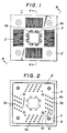
- Fig. 1 shows a plan view of a connector 1 for an electric part, which has a plurality of contacts 3 arranged on a connector board 2 and adapted to contact with an electric part.
- Each of the contacts 3 has a leg portion 3a which projects outward from the connector board 2 so as to be connected with a wiring board 5.
- a projection surface of the connector board 2 from which the leg portions 3a project is provided with a locator 4 as shown in Fig. 3.
- the locator 4 is provided with a plurality of leg portion guide holes 4a of the plate type adapted to receive the leg portions 3a and correctly position them.
- the locator 4 is further provided with temporarily fixing means for temporarily fixing the locator 4 in a position away from the leg projection surface of the connector board 2.
- the temporarily fixing means is provided with an engagement means disposed between the locator 4 and the connector board 2 and adapted to engage in a male and female engagement fashion at the position away from the connector board 2 and the locator 4 escapes and allowed to move when the engagement means exerts a compulsive moving force to the locator 4 in the approaching direction.
- locator 4 is provided at a generally central portion thereof Wi th a plurality of depart stoppers 4b and approach stoppers 4c, all erected therefrom.
- the depart stoppers 4b are engaged with the connector board 2 as such that the locator 4 is permitted to move in the approaching direction and prohibited to move in the departing direction, while the approach stoppers 4c are abutted against the connector board 2 as such that the locator 4 is restricted to move in the approaching direction, thereby to depart the locator 4 by a predetermined length from the connector board 2 and the vicinities of the tip portions of the leg portions 3a of the contacts 3 are shallowly inserted into the guide holes 4a of the plate type of the locator 4 in order to correctly position to realize a temporarily fixed state. In the foregoing state, the locator 4 is correctly positioned relative to the wiring board 5. As is shown in Fig.
- the depart stoppers 4b prevents the movement in the departing direction in such a manner as that engaging claws formed on the tips of the depart stoppers 4b are engaged with a retaining step portion 2a of the connector board 2.
- the approach stoppers 4c are brought into abutment with the connector board 2 while the depart stoppers 4b are in engagement with the connector board 2 and by exerting a compulsive force in the direction opposite to the engaging direction, it is permitted to climb over and allowed to move in the approaching direction to the connector board 2.
- the projection 4f disposed at the tip of the approach stopper is abutted with the projection 2b formed on the connector board 2, and both the projections 4f and 2b are slipped to cancel the abutment engagement.
- the slip projections 4f and 2b are formed, for example, in a hill shape or arcuate shape having tapered upper and lower surfaces.
- the locator 4 can be moved between a first position close to the connector board 2 and a second position away from the connector board 2.
- the locator 4 is temporarily fixed in the second position away from the connector board 2 as shown in Fig. 4(A).
- the leg portions 3a are inserted into the connection holes 5a of the wiring board 5.
- Figs. 5 through 6 show another embodiment of the connector 1 for an electric part.
- positioning pins 6 to be inserted into the connecting holes 5a of the wiring board 5 are arranged on a projection surface of the locator 4 from which the leg portions 3a project.
- Each of the positioning pins 6 engage at its central portion with a fixing screw hole 7 penetrating the locator 4.
- the locator 4 is provided in the vicinity of its central portion with a reinforcing projection escape hole 8.
- the connector board 2 is provided in a position corresponding to the fixing screw hole 7 with a fixing screw insertion hole 9 in such a manner as to penetrate the board 2 and in a position corresponding to the reinforcing projection escape hole 8 with a reinforcing projection 10.
- the positioning pin 6 is set as such that when the locator 4 is temporarily fixed in the second position away from the connector board 2, the tip of the positioning pin 6 is in a position (distant position) spaced apart from the tip of the leg portion 3a. Accordingly, when the locator 4 is inserted into the connecting hole 5a of the wiring board 5 and correctly positioned by the positioning pin 6, the inserting work of the leg portion can be performed without having the tip of the leg portion 3a contacted with the wiring board 5.
- the reinforcing projection 10 contacts with the wiring board 5 in the vicinity of its central portion through the escape hole 8 of the locator 4, so that the strength of the wiring board 5 can also be utilized.
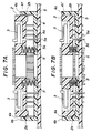
- Figs. 7(A) and 7(B) show still another embodiment of a connector 1 for an electric part according to the present invention.
- a coil spring 11 is interposed between the locator 4 and the connector board 2, and the depart stopper 4b is disposed in such a manner as to be able to engage With the outer peripheral portion of the connector board 2. That is, the locator 4 and the connector board 2 are separated away by a biasing force of the coil spring 11 and the locator 4 is temporarily fixed in a position away from the connector board 2 because the depart stopper 4b is engaged with the locator 4 in a position away from the connector board 2 by a predetermined distance.
- Figs. 8(A) and 8(B) show yet another embodiment of a connector 1 for an electric part according to the present invention.
- the depart stopper 4b and the approach stopper 4c are formed as one body engageable with the outer peripheral portion of the connector 1 for an electric part.
- the locator 4 is provided with temporarily fixing elements 4′ each erected from one end and the other end of the locator 4 and each of the temporarily fixing elements is provided with an engaging projection 4g.
- a side surface of one end of the connector board 2 and a side surface of the other end are provided with a recess portion 2c respectively so that the engaging projection 4g can be engaged in the corresponding recess portion 2c.
- Fig. 8(A) when the engaging projection 4g is in engagement with the recess portion 2c, the second position of the locator 4 away from the connector board 2 is maintained and the engaging projection 4g escapes from the engaging recess portion 2c for permitting the locator 4 to move in the approaching direction.
- the locator 4 When the locator 4 is temporarily fixed to or resiliently held in the second position away from the connector board 2, at least two leg portions 3a project from the leg portion guide holes 4a of the locator 4. Otherwise, the tip of the leg portion 3a is shallowly inserted in the leg portion guide hole 4a such that the tip does not project therefrom or the tip of the leg portion 3a is held in a position immediately before inserting into the guide hole 4a. And in the foregoing state, the locator 4 is temporarily fixed or resiliently held.
- the tip position of the leg portion can be reliably restricted by the locator temporarily fixed to or resiliently held in the position away from the connector board. Also, by holding the locator in its horizontal state by means of the afore-mentioned temporary fixing or resilient holding arrangement, the mounting work of the connector for an electric part to the printed circuit board can be performed correctly and rapidly.
- the positioning pin for correctly positioning the locator to the wiring board, the mounting work can be simplified, and the wiring of the printed circuit board is not scratched and cut off when the contact leg portions are inserted.
- the above-mentioned improvement can be obtained without forming extra holes in the printed circuit board, and the degree of freedom of wiring patterns of the printed circuit board is not lost, either.
Landscapes
- Engineering & Computer Science (AREA)
- Microelectronics & Electronic Packaging (AREA)
- Manufacturing & Machinery (AREA)
- Coupling Device And Connection With Printed Circuit (AREA)
- Connecting Device With Holders (AREA)
- Multi-Conductor Connections (AREA)
Claims (7)
- Verbinder zum Anschließen eines elektrischen Teiles an eine Leiterplatte (5), bestehend aus einer Anschlußplatte (2) mit aus der Platte (2) vorspringenden Steckerstiften (3a) einer Mehrzahl von der Platte (2) zugeordneten Kontakten (3) mit einem mit Durchgängen (4a) für die Steckerstifte (3a) versehenen Führungsstück (4), dessen Durchgänge (4a) von den Steckerstiften (3a) individuell mit Überstand für die Herstellung der Anschlüsse an der Leiterplatte (5) durchsetzt werden, gekennzeichnet durch ein aus seiner unmittelbaren Anlage gegen die Anschlußplatte (2) in eine von der Anschlußplatte (2) beabstandete Position verlagerbares Führungsstück (4) und Fixierungsmittel zur vorübergehenden Festlegung des Führungsstücks (4) in seiner beabstandeten Position zur Anschlußplatte (2).
- Verbinder zum Anschließen eines elektrischen Teiles an eine Leiterplatte (5), bestehend aus einer Anschlußplatte (2) mit aus der Platte (2) vorspringenden Steckerstiften (3a) einer Mehrzahl von der Platte (2) zugeordneten Kontakten (3) mit einem mit Durchgängen (4a) für die Steckerstifte (3a) versehenen Führungsstück (4), dessen Durchgänge (4a) von den Steckerstiften (3a) individuell mit Überstand für die Herstellung der Anschlüsse an der Leiterplatte (5) durchsetzt werden, gekennzeichnet durch ein aus seiner unmittelbaren Anlage der Anschlußplatte (2) in eine von der Anschlußplatte (2) beabstandete Position verlagerbares, in der zur Anschlußplatte (2) beabstandeten Position durch Federkraft fixierbares Führungsstück (4).
- Verbinder zum Anschließen eines elektrischen Teils nach Anspruch 1 oder Anspruch 2, dadurch gekennzeichnet, daß mindestens zwei Steckerstifte (3a) eine Länge aufweisen, aus der sich ein Überstand der Steckerstifte (3a) über das Führungsstück (4) der beabstandeten Positionierung des Führungsstücks (4) zur Anschlußplatte (2) ergibt.
- Verbinder zum Anschließen eines elektrischen Teils nach Anspruch 1, dadurch gekennzeichnet, daß sämtliche Steckerstifte (3a) eine Länge aufweisen, aus der eine beabstandete Positionierung des Führungsstücks (4) zur Anschlußplatte (2) ohne Steckerstift-Überstand resultiert.
- Verbinder zum Anschließen eines elektrischen Teils nach einem der Ansprüche 1 bis 4, dadurch gekennzeichnet, daß das Führungsstück (4) auf der der Leiterplatte (5) zugewandten Seite mit einer Mehrzahl von über es vorspringenden Positionierungstiften (6) zur eindeutigen Zuordnung des Führungsstücks (4) zur Leiterplatte (5) versehen ist.
- Verbinder zum Anschließen eines elektrischen Teils nach Anspruch 5, gekennzeichnet durch die Positionierungsstifte (6) durchsetzende Schrauben (12) zur Festlegung der Anschlußplatte (2) gegenüber der Leiterplatte (5).
- Verbinder zum Anschließen eines elektrischen Teils nach Anspruch 5 oder Anspruch 6, dadurch gekennzeichnet, daß die Positionierungsstifte (6) eine Länge aufweisen, aus der - bei beabstandeter Positionierung des Führungsstücks (4) zur Anschlußplatte (2) - ein größerer Überstand der Positionierungsstifte (6) über das Führungsstück (4) als der der Steckerstifte (3a) resultiert.
Applications Claiming Priority (2)
| Application Number | Priority Date | Filing Date | Title |
|---|---|---|---|
| JP295438/89 | 1989-11-14 | ||
| JP1295438A JP2681109B2 (ja) | 1989-11-14 | 1989-11-14 | 電気部品用接続器 |
Publications (2)
| Publication Number | Publication Date |
|---|---|
| EP0428359A1 EP0428359A1 (de) | 1991-05-22 |
| EP0428359B1 true EP0428359B1 (de) | 1994-09-14 |
Family
ID=17820597
Family Applications (1)
| Application Number | Title | Priority Date | Filing Date |
|---|---|---|---|
| EP90312326A Expired - Lifetime EP0428359B1 (de) | 1989-11-14 | 1990-11-12 | Verbinder für elektrische Teile |
Country Status (7)
| Country | Link |
|---|---|
| US (1) | US5078626A (de) |
| EP (1) | EP0428359B1 (de) |
| JP (1) | JP2681109B2 (de) |
| KR (1) | KR0173120B1 (de) |
| CA (1) | CA2029844A1 (de) |
| DE (1) | DE69012514D1 (de) |
| MY (1) | MY105390A (de) |
Families Citing this family (25)
| Publication number | Priority date | Publication date | Assignee | Title |
|---|---|---|---|---|
| JPH0438693U (de) * | 1990-07-31 | 1992-03-31 | ||
| JPH0587877U (ja) * | 1992-04-30 | 1993-11-26 | 住友電装株式会社 | コネクタ端子検査装置 |
| US5348488A (en) * | 1993-04-09 | 1994-09-20 | The Whitaker Corporation | Electrical connector with board-mounting alignment system |
| JPH07235351A (ja) * | 1994-02-21 | 1995-09-05 | Kel Corp | プリント基板用コネクタ |
| US5540598A (en) * | 1994-06-16 | 1996-07-30 | The Whitaker Corporation | Pin spacer for an electrical connector |
| EP0860039B1 (de) * | 1995-11-06 | 2000-03-01 | The Whitaker Corporation | Koppler für elektrische verbinder |
| JP3644553B2 (ja) * | 1995-11-20 | 2005-04-27 | 株式会社アドバンテスト | Icソケット |
| JP3106957B2 (ja) * | 1996-05-27 | 2000-11-06 | 住友電装株式会社 | 基板用コネクタ |
| TW400666B (en) * | 1997-01-29 | 2000-08-01 | Furukawa Electric Co Ltd | IC socket |
| US6273732B1 (en) | 1999-06-18 | 2001-08-14 | Berg Technology, Inc. | Through mount connector with alignment device |
| JP3934334B2 (ja) | 1999-12-22 | 2007-06-20 | 矢崎総業株式会社 | プリント回路基板接続用コネクタ |
| JP2001185267A (ja) | 1999-12-22 | 2001-07-06 | Yazaki Corp | プリント回路基板接続用コネクタ |
| US6866552B2 (en) * | 2003-02-21 | 2005-03-15 | Molex Incorporated | Electrical connector with a terminal pin alignment plate |
| US7101211B2 (en) * | 2004-04-27 | 2006-09-05 | Hewlett-Packard Development Company, L.P. | Shroud for pin and socket connection |
| JP4457927B2 (ja) * | 2005-03-14 | 2010-04-28 | 住友電装株式会社 | コネクタ |
| JP2007194434A (ja) * | 2006-01-19 | 2007-08-02 | Fujitsu Ltd | 実装材整列基板、実装装置、実装方法及び回路基板製造方法 |
| JP2007194435A (ja) * | 2006-01-19 | 2007-08-02 | Fujitsu Ltd | 実装材整列基板、実装装置、実装方法及び回路基板製造方法 |
| US7491096B1 (en) * | 2007-07-31 | 2009-02-17 | Phoenix Contact Development & Manufacturing Inc. | Modular terminal block |
| CN201207454Y (zh) * | 2008-04-21 | 2009-03-11 | 富士康(昆山)电脑接插件有限公司 | 电连接器 |
| US8408923B2 (en) * | 2010-08-26 | 2013-04-02 | J. S. T. Corporation | Dielectric part and an electrical connector assembly incorporating the same |
| JP5647876B2 (ja) * | 2010-11-30 | 2015-01-07 | 株式会社エンプラス | 電気部品用ソケット |
| JP5644657B2 (ja) * | 2011-05-10 | 2014-12-24 | 住友電装株式会社 | 車載用電気機器のシールカバー |
| JP5645081B2 (ja) * | 2011-05-10 | 2014-12-24 | 住友電装株式会社 | 車載用電気機器のシールカバー |
| DE102014204051A1 (de) * | 2014-03-05 | 2015-09-10 | Robert Bosch Gmbh | Verbindungsanordnung, Verfahren zum Herstellen einer Verbindungsanordnung und elektrisches Gerät mit einer Verbindungsanordnung |
| US10027051B1 (en) * | 2017-02-20 | 2018-07-17 | Robert Bosch Gmbh | Hybrid electrical connector |
Family Cites Families (10)
| Publication number | Priority date | Publication date | Assignee | Title |
|---|---|---|---|---|
| US4060296A (en) * | 1976-10-26 | 1977-11-29 | Amp Incorporated | Low profile DIP receptacle |
| JPS5855576Y2 (ja) * | 1980-05-07 | 1983-12-20 | クラリオン株式会社 | コネクタ−固定装置 |
| US4490001A (en) * | 1983-02-07 | 1984-12-25 | Matsushita Electric Industrial Co., Ltd. | Dip carrier and socket |
| FR2552590B1 (fr) * | 1983-09-23 | 1986-03-28 | Nalbanti Georges | Support de boitier de circuit integre |
| JPS60147189U (ja) * | 1984-03-12 | 1985-09-30 | オムロン株式会社 | ラツピングタイプ・コネクタの実装構造 |
| US4739257A (en) * | 1985-06-06 | 1988-04-19 | Automated Electronic Technology, Inc. | Testsite system |
| JPH0517828Y2 (de) * | 1986-10-14 | 1993-05-12 | ||
| US4713014A (en) * | 1986-12-23 | 1987-12-15 | Hughes Aircraft Company | Quick-release multi-module terminating assembly |
| FR2618951B1 (fr) * | 1987-07-28 | 1994-01-28 | Metallo Ste Fse | Connecteur pour tubes cathodiques tels que prevus pour la television pourvu d'une semelle telescopique destinee a assurer la protection totale des sorties de contact durant le stockage, le transport et la manutention jusqu'a son insertion aussi bien manuelle qu'automatique dans le circuit imprime |
| JPH01132076U (de) * | 1988-03-04 | 1989-09-07 |
-
1989
- 1989-11-14 JP JP1295438A patent/JP2681109B2/ja not_active Expired - Fee Related
-
1990
- 1990-11-12 DE DE69012514T patent/DE69012514D1/de not_active Expired - Lifetime
- 1990-11-12 EP EP90312326A patent/EP0428359B1/de not_active Expired - Lifetime
- 1990-11-13 MY MYPI90001997A patent/MY105390A/en unknown
- 1990-11-13 CA CA002029844A patent/CA2029844A1/en not_active Abandoned
- 1990-11-14 KR KR1019900018412A patent/KR0173120B1/ko not_active Expired - Fee Related
- 1990-11-14 US US07/613,984 patent/US5078626A/en not_active Expired - Lifetime
Also Published As
| Publication number | Publication date |
|---|---|
| EP0428359A1 (de) | 1991-05-22 |
| MY105390A (en) | 1994-09-30 |
| JPH03155082A (ja) | 1991-07-03 |
| KR910011113A (ko) | 1991-06-29 |
| US5078626A (en) | 1992-01-07 |
| KR0173120B1 (ko) | 1999-05-01 |
| DE69012514D1 (de) | 1994-10-20 |
| CA2029844A1 (en) | 1991-05-15 |
| JP2681109B2 (ja) | 1997-11-26 |
Similar Documents
| Publication | Publication Date | Title |
|---|---|---|
| US5078626A (en) | Connector for electric parts | |
| EP0045153B1 (de) | Endkontakt für die Montage auf einer Leiterplatte | |
| US5073119A (en) | Surface mount electrical connector | |
| JPH07235351A (ja) | プリント基板用コネクタ | |
| US4826447A (en) | Snap board retainer | |
| JPH0973950A (ja) | 可動コネクタ | |
| JP2514650B2 (ja) | コネクタ | |
| US6328589B1 (en) | Electrical connector | |
| JPH09298074A (ja) | エッジコネクタ | |
| CA1262289A (en) | Ic insertion/extraction tool | |
| EP1146605B1 (de) | Steckverbinder | |
| JPH0668940A (ja) | Fpc接続用コネクタ | |
| CN100477413C (zh) | 用于针栅阵列插件的插座 | |
| EP1102358B1 (de) | Fassung für elektronische Bauteile | |
| KR20020034877A (ko) | 기판취부형 커넥터 및 커넥터의 기판취부구조 | |
| EP0819324A1 (de) | Verbinder für flexible leiterplatte | |
| US4826441A (en) | Test board connectors and method for attaching | |
| KR200225804Y1 (ko) | 안내 부재와 센터링 부재가 포함된 플러그형 전기 커넥터 | |
| USRE39230E1 (en) | IC socket for electrical parts with improved electrical contact | |
| JP2002151187A (ja) | 可動型コネクタ | |
| JPH0570273B2 (de) | ||
| KR20190059331A (ko) | 프레스 핏 단자 | |
| JPH03694Y2 (de) | ||
| JP2669409B2 (ja) | Zip用icソケット | |
| JP2545049Y2 (ja) | 電気コネクタのプリント配線板に対する止着手段 |
Legal Events
| Date | Code | Title | Description |
|---|---|---|---|
| PUAI | Public reference made under article 153(3) epc to a published international application that has entered the european phase |
Free format text: ORIGINAL CODE: 0009012 |
|
| AK | Designated contracting states |
Kind code of ref document: A1 Designated state(s): DE FR GB IT |
|
| 17P | Request for examination filed |
Effective date: 19910617 |
|
| 17Q | First examination report despatched |
Effective date: 19931013 |
|
| GRAA | (expected) grant |
Free format text: ORIGINAL CODE: 0009210 |
|
| RAP1 | Party data changed (applicant data changed or rights of an application transferred) |
Owner name: YAMAICHI ELECTRONICS CO., LTD. |
|
| AK | Designated contracting states |
Kind code of ref document: B1 Designated state(s): DE FR GB IT |
|
| PG25 | Lapsed in a contracting state [announced via postgrant information from national office to epo] |
Ref country code: IT Free format text: LAPSE BECAUSE OF FAILURE TO SUBMIT A TRANSLATION OF THE DESCRIPTION OR TO PAY THE FEE WITHIN THE PRE;WARNING: LAPSES OF ITALIAN PATENTS WITH EFFECTIVE DATE BEFORE 2007 MAY HAVE OCCURRED AT ANY TIME BEFORE 2007. THE CORRECT EFFECTIVE DATE MAY BE DIFFERENT FROM THE ONE RECORDED.SCRIBED TIME-LIMIT Effective date: 19940914 |
|
| ET | Fr: translation filed | ||
| REF | Corresponds to: |
Ref document number: 69012514 Country of ref document: DE Date of ref document: 19941020 |
|
| PG25 | Lapsed in a contracting state [announced via postgrant information from national office to epo] |
Ref country code: DE Effective date: 19941215 |
|
| RAP4 | Party data changed (patent owner data changed or rights of a patent transferred) |
Owner name: YAMAICHI ELECTRONICS CO., LTD. |
|
| PLBE | No opposition filed within time limit |
Free format text: ORIGINAL CODE: 0009261 |
|
| STAA | Information on the status of an ep patent application or granted ep patent |
Free format text: STATUS: NO OPPOSITION FILED WITHIN TIME LIMIT |
|
| PG25 | Lapsed in a contracting state [announced via postgrant information from national office to epo] |
Ref country code: FR Effective date: 19950731 |
|
| 26N | No opposition filed | ||
| REG | Reference to a national code |
Ref country code: FR Ref legal event code: ST |
|
| PGFP | Annual fee paid to national office [announced via postgrant information from national office to epo] |
Ref country code: GB Payment date: 19951102 Year of fee payment: 6 |
|
| PG25 | Lapsed in a contracting state [announced via postgrant information from national office to epo] |
Ref country code: GB Effective date: 19961112 |
|
| GBPC | Gb: european patent ceased through non-payment of renewal fee |
Effective date: 19961112 |