EP0428844A2 - Rolladenpanzer für Kastenmöbel - Google Patents
Rolladenpanzer für Kastenmöbel Download PDFInfo
- Publication number
- EP0428844A2 EP0428844A2 EP90117517A EP90117517A EP0428844A2 EP 0428844 A2 EP0428844 A2 EP 0428844A2 EP 90117517 A EP90117517 A EP 90117517A EP 90117517 A EP90117517 A EP 90117517A EP 0428844 A2 EP0428844 A2 EP 0428844A2
- Authority
- EP
- European Patent Office
- Prior art keywords
- roller shutter
- profile
- individual profiles
- base
- shutter curtain
- Prior art date
- Legal status (The legal status is an assumption and is not a legal conclusion. Google has not performed a legal analysis and makes no representation as to the accuracy of the status listed.)
- Granted
Links
Images
Classifications
-
- E—FIXED CONSTRUCTIONS
- E06—DOORS, WINDOWS, SHUTTERS, OR ROLLER BLINDS IN GENERAL; LADDERS
- E06B—FIXED OR MOVABLE CLOSURES FOR OPENINGS IN BUILDINGS, VEHICLES, FENCES OR LIKE ENCLOSURES IN GENERAL, e.g. DOORS, WINDOWS, BLINDS, GATES
- E06B9/00—Screening or protective devices for wall or similar openings, with or without operating or securing mechanisms; Closures of similar construction
- E06B9/02—Shutters, movable grilles, or other safety closing devices, e.g. against burglary
- E06B9/08—Roll-type closures
- E06B9/11—Roller shutters
- E06B9/15—Roller shutters with closing members formed of slats or the like
-
- E—FIXED CONSTRUCTIONS
- E06—DOORS, WINDOWS, SHUTTERS, OR ROLLER BLINDS IN GENERAL; LADDERS
- E06B—FIXED OR MOVABLE CLOSURES FOR OPENINGS IN BUILDINGS, VEHICLES, FENCES OR LIKE ENCLOSURES IN GENERAL, e.g. DOORS, WINDOWS, BLINDS, GATES
- E06B9/00—Screening or protective devices for wall or similar openings, with or without operating or securing mechanisms; Closures of similar construction
- E06B9/02—Shutters, movable grilles, or other safety closing devices, e.g. against burglary
- E06B9/08—Roll-type closures
- E06B9/11—Roller shutters
- E06B9/115—Roller shutters specially adapted for furniture
-
- E—FIXED CONSTRUCTIONS
- E06—DOORS, WINDOWS, SHUTTERS, OR ROLLER BLINDS IN GENERAL; LADDERS
- E06B—FIXED OR MOVABLE CLOSURES FOR OPENINGS IN BUILDINGS, VEHICLES, FENCES OR LIKE ENCLOSURES IN GENERAL, e.g. DOORS, WINDOWS, BLINDS, GATES
- E06B9/00—Screening or protective devices for wall or similar openings, with or without operating or securing mechanisms; Closures of similar construction
- E06B9/02—Shutters, movable grilles, or other safety closing devices, e.g. against burglary
- E06B9/08—Roll-type closures
- E06B9/11—Roller shutters
- E06B9/15—Roller shutters with closing members formed of slats or the like
- E06B2009/1533—Slat connections
- E06B2009/155—Slats connected by separate elements
- E06B2009/1555—Flexible elements, e.g. tapes, strips, cords or chains
Definitions
- the innovation relates to a roller shutter curtain for cabinet furniture, consisting of individual profiles with connecting means for articulated fastening of the individual profiles to one another.
- roller shutters with individual profiles are known in multiple embodiments.
- DE-AS 21 11 317 describes a roller shutter hollow profile rod made of extruded plastic, the cross-section of which consists of at least one self-contained chamber with two main walls curved in the same direction and spaced a short distance apart. The centers of curvature lie on the side facing the roller shutter roller.
- the main walls are connected to one another by connecting webs, one of the connecting webs having a hook bent toward the roller shutter roller, while an articulated chamber provided with a suspension slot for the hook of the adjacent profile bar is formed on the other connecting web.
- the curvature of the main walls and the articulation of the slot-hook connections determine the size of the winding radius of the roller shutter element.
- roller shutters constructed in this way, both window and cabinet openings can be closed.
- roller shutters are also known from the prior art, which are constructed from a rollable laminate with transverse stiffeners arranged transversely to the rolling direction. DE-U 79 13 550 is mentioned as an example of this.
- Cabinet roller shutters constructed in this way have the disadvantage that their manufacture must be carried out individually for the individual application. A subsequent change, for example an extension, is no longer possible with this manufacturing method.
- the use of the roller shutter element according to the invention has the advantage that the overall lengths of the roller shutter can be varied as desired.
- the roller shutter element once manufactured can be easily adapted to the required sizes by joining several such elements together.
- the individual profiles are advantageously trapezoidal hollow bars, on the narrower base of which, facing away from the visible side, the film hinges are arranged as profile-connecting polymer bridges. Furthermore, the individual profiles on the profile legs in the contact area have on the one hand a profile thickening and on the other hand a profile constriction for receiving the assigned profile thickening. This measure causes the roller shutter curtain to additionally solidify in the closed state.
- the groove opening for connecting two new roller shutter elements to one another is advantageously embedded in the base of the external hollow bar. It is advantageous for the overall structure that the base of the outer hollow rod is set back by its wall thickness. In the manufacture of the roller shutter element, the wall thickness of the hollow rod is equated with the wall thickness of the profile carrying the spring. In this way, with the production of the tongue-and-groove connection, a connection profile which corresponds in scope to the other individual profiles of the roller shutter element is created.
- the hollow rod with the groove opening can have an inner reinforcing web connecting the profile legs.
- the tongue profile required to produce the tongue and groove connection is a mushroom-like locking element that protrudes from its base and is thicker in the area of its largest projection than the clear passage of the slot opening.
- the dimensions of this mushroom-like locking element can be designed such that it can be pressed into the groove opening of the associated hollow connecting rod or drawn in laterally.
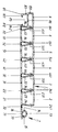
- the innovative roller shutter element 1 is shown in cross section.
- the roller shutter element shown has five individual sections 2, 3, 4, 5, 6 of the same size. These individual sections 2, 3, 4, 5, 6 are at their bases 21, 31, 41, 51, 61 each via the film hinges 22, 32, 42 , 52 firmly connected. This connection takes place in the primary molding process during the manufacture of the individual profiles.
- the manufacturing process known as coextrusion is used, in which, for example, plastics of different hardness settings are connected to one another in one operation.
- the individual profiles 2, 3, 4, 5, 6 have a profile thickening 231, 331, 431, 531, 631 in the contact area with one another.
- the individual profiles 2, 3, 4, 5, 6 at the same height of the profile thickenings 231, 331, 431, 531, 631 have a constriction 241, 341, 441, 541, 641 designed accordingly.
- the profile thickenings 231, 331, 431, 531 lie in the profile constrictions 341, 441, 541, 641.
- the base 71 of the spring profile 7 is articulated to the base 21 of the individual profile 2 via the film hinge 72.
- the spring profile 7 is a mushroom head-like locking element with a rounded head 73 and from the areas of the largest projection 74, 75 to the base 71 there are connecting webs 76, 77 which run in a straight line towards one another.
- the illustration shown serves only as an example for the construction of such a locking element. Other cross-sectional shapes of these grids with the same properties are considered to be covered by the property right.
- the profile 8 containing the slot opening 85 is firmly articulated to the individual profile 6 via the film hinge 82.
- the groove opening 85 is let into the base 81 of the profile 8 so that the base webs 811, 812 delimit the groove opening 85.
- the base 81 of the profile 8 is set back by the wall thickness of the base 71 of the profile 7 to the interior of the profile 8, the web area 842 to which the film hinge 82 is articulated has been left standing.
- the profile constriction 841 is embedded in the profile leg 84, in which the profile thickening 631 of the preceding individual profile 6 engages in the illustration shown.
- the profile thickening 831 is integrally formed on the opposite profile leg 83, which engages in the corresponding profile constriction of the assigned individual profile of an arranged second roller shutter element, not shown in the drawing.
- the profile 8 has an inner reinforcement web 86 connecting the profile legs 83, 84. This reinforcement web 86 serves to increase the strength of the profile 8.
Landscapes
- Engineering & Computer Science (AREA)
- Structural Engineering (AREA)
- Architecture (AREA)
- Civil Engineering (AREA)
- Operating, Guiding And Securing Of Roll- Type Closing Members (AREA)
- Hinges (AREA)
- Cabinets, Racks, Or The Like Of Rigid Construction (AREA)
- Securing Of Glass Panes Or The Like (AREA)
- Specific Sealing Or Ventilating Devices For Doors And Windows (AREA)
- Transition And Organic Metals Composition Catalysts For Addition Polymerization (AREA)
- Compositions Of Macromolecular Compounds (AREA)
- Ink Jet (AREA)
- Shutters For Cameras (AREA)
- Crystals, And After-Treatments Of Crystals (AREA)
Abstract
Description
- Die Neuerung betrifft einen Rolladenpanzer für Kastenmöbel, bestehend aus Einzelprofilen mit Verbindungsmitteln zum gelenkigen Befestigen der Einzelprofile aneinander.
- Rolladen mit Einzelprofilen sind in vielfachen Ausführungsformen bekannt. So beschreibt die DE-AS 21 11 317 einen Rolladen-Hohlprofilstab aus stranggepresstem Kunststoff, den Querschnitt aus mindestens einer in sich geschlossenen Kammer mit zwei gleichsinnig gekrümmten, in geringem Abstand zueinander angeordneten Hauptwandungen besteht. Die Krümmungsmittelpunkte liegen dabei auf der der Rolladenwalze zugewandten Seite. Die Hauptwandungen sind durch Verbindungsstege miteinander verbunden, wobei einer der Verbindungsstege einen zur Rolladenwalze abgebogenen Haken aufweist, während an dem anderen Verbindungssteg eine mit einem Einhängeschlitz für den Haken des benachbarten Profilstabes versehene Gelenkkammer angeformt ist. Die Krümmung der Hauptwandungen und die Gelenkigkeit der Schlitz-Hakenverbindungen bestimmen bei diesem bekannten Stand der Technik die Größe des Aufwickelradius des Rolladenelements. Mit derart aufgebauten Rolläden können sowohl Fenster- als auch Schranköffnungen verschlossen werden. Speziell für den Verschluß von Schranköffnungen sind nach dem Stand der Technik weiterhin Rolladen bekannt, welche aus einer rollfähigen Schichtstoffplatte mit quer zur Rollrichtung angeordneten Querversteifungen aufgebaut sind. Als Beispiel hierfür wird die DE-U 79 13 550 genannt. Derart aufgebaute Schrankrolläden haben den Nachteil, daß ihre Herstellung jeweils individuell für den einzelnen Anwendungsfall erfolgen muß. Eine nachträgliche Veränderung, z.B. eine Verlängerung, ist bei dieser Herstellungsmethode nicht mehr möglich.
- Hier setzt die Neuerung ein, die es sich zur Aufgabe gestellt hat, einen Rolladen für den Schrank- bzw. Möbelbau anzugeben, der aufbauend auf den Erkenntnissen des Standes der Technik auch eine nachträgliche Anpassung an die Vielzahl der gegebenen Einsatzmöglichkeiten beinhaltet.
- Neuerungsgemäß wird dazu vorgeschlagen, daß mehrere Einzelprofile über Filmscharniere zu einem Rolladenelement verbunden sind, und daß an den freien Enden jedes Rolladenelementes einerseits ein Profil mit einer Nutenöffnung und andererseits ein Profil mit einer Feder zum Festlegen zweier Rolladenelemente aufeinander angeformt sind.
- Die fertigungstechnische Zusammenfassung mehrerer Einzelprofile zu einem Rolladenelement, wobei die Einzelprofile jeweils über Filmscharniere miteinander verbunden sind, ergibt eine Arbeitserleichterung bei der Montage, verbunden mit einer erheblichen Zeiteinsparung. Anstelle des Einfädelns der Hakenstege in die zugeordneten Schlitzöffnungen der Folgeprofile bei jedem Einzelprofil muß dieser zeitaufwendige Arbeitsgang bei Verarbeitung des neuerungsgemäßen Rolladenelementes nur noch im Rahmen der Herstellungsbreiten dieser Rolladenelemente ausgeführt werden.
- Gegenüber den bekannten Rolladenelementen mit rollfähigen Folien und Querversteifungen bringt die Anwendung des neuerungsgemäßen Rolladenelementes den Vorteil, daß die Baulängen des Rolladens beliebig variiert werden können. Das einmal gefertigte Rolladenelement kann durch beliebiges Aneinanderfügen mehrerer solcher Elemente den erforderlichen Baugrößen ohne weiteres angepaßt werden.
- Vorteilhaft sind die Einzelprofile trapezartige Hohlstäbe, an deren schmalerer, von der Sichtseite abgewandten Basis die Filmscharniere als profilverbindende Polymerbrücken angeordnet sind. Ferner besitzen die Einzelprofile an den Profilschenkeln im Anlagebereich einerseits eine Profilverdikkung und andererseits eine Profileinschnürung zur Aufnahme der zugeordneten Profilverdickung. Durch diese Maßnahme wird eine zusätzliche Verfestigung des Rolladenpanzers in geschlossenem Zustand bewirkt.
- Die Nutenöffnung für die Verbindung zweier neuerungsgemäßer Rolladenelemente miteinander ist vorteilhaft in die Basis des außenliegenden Hohlstabes eingelassen. Hierbei ist es für den Gesamtaufbau günstig, daß die Basis des außenliegenden Hohlstabes um seine Wanddicke zurückversetzt ist. Die Wanddicke des Hohlstabes wird bei der Herstellung des Rolladenelementes gleichgesetzt mit der Wanddicke des die Feder tragenden Profils. Auf diese Weise wird mit der Herstellung der Nut-Feder-Verbindung ein im Umfang den anderen Einzelprofilen des Rolladenelementes völlig entsprechendes Verbindungsprofil geschaffen.
- Zur zusätzlichen Verfestigung kann der Hohlstab mit der Nutenöffnung einen die Profilschenkel verbindenden inneren Verstärkungssteg aufweisen.
- Das zur Herstellung der Nut-Feder-Verbindung erforderliche Federprofil ist ein von seiner Basis abragendes, pilzkopfartiges Rastelement, welches im Bereich seiner größten Ausladung dicker ist als der lichte Durchgang der Nutenöffnung. Dieses pilzkopfartige Rastelement kann von seinen Abmessungen her so gestaltet sein, daß es in die Nutenöffnung des zugeordneten Verbindungshohlstabes eingedrückt oder seitlich eingezogen werden kann.
- In diesem Zustand hintergreifen die aufeinanderzu gerichteten freien Enden der die Nutenöffnung begrenzenden Wandbereiche der Basis eines außenliegenden Hohlstabes, die Außenbereiche des zugeordneten pilzkopfartigen Rastelementes in Form einer festen Halterung.
- In der Zeichnung ist das neuerungsgemäße Rolladenelement 1 im Querschnitt dargestellt. Das gezeigte Rolladenelement besitzt fünf gleichgroße Einzelprofile 2, 3, 4, 5, 6. Diese Einzelprofile 2, 3, 4, 5, 6 sind an ihrer Basis 21, 31, 41, 51, 61 jeweils über die Filmscharniere 22, 32, 42, 52 fest miteinander verbunden. Diese Verbindung erfolgt im Urformprozess bei der Herstellung der Einzelprofile. Hierzu wird das als Koextrusion bekannte Herstellungsverfahren angewendet, bei dem beispielsweise Kunststoffe verschiedener Härteeinstellungen in einem Arbeitsgang miteinander verbunden werden.
- An den Profilschenkeln 23, 33, 43, 53, 63 besitzen die Einzelprofile 2, 3, 4, 5, 6 im Anlagebereich zueinander eine Profilverdickung 231, 331, 431, 531, 631. An den gegenüberliegenden Profilschenkeln 24, 34, 44, 54, 64 besitzen die Einzelprofile 2, 3, 4, 5, 6 auf der gleichen Höhe der Profilverdickungen 231, 331, 431, 531, 631 eine diesen entsprechend gestaltete Profileinschnürung 241, 341, 441, 541, 641. In dem in der Zeichnung dargestellten geschlossenen Zustand liegen die Profilverdickungen 231, 331, 431, 531 in den Profileinschnürungen 341, 441, 541, 641.
- An die Basis 21 des Einzelprofils 2 ist über das Filmscharnier 72 die Basis 71 des Federprofils 7 angelenkt.
- Das Federprofil 7 ist ein pilzkopfartiges Rastelement mit abgerundetem Kopf 73 und von den Bereichen der größten Ausladung 74, 75 zur Basis 71 gradlinig aufeinanderzu laufenden Verbindungsstegen 76, 77 besteht. Die gezeigte Darstellung dient lediglich als Beispiel für den Aufbau eines solchen Rastelementes. Andere Querschnittsformen dieser Raster mit gleichen Eigenschaften werden als unter das Schutzrecht fallend angesehen.
- Am gegenüberliegenden Ende des gezeigten Rolladenelementes 1 ist über das Filmscharnier 82 das die Nutenöffnung 85 enthaltende Profil 8 fest an das Einzelprofil 6 angelenkt. Die Nutenöffnung 85 ist in die Basis 81 des Profils 8 längsverlaufend eingelassen, so daß die Basisstege 811, 812 die Nutenöffnung 85 begrenzen. Die Basis 81 des Profils 8 ist um die Wanddicke der Basis 71 des Profils 7 zum Inneren des Profils 8 zurückversetzt, wobei der Stegbereich 842, an den das Filmscharnier 82 angelenkt ist, stehen gelassen worden ist. In den Profilschenkel 84 ist in Entsprechung zu den Einzelprofilen 2, 3, 4, 5, 6 die Profileinschnürung 841 eingelassen, in die in der gezeigten Darstellung die Profilverdickung 631 des vorausgehenden Einzelprofils 6 eingreift. Am gegenüberliegenden Profilschenkel 83 ist die Profilverdikkung 831 angeformt, welche in die entsprechende Profileinschnürung des zugeordneten Einzelprofils eines angeordneten, in der Zeichnung nicht dargestellten zweiten Rolladenelementes eingreift.
- Das Profil 8 besitzt im Bereich des Beginns der Profileinschnürung 841 einen die Profilschenkel 83, 84 verbindenden inneren Verstärkungssteg 86. Dieser Verstärkungssteg 86 dient zur Erhöhung der Festigkeit des Profils 8.
Claims (8)
Applications Claiming Priority (2)
| Application Number | Priority Date | Filing Date | Title |
|---|---|---|---|
| DE8913557U | 1989-11-16 | ||
| DE8913557U DE8913557U1 (de) | 1989-11-16 | 1989-11-16 | Rolladenpanzer für Kastenmöbel |
Publications (3)
| Publication Number | Publication Date |
|---|---|
| EP0428844A2 true EP0428844A2 (de) | 1991-05-29 |
| EP0428844A3 EP0428844A3 (en) | 1992-04-01 |
| EP0428844B1 EP0428844B1 (de) | 1994-06-22 |
Family
ID=6844644
Family Applications (1)
| Application Number | Title | Priority Date | Filing Date |
|---|---|---|---|
| EP90117517A Expired - Lifetime EP0428844B1 (de) | 1989-11-16 | 1990-09-11 | Rolladenpanzer für Kastenmöbel |
Country Status (9)
| Country | Link |
|---|---|
| US (1) | US5065808A (de) |
| EP (1) | EP0428844B1 (de) |
| JP (1) | JPH0781470B2 (de) |
| AT (1) | ATE107733T1 (de) |
| AU (1) | AU623292B2 (de) |
| CA (1) | CA2029797A1 (de) |
| DE (2) | DE8913557U1 (de) |
| DK (1) | DK0428844T3 (de) |
| ES (1) | ES2057303T3 (de) |
Cited By (6)
| Publication number | Priority date | Publication date | Assignee | Title |
|---|---|---|---|---|
| EP0555548A1 (de) * | 1992-02-12 | 1993-08-18 | Hetal-Werke Franz Hettich GmbH & Co. | Rolladenpanzer für Möbel |
| FR2687724A1 (fr) * | 1992-02-26 | 1993-08-27 | Legeais Joseph | Lame profilee pour fermeture a rideau, et rideau de fermeture correspondant. |
| EP0596389A1 (de) * | 1992-11-02 | 1994-05-11 | B.M.P. S.p.A. BERTELLI MATERIE PLASTICHE | Sektionales Tor |
| EP0635620A1 (de) * | 1993-07-22 | 1995-01-25 | REHAU AG + Co | Profil mit offenem Querschnitt insbesondere für Rolläden |
| EP0733771A1 (de) * | 1995-03-22 | 1996-09-25 | Joseph Legeais | Profilierte Leiste für eine vorhangartige Verschlussvorrichtung, Verschlussvorrichtung mit diesen Leisten und Herstellungsverfahren |
| USD562586S1 (en) | 2003-09-24 | 2008-02-26 | Formway Furniture Limited | Set of storage units |
Families Citing this family (18)
| Publication number | Priority date | Publication date | Assignee | Title |
|---|---|---|---|---|
| DE8913557U1 (de) * | 1989-11-16 | 1989-12-28 | REHAU AG + Co, 8673 Rehau | Rolladenpanzer für Kastenmöbel |
| DE4325611C2 (de) * | 1993-07-30 | 1997-01-02 | Jara Profile Speckmann Gmbh | Hohlkammerprofil |
| US5426888A (en) * | 1993-11-16 | 1995-06-27 | Gnaedig; Oscar | Landscape edging system |
| JP2911759B2 (ja) * | 1994-09-13 | 1999-06-23 | レーアウ アクチエンゲゼルシヤフト ウント コンパニー | 成形部材 |
| GB2310238A (en) * | 1996-02-16 | 1997-08-20 | Webb Ronald R | Furniture roller shutter slat with integral hinge |
| US6330902B1 (en) * | 2000-07-31 | 2001-12-18 | Chang Than Chen | Length adjustable foldable door assembly |
| IL138156A0 (en) * | 2000-08-29 | 2001-10-31 | Eshpar Jonathan | Articulated structure |
| IL158687A0 (en) | 2003-10-30 | 2004-05-12 | Keter Plastic Ltd | Tambour door and pliable panel |
| US7475954B1 (en) | 2005-10-12 | 2009-01-13 | May & Scofield Llc | Tambour closure |
| DE102006028487B8 (de) * | 2006-06-21 | 2008-06-26 | Inoutic / Deceuninck Gmbh | Rollladenpanzer |
| DE102009057783A1 (de) * | 2009-12-09 | 2011-06-16 | Faurecia Innenraum Systeme Gmbh | Jalousie zum Verschließen von Öffnungen in Kfz-Innenräumen, Rollbox mit einer Jalousie, Mittelkonsole mit einer Rollobox sowie Verfahren zur Herstellung einer Jalousie |
| US20120186754A1 (en) * | 2011-01-20 | 2012-07-26 | Klem Christopher S | Sectional door panel and method of thermoforming |
| USD665193S1 (en) | 2011-05-26 | 2012-08-14 | Jack Huffey | Secure TV enclosure design |
| DE102015004013A1 (de) * | 2015-03-27 | 2016-09-29 | Fischer Automotive Systems Gmbh & Co. Kg | Jalousie insbesondere für ein Ablagefach in einem Kraftwagen |
| GB2538823B (en) * | 2015-12-23 | 2018-09-26 | Ford Global Tech Llc | Stowable table assembly |
| US10196001B2 (en) * | 2017-06-27 | 2019-02-05 | Ford Global Technologies, Llc | Tambour door and storage console incorporating a tambour door |
| WO2019005880A1 (en) | 2017-06-27 | 2019-01-03 | Shanghai Yanfeng Jinqiao Automotive Trim Systems Co. Ltd. | VEHICLE INTERIOR COMPONENT |
| DE102019112849A1 (de) * | 2019-05-16 | 2020-11-19 | Fischer Automotive Systems Gmbh & Co. Kg | Verfahren zur Herstellung eines Lamellenrollos |
Family Cites Families (17)
| Publication number | Priority date | Publication date | Assignee | Title |
|---|---|---|---|---|
| US332921A (en) * | 1885-12-22 | Rafael martinez | ||
| US2324398A (en) * | 1941-04-11 | 1943-07-13 | Kahr Rudy | Floor screen |
| US2690216A (en) * | 1946-05-16 | 1954-09-28 | Gen Motors Corp | Cover |
| US3479784A (en) * | 1967-12-05 | 1969-11-25 | Tru Lok Metal Fabricating Co I | Construction panel |
| US3717247A (en) * | 1970-06-08 | 1973-02-20 | Armstrong Cork Co | Prefabricated flooring |
| DE7913550U1 (de) * | 1979-05-10 | 1979-08-09 | Metzeler Schaum Gmbh, 8940 Memmingen | Rolladen, insbesondere fuer moebel |
| FR2551792B1 (fr) * | 1983-09-14 | 1986-04-25 | Swimart | Procede d'etanchement des profiles en caisson pour couvertures de piscine, et profile ainsi rendu etanche |
| US4647488B1 (en) * | 1984-08-07 | 1994-12-27 | Hunter Douglas | Method and apparatus for mounting and sealing honeycomb insulation |
| US4631217A (en) * | 1985-10-25 | 1986-12-23 | Hunter Douglas Inc. | Honeycomb structure with Z-folded material and method of making same |
| JPH0124092Y2 (de) * | 1986-08-10 | 1989-07-21 | ||
| JPS6350376U (de) * | 1986-09-18 | 1988-04-05 | ||
| AT386980B (de) * | 1987-04-24 | 1988-11-10 | Philips Nv | Rolladen fuer einen trockenrasierapparat und verfahren zum herstellen eines rolladens |
| DE8706209U1 (de) * | 1987-04-30 | 1987-06-19 | Hetal-Werke Franz Hettich Gmbh & Co, 7297 Alpirsbach | Rolladenmatte |
| US4882799A (en) * | 1988-06-15 | 1989-11-28 | Shapiro Kathy C | Crib structure |
| FR2638483B1 (fr) * | 1988-10-28 | 1991-01-25 | Legeais Joseph | Lame profilee pour fermeture a rideau et rideau de fermeture correspondant |
| GB8825843D0 (en) * | 1988-11-04 | 1988-12-07 | York Trailer Ltd | Improvements in & relating to shutter laths |
| DE8913557U1 (de) * | 1989-11-16 | 1989-12-28 | REHAU AG + Co, 8673 Rehau | Rolladenpanzer für Kastenmöbel |
-
1989
- 1989-11-16 DE DE8913557U patent/DE8913557U1/de not_active Expired - Lifetime
-
1990
- 1990-09-11 DE DE59006213T patent/DE59006213D1/de not_active Expired - Lifetime
- 1990-09-11 AT AT90117517T patent/ATE107733T1/de not_active IP Right Cessation
- 1990-09-11 ES ES90117517T patent/ES2057303T3/es not_active Expired - Lifetime
- 1990-09-11 DK DK90117517.4T patent/DK0428844T3/da active
- 1990-09-11 EP EP90117517A patent/EP0428844B1/de not_active Expired - Lifetime
- 1990-11-07 US US07/610,067 patent/US5065808A/en not_active Expired - Fee Related
- 1990-11-13 AU AU66591/90A patent/AU623292B2/en not_active Ceased
- 1990-11-13 CA CA002029797A patent/CA2029797A1/en not_active Abandoned
- 1990-11-16 JP JP2308967A patent/JPH0781470B2/ja not_active Expired - Lifetime
Cited By (10)
| Publication number | Priority date | Publication date | Assignee | Title |
|---|---|---|---|---|
| EP0555548A1 (de) * | 1992-02-12 | 1993-08-18 | Hetal-Werke Franz Hettich GmbH & Co. | Rolladenpanzer für Möbel |
| FR2687724A1 (fr) * | 1992-02-26 | 1993-08-27 | Legeais Joseph | Lame profilee pour fermeture a rideau, et rideau de fermeture correspondant. |
| EP0558390A1 (de) | 1992-02-26 | 1993-09-01 | Joseph Legeais | Profillamelle für einen Vorhang und entsprechender Vorhang |
| EP0558390B2 (de) † | 1992-02-26 | 2001-01-17 | Joseph Legeais | Profillamelle für einen Vorhang und entsprechender Vorhang |
| EP0596389A1 (de) * | 1992-11-02 | 1994-05-11 | B.M.P. S.p.A. BERTELLI MATERIE PLASTICHE | Sektionales Tor |
| EP0635620A1 (de) * | 1993-07-22 | 1995-01-25 | REHAU AG + Co | Profil mit offenem Querschnitt insbesondere für Rolläden |
| FR2708032A1 (fr) * | 1993-07-22 | 1995-01-27 | Rehau | Profilé à section ouverte, en particulier pour volet roulant. |
| EP0733771A1 (de) * | 1995-03-22 | 1996-09-25 | Joseph Legeais | Profilierte Leiste für eine vorhangartige Verschlussvorrichtung, Verschlussvorrichtung mit diesen Leisten und Herstellungsverfahren |
| FR2732067A1 (fr) * | 1995-03-22 | 1996-09-27 | Legeais Joseph | Lame profilee pour fermeture a rideaux, rideau de fermeture comportant de telles lames et procede de realisation |
| USD562586S1 (en) | 2003-09-24 | 2008-02-26 | Formway Furniture Limited | Set of storage units |
Also Published As
| Publication number | Publication date |
|---|---|
| US5065808A (en) | 1991-11-19 |
| DE59006213D1 (de) | 1994-07-28 |
| EP0428844B1 (de) | 1994-06-22 |
| JPH0781470B2 (ja) | 1995-08-30 |
| EP0428844A3 (en) | 1992-04-01 |
| ES2057303T3 (es) | 1994-10-16 |
| JPH03172492A (ja) | 1991-07-25 |
| AU623292B2 (en) | 1992-05-07 |
| DE8913557U1 (de) | 1989-12-28 |
| AU6659190A (en) | 1991-06-13 |
| DK0428844T3 (da) | 1994-10-24 |
| ATE107733T1 (de) | 1994-07-15 |
| CA2029797A1 (en) | 1991-05-17 |
Similar Documents
| Publication | Publication Date | Title |
|---|---|---|
| EP0428844B1 (de) | Rolladenpanzer für Kastenmöbel | |
| EP2357308B1 (de) | Lamellen für Gliedertor | |
| EP0016958A1 (de) | Rahmenprofil für ein Fenster, eine Tür od. dgl. | |
| EP0737267B1 (de) | Rolladenstab | |
| EP3489450B1 (de) | Tor | |
| DE3047904A1 (de) | Elastomeres dehnprofil zum abdichten von bauwerkseitigen dehnungsfugen | |
| EP3521544A1 (de) | Rollbehang mit wickelwelle | |
| DE2559336C3 (de) | Zusammengesetztes, wärmeisolierendes Profil für Fenster, Türen o.dgl | |
| DE836931C (de) | Reissverschluss | |
| DE102017117020A1 (de) | Sektionaltorblatt und Sektionaltor mit Sektionaltorblatt | |
| EP3336296B1 (de) | Glasklotzbrücke sowie diese umfassender fenster- oder türflügel | |
| DE2264596A1 (de) | Vorrichtung und verfahren zum bespannen von wandflaechen mit elastischen bespannstoffen | |
| EP0671536A1 (de) | Rolladen-Profil, insbesondere für Garagen- oder Rolltore | |
| DE29805579U1 (de) | Wärmegedämmtes Verbundprofil | |
| EP0770758B1 (de) | Rolladen für Werkzeugschrank | |
| DE9318070U1 (de) | Steckverbinder für Sprossenprofile | |
| DE20308668U1 (de) | Endstück für ein Glied eines mehrgliedrigen Gebäudeabschlussflügels sowie damit versehener Gebäudeabschluss | |
| DE20016611U1 (de) | Tür- und/oder Fensterprofil | |
| AT208569B (de) | Rolljalousie | |
| AT402317B (de) | Freitragendes schiebetor | |
| DE2318383A1 (de) | Doppelhebelzange | |
| DE20112054U1 (de) | Isoliersteg zur Verbindung von Metallverbundprofilen | |
| DE19744005C2 (de) | Rolladen | |
| AT403308B (de) | Jalousierbarer rolladen | |
| DE812011C (de) | Rollaeden, Foerderbaender und aehnliche OEffnungsverschliessvorrichtungen |
Legal Events
| Date | Code | Title | Description |
|---|---|---|---|
| PUAI | Public reference made under article 153(3) epc to a published international application that has entered the european phase |
Free format text: ORIGINAL CODE: 0009012 |
|
| 17P | Request for examination filed |
Effective date: 19901217 |
|
| AK | Designated contracting states |
Kind code of ref document: A2 Designated state(s): AT BE CH DE DK ES FR GB GR IT LI LU NL SE |
|
| PUAL | Search report despatched |
Free format text: ORIGINAL CODE: 0009013 |
|
| AK | Designated contracting states |
Kind code of ref document: A3 Designated state(s): AT BE CH DE DK ES FR GB GR IT LI LU NL SE |
|
| 17Q | First examination report despatched |
Effective date: 19930621 |
|
| GRAA | (expected) grant |
Free format text: ORIGINAL CODE: 0009210 |
|
| ITF | It: translation for a ep patent filed | ||
| AK | Designated contracting states |
Kind code of ref document: B1 Designated state(s): AT BE CH DE DK ES FR GB GR IT LI LU NL SE |
|
| REF | Corresponds to: |
Ref document number: 107733 Country of ref document: AT Date of ref document: 19940715 Kind code of ref document: T |
|
| REF | Corresponds to: |
Ref document number: 59006213 Country of ref document: DE Date of ref document: 19940728 |
|
| GBT | Gb: translation of ep patent filed (gb section 77(6)(a)/1977) |
Effective date: 19940808 |
|
| REG | Reference to a national code |
Ref country code: GR Ref legal event code: FG4A Free format text: 3012517 |
|
| REG | Reference to a national code |
Ref country code: ES Ref legal event code: FG2A Ref document number: 2057303 Country of ref document: ES Kind code of ref document: T3 |
|
| REG | Reference to a national code |
Ref country code: DK Ref legal event code: T3 |
|
| ET | Fr: translation filed | ||
| EAL | Se: european patent in force in sweden |
Ref document number: 90117517.4 |
|
| PLBI | Opposition filed |
Free format text: ORIGINAL CODE: 0009260 |
|
| 26 | Opposition filed |
Opponent name: PLASTIL Effective date: 19950321 |
|
| NLR1 | Nl: opposition has been filed with the epo |
Opponent name: PLASTIL |
|
| APCC | Communication from the board of appeal sent |
Free format text: ORIGINAL CODE: EPIDOS OBAPO |
|
| APCC | Communication from the board of appeal sent |
Free format text: ORIGINAL CODE: EPIDOS OBAPO |
|
| APAC | Appeal dossier modified |
Free format text: ORIGINAL CODE: EPIDOS NOAPO |
|
| PLBO | Opposition rejected |
Free format text: ORIGINAL CODE: EPIDOS REJO |
|
| APAC | Appeal dossier modified |
Free format text: ORIGINAL CODE: EPIDOS NOAPO |
|
| APAE | Appeal reference modified |
Free format text: ORIGINAL CODE: EPIDOS REFNO |
|
| APAC | Appeal dossier modified |
Free format text: ORIGINAL CODE: EPIDOS NOAPO |
|
| APAC | Appeal dossier modified |
Free format text: ORIGINAL CODE: EPIDOS NOAPO |
|
| PLBN | Opposition rejected |
Free format text: ORIGINAL CODE: 0009273 |
|
| STAA | Information on the status of an ep patent application or granted ep patent |
Free format text: STATUS: OPPOSITION REJECTED |
|
| 27O | Opposition rejected |
Effective date: 20010703 |
|
| NLR2 | Nl: decision of opposition | ||
| REG | Reference to a national code |
Ref country code: GB Ref legal event code: IF02 |
|
| APAC | Appeal dossier modified |
Free format text: ORIGINAL CODE: EPIDOS NOAPO |
|
| APAH | Appeal reference modified |
Free format text: ORIGINAL CODE: EPIDOSCREFNO |
|
| PGFP | Annual fee paid to national office [announced via postgrant information from national office to epo] |
Ref country code: AT Payment date: 20060920 Year of fee payment: 17 Ref country code: DK Payment date: 20060920 Year of fee payment: 17 |
|
| PGFP | Annual fee paid to national office [announced via postgrant information from national office to epo] |
Ref country code: CH Payment date: 20060921 Year of fee payment: 17 |
|
| PGFP | Annual fee paid to national office [announced via postgrant information from national office to epo] |
Ref country code: LU Payment date: 20060925 Year of fee payment: 17 |
|
| PGFP | Annual fee paid to national office [announced via postgrant information from national office to epo] |
Ref country code: GR Payment date: 20060928 Year of fee payment: 17 |
|
| PGFP | Annual fee paid to national office [announced via postgrant information from national office to epo] |
Ref country code: SE Payment date: 20060920 Year of fee payment: 17 |
|
| PG25 | Lapsed in a contracting state [announced via postgrant information from national office to epo] |
Ref country code: SE Free format text: LAPSE BECAUSE OF NON-PAYMENT OF DUE FEES Effective date: 20070912 |
|
| REG | Reference to a national code |
Ref country code: DK Ref legal event code: EBP |
|
| REG | Reference to a national code |
Ref country code: CH Ref legal event code: PL |
|
| EUG | Se: european patent has lapsed | ||
| PG25 | Lapsed in a contracting state [announced via postgrant information from national office to epo] |
Ref country code: AT Free format text: LAPSE BECAUSE OF NON-PAYMENT OF DUE FEES Effective date: 20070911 |
|
| PG25 | Lapsed in a contracting state [announced via postgrant information from national office to epo] |
Ref country code: LI Free format text: LAPSE BECAUSE OF NON-PAYMENT OF DUE FEES Effective date: 20070930 Ref country code: CH Free format text: LAPSE BECAUSE OF NON-PAYMENT OF DUE FEES Effective date: 20070930 |
|
| PG25 | Lapsed in a contracting state [announced via postgrant information from national office to epo] |
Ref country code: DK Free format text: LAPSE BECAUSE OF NON-PAYMENT OF DUE FEES Effective date: 20071001 |
|
| PG25 | Lapsed in a contracting state [announced via postgrant information from national office to epo] |
Ref country code: GR Free format text: LAPSE BECAUSE OF NON-PAYMENT OF DUE FEES Effective date: 20080402 |
|
| PG25 | Lapsed in a contracting state [announced via postgrant information from national office to epo] |
Ref country code: LU Free format text: LAPSE BECAUSE OF NON-PAYMENT OF DUE FEES Effective date: 20070911 |
|
| PGFP | Annual fee paid to national office [announced via postgrant information from national office to epo] |
Ref country code: ES Payment date: 20090916 Year of fee payment: 20 Ref country code: FR Payment date: 20090805 Year of fee payment: 20 |
|
| PGFP | Annual fee paid to national office [announced via postgrant information from national office to epo] |
Ref country code: GB Payment date: 20090811 Year of fee payment: 20 Ref country code: NL Payment date: 20090805 Year of fee payment: 20 |
|
| PGFP | Annual fee paid to national office [announced via postgrant information from national office to epo] |
Ref country code: DE Payment date: 20090930 Year of fee payment: 20 |
|
| PGFP | Annual fee paid to national office [announced via postgrant information from national office to epo] |
Ref country code: BE Payment date: 20090806 Year of fee payment: 20 |
|
| PGFP | Annual fee paid to national office [announced via postgrant information from national office to epo] |
Ref country code: IT Payment date: 20090827 Year of fee payment: 20 |
|
| REG | Reference to a national code |
Ref country code: NL Ref legal event code: V4 Effective date: 20100911 |
|
| BE20 | Be: patent expired |
Owner name: *REHAU A.G. + CO. Effective date: 20100911 |
|
| REG | Reference to a national code |
Ref country code: GB Ref legal event code: PE20 Expiry date: 20100910 |
|
| PG25 | Lapsed in a contracting state [announced via postgrant information from national office to epo] |
Ref country code: GB Free format text: LAPSE BECAUSE OF EXPIRATION OF PROTECTION Effective date: 20100910 |
|
| PG25 | Lapsed in a contracting state [announced via postgrant information from national office to epo] |
Ref country code: NL Free format text: LAPSE BECAUSE OF EXPIRATION OF PROTECTION Effective date: 20100911 |
|
| PG25 | Lapsed in a contracting state [announced via postgrant information from national office to epo] |
Ref country code: DE Free format text: LAPSE BECAUSE OF EXPIRATION OF PROTECTION Effective date: 20100911 |
|
| REG | Reference to a national code |
Ref country code: ES Ref legal event code: FD2A Effective date: 20130805 |
|
| PG25 | Lapsed in a contracting state [announced via postgrant information from national office to epo] |
Ref country code: ES Free format text: LAPSE BECAUSE OF EXPIRATION OF PROTECTION Effective date: 20100912 |