EP0428954A1 - Handrad zur Betätigung des Lukendeckels an einem Kampffahrzeug, insbesondere einem Kampfpanzer - Google Patents
Handrad zur Betätigung des Lukendeckels an einem Kampffahrzeug, insbesondere einem Kampfpanzer Download PDFInfo
- Publication number
- EP0428954A1 EP0428954A1 EP90121525A EP90121525A EP0428954A1 EP 0428954 A1 EP0428954 A1 EP 0428954A1 EP 90121525 A EP90121525 A EP 90121525A EP 90121525 A EP90121525 A EP 90121525A EP 0428954 A1 EP0428954 A1 EP 0428954A1
- Authority
- EP
- European Patent Office
- Prior art keywords
- handwheel
- hatch
- combat vehicle
- radiation protection
- tank
- Prior art date
- Legal status (The legal status is an assumption and is not a legal conclusion. Google has not performed a legal analysis and makes no representation as to the accuracy of the status listed.)
- Granted
Links
- 230000005855 radiation Effects 0.000 claims abstract description 11
- 206010041662 Splinter Diseases 0.000 claims abstract description 9
- 239000000463 material Substances 0.000 claims abstract description 9
- 229910000831 Steel Inorganic materials 0.000 claims description 7
- 239000010959 steel Substances 0.000 claims description 7
- 239000006260 foam Substances 0.000 claims 1
Images

Classifications
-
- F—MECHANICAL ENGINEERING; LIGHTING; HEATING; WEAPONS; BLASTING
- F41—WEAPONS
- F41H—ARMOUR; ARMOURED TURRETS; ARMOURED OR ARMED VEHICLES; MEANS OF ATTACK OR DEFENCE, e.g. CAMOUFLAGE, IN GENERAL
- F41H5/00—Armour; Armour plates
- F41H5/22—Manhole covers, e.g. on tanks; Doors on armoured vehicles or structures
- F41H5/223—Manhole covers specially adapted for armoured or fighting vehicles
Definitions
- the invention relates to a handwheel for actuating the hatch cover on a combat vehicle, in particular a battle tank.
- the object underlying the invention was to arrange splinter and / or radiation protection in the area of the hatch of a combat vehicle, in particular a main battle tank, in such a way that no space problems occurred.
- the handwheel is designed as a disc which is closed in the axial direction and consists of a material which is suitable for protecting against splinters and / or radiation.
- the disk forming the handwheel has a plate-shaped steel core which is embedded in a splinter and / or radiation protection material.
- the plate-shaped steel core can be designed, for example, as a perforated plate and can be foamed with splinter and / or radiation protection material.
- the basic idea of the invention is to design the handwheel itself as splinter and / or radiation protection, which is particularly advantageous if the handwheel is arranged centrally to the hatch.
- the handwheel which has no openings, should be as large as possible so that a large part of the hatch is covered by this additional protection.
- the given operating and functional sequences are not influenced by the handwheel according to the invention.
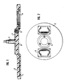
- the handwheel shown separately in FIGS. 1 and 2 from the hatch cover of a combat vehicle consists of a closed disk 8 which has no openings in the axial direction and on the top of which a cam disk 4 is fastened via a screw connection 5, on which the handwheel shaft 3 is also arranged is.
- the closed disc 8 consists of a steel core 1, which is designed as a perforated plate and in the illustrated embodiment consists of two coaxial ring plates which are welded together.
- the steel core 1 is embedded in a radiation protection material 2, for example surrounded by this.
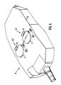
- FIG. 3 shows how the handwheel according to FIGS. 1 and 2 is arranged on a hatch cover of a conventional design for a battle tank shown in FIG. 4.
- the main battle tank itself is partially shown with its turret P, in the upper wall 13 of which two hatches L1 and L2 are arranged.
- FIG. 3 shows the hatch cover 7 covering the hatch L1, which is connected to the outside of the upper wall 13 of the main battle tank via a hinge joint 9.
- the handwheel shaft 3 is seated in a bearing 12.
- the locking linkage 11 moves outward for locking with the upper wall 13.
- the locking linkage 11 is drawn in and the hatch cover 7 can be folded up.
Landscapes
- Engineering & Computer Science (AREA)
- General Engineering & Computer Science (AREA)
- Filling Or Discharging Of Gas Storage Vessels (AREA)
- Aiming, Guidance, Guns With A Light Source, Armor, Camouflage, And Targets (AREA)
Abstract
Description
- Die Erfindung betrifft ein Handrad zur Betätigung des Lukendeckels an einem Kampffahrzeug, insbesondere einem Kampfpanzer.
- Sei der Anbringung von Splitter- oder Strahlenschutzmaterialien im Innenraum eines Kampfpanzers gibt es speziell im Bereich unterhalb der Luken Platzprobleme.
- Die der Erfindung zugrunde liegende Aufgabe bestand darin, im Bereich der Luke eines Kampffahrzeugs, insbesondere eines Kampfpanzers, einen Splitter- und/oder Strahlenschutz derart anzuordnen, daß keine Platzprobleme auftreten.
- Die Losung dieser Aufgabe erfolgt erfindungsgemäß dadurch, daß das Handrad als in axialer Richtung geschlossene Scheibe ausgebildet ist und aus einem als Splitter- und/oder Strahlenschutz geeignetem Material besteht.
- Bei einer besonders vorteilhaften Ausführungsform der Erfindung besitzt die das Handrad bildende Scheibe einen plattenförmigen Stahlkern, der in ein Splitter- und/oder Strahlenschutzmaterial eingebettet ist. Hier bei kann der plattenförmige Stahlkern beispielsweise als Lochblech ausgebildet sein und kann mit Splitter- und/oder Strahlenschutzmaterial umschäumt dein.
- Der Grundgedanke der Erfindung besteht darin, das Handrad selbst als Splitter- und/oder Strahlenschutz auszubilden, was insbesondere dann vorteilhaft ist, wenn das Handrad zentrisch zur Luke angeordnet ist.
- Aus schutztechnischen Gründen sollte dabei das Handrad, das keine Durchbrüche aufweist, möglichst großflächig ausgeführt sein, so daß ein großer Teil der Luke durch diesen zusätzlichen Schutz abgedeckt wird. Die gegebenen Bedienungs- und Funktionsabläufe werden durch das erfindungsgemäße Handrad nicht beeinflußt.
- Im Folgenden wird anhand der beigefügten Zeichnungen ein Ausführungsbeispiel für ein Handrad nach der Erfindung näher erläutert.
- In den Zeichnungen zeigen:
- Fig. 1 einen Axialschnitt durch ein Handrad zur Betätigung eines Lukendeckels;
- Fig. 2 eine Ansicht des Handrades nach Fig. 1 von unten in verkleinerter Darstellung;
- Fig. 3 einen Schnitt nach der Linie A-A in Fig. 4 durch die Oberwand eines Kampfpanzers mit einem an einer Luke angeordneten Handrad nach Fig. 1 und 2;
- Fig. 4 in perspektivischer Darstellung die Teilansicht eines Kampfpanzers mit zwei an seiner Oberwand angeordneten Luken gemäß Fig. 3.
- Das in den Fig. 1 und 2 getrennt vom Lukendeckel eines Kampffahrzeuges dargestellte Handrad besteht aus einer geschlossenen Scheibe 8, die in axialer Richtung keine Durchbrüche aufweist und an deren Oberseite eine Kurvenscheibe 4 über eine Schraubverbindung 5 befestigt ist, an der auch die Handradwelle 3 angeordnet ist.
- Die geschlossene Scheibe 8 besteht aus einem Stahlkern 1, der als Lochblech ausgebildet ist und im dargestellten Ausführungsbeispiel aus zwei koaxial zueinander angeordneten Ringplatten besteht, die miteinander verschweißt sind. Der Stahlkern 1 ist in ein Strahlenschutzmaterial 2 eingebettet, beispielsweise von diesem umschäumt. An der dem Innenraum des Kampffahrzeugs zugewandten Seite sind am Handrad 8 Vertiefungen angeordnet, in denen sich ausklappbare Kastengriffe (6) befinden. Anstelle dieser ausklappbaren Kastengriffe können auch Griffmulden angeordnet sein.
- Fig. 3 zeigt wie das Handrad nach Fig. 1 und 2 an einem Lukendeckel herkömmlicher Bauart für einen in Fig. 4 dargestellten Kampfpanzer angeordnet ist. In Fig. 4 ist der Kampfpanzer selbst teilweise dargestellt mit seinem Turm P, in dessen Oberwand 13 zwei Luken L1 und L2 angeordnet sind. Fig. 3 zeigt den die Luke L1 abdeckenden Lukendeckel 7, der über ein Scharniergelenk 9 mit der Außenseite der Oberwand 13 des Kampfpanzers verbunden ist. Die Handradwelle 3 sitzt in einem Lager 12. in die mit dem Handrad 8 über die Schraubverbindung 5 verbundene Kurvenscheibe 4 greifen Nocken 10 ein, die mit einem Verriegelungsgestänge 11 verbunden sind. Beim Drehen des Handrades 8 in Verriegelungsrichtung bewegt sich das Verriegelungsgestänge 11 nach außen zur Verriegelung mit der Oberwand 13. Beim Drehen in Entriegelungsrichtung wird das Verriegelungsgestänge 11 eingezogen und der Lukendeckel 7 kann hochgeklappt werden.
Claims (7)
Applications Claiming Priority (2)
| Application Number | Priority Date | Filing Date | Title |
|---|---|---|---|
| DE3938588A DE3938588A1 (de) | 1989-11-21 | 1989-11-21 | Handrad zur betaetigung des lukendeckels an einem kampffahrzeug, insbesondere einem kampfpanzer |
| DE3938588 | 1989-11-21 |
Publications (2)
| Publication Number | Publication Date |
|---|---|
| EP0428954A1 true EP0428954A1 (de) | 1991-05-29 |
| EP0428954B1 EP0428954B1 (de) | 1993-06-23 |
Family
ID=6393920
Family Applications (1)
| Application Number | Title | Priority Date | Filing Date |
|---|---|---|---|
| EP90121525A Expired - Lifetime EP0428954B1 (de) | 1989-11-21 | 1990-11-10 | Handrad zur Betätigung des Lukendeckels an einem Kampffahrzeug, insbesondere einem Kampfpanzer |
Country Status (3)
| Country | Link |
|---|---|
| US (1) | US5105718A (de) |
| EP (1) | EP0428954B1 (de) |
| DE (2) | DE3938588A1 (de) |
Families Citing this family (4)
| Publication number | Priority date | Publication date | Assignee | Title |
|---|---|---|---|---|
| USD354721S (en) | 1992-04-02 | 1995-01-24 | Giat Industries | Tank turret |
| US6886447B2 (en) * | 2003-05-30 | 2005-05-03 | United Defense, L.P. | Hatch assembly |
| DE202005000199U1 (de) * | 2005-01-07 | 2006-05-24 | Krauss-Maffei Wegmann Gmbh & Co. Kg | Dichtungsvorrichtung für eine Ein-Ausstiegsluke an einem Kampffahrzeug |
| US9016631B2 (en) * | 2012-04-09 | 2015-04-28 | R4 Integration, Inc. | Multi-purpose hatch system |
Citations (2)
| Publication number | Priority date | Publication date | Assignee | Title |
|---|---|---|---|---|
| US1181289A (en) * | 1915-09-11 | 1916-05-02 | Chrestian Burdahl | Protecting-shield. |
| US1358579A (en) * | 1916-09-12 | 1920-11-09 | Armored Motor Car Company Inc | Armored motor-car |
Family Cites Families (8)
| Publication number | Priority date | Publication date | Assignee | Title |
|---|---|---|---|---|
| DE7823195U1 (de) * | 1978-11-16 | Tank- & Apparatebau, Schwietert & Co Kg, 4720 Beckum | Vorrichtung zum Verschließen einer Ein- und/oder Auslaßöffnung eines Behälters | |
| US2476471A (en) * | 1946-05-31 | 1949-07-19 | Wilson Mfg Company | Escape scuttle |
| US2488796A (en) * | 1946-12-30 | 1949-11-22 | Ludwig S Baier | Scuttle frame and closure unit |
| DE2048205C3 (de) * | 1970-10-01 | 1981-07-02 | Couth Gummiwerke AG, 5000 Köln | Verkleidung-sogenannter Kettenschutz-für Ketten-und Radfahrzeuge |
| CH536480A (de) * | 1970-11-06 | 1973-04-30 | Krauss Maffei Fahrzeug Gmbh | Vorrichtung zum Vermindern der kinetischen Energie von auf eine Wand gerichteten gefährdenden Geschossen |
| US3821935A (en) * | 1973-01-05 | 1974-07-02 | Pullman Transport Leasing Co | Hatch cover |
| US4114424A (en) * | 1976-08-03 | 1978-09-19 | Johnson Andrew P | Gas-fluid-sound isolation door assembly with integral testing means |
| DE3518779A1 (de) * | 1985-05-24 | 1986-12-04 | Clouth Gummiwerke AG, 5000 Köln | Mit einer doppelten panzerung versehener gegenstand |
-
1989
- 1989-11-21 DE DE3938588A patent/DE3938588A1/de not_active Withdrawn
-
1990
- 1990-11-10 DE DE9090121525T patent/DE59001859D1/de not_active Expired - Fee Related
- 1990-11-10 EP EP90121525A patent/EP0428954B1/de not_active Expired - Lifetime
- 1990-11-15 US US07/614,534 patent/US5105718A/en not_active Expired - Lifetime
Patent Citations (2)
| Publication number | Priority date | Publication date | Assignee | Title |
|---|---|---|---|---|
| US1181289A (en) * | 1915-09-11 | 1916-05-02 | Chrestian Burdahl | Protecting-shield. |
| US1358579A (en) * | 1916-09-12 | 1920-11-09 | Armored Motor Car Company Inc | Armored motor-car |
Also Published As
| Publication number | Publication date |
|---|---|
| US5105718A (en) | 1992-04-21 |
| EP0428954B1 (de) | 1993-06-23 |
| DE3938588A1 (de) | 1991-05-23 |
| DE59001859D1 (de) | 1993-07-29 |
Similar Documents
| Publication | Publication Date | Title |
|---|---|---|
| DE69501940T2 (de) | Abnehmbare Befestigung eines Fahrzeugsitzuntergestells auf einem Boden | |
| EP0165268B1 (de) | Behälter, insbesondere für eine förderanlage | |
| DE2138972B2 (de) | Gelenkbeschlag zum Einstellen der Neigung der Rückenlehne von Sitzen, insbesondere Kraftfahrzeugsitzen | |
| DE913012C (de) | Befestigungsvorrichtung, bestehend aus Schraubenbolzen und Mutter | |
| DE10032566A1 (de) | Selbsttätig lösbare Verbindungsbaugruppe, insbesondere zum Verbinden zweier übereinander angeordneter Seefracht-Container | |
| EP1803878A2 (de) | Dekompressionsverschluss | |
| DE3305882A1 (de) | Kampffahrzeug, insbesondere kampfpanzer | |
| EP0540848A1 (de) | Drehringlafette für eine leichte Waffe an einem Kampffahrzeug, insbesondere an einer Luke eines Kampfpanzers | |
| DE69811401T2 (de) | Verschlussvorrichtung für öleinfüllöffnung | |
| EP0428954B1 (de) | Handrad zur Betätigung des Lukendeckels an einem Kampffahrzeug, insbesondere einem Kampfpanzer | |
| EP0367000B1 (de) | Vorrichtung zum Sichern der sichtbaren Schlüsselöffnung bei Schlössern | |
| DE3515820A1 (de) | Lukenabdeckung fuer ein panzerfahrzeug | |
| DE69000647T2 (de) | Scharnier fuer eine abdeckhaube, insbesondere fuer flugzeugtriebwerke. | |
| DE3938584A1 (de) | Gepanzertes kampffahrzeug, insbesondere kampfpanzer | |
| CH678092A5 (de) | ||
| DE3316068C2 (de) | ||
| EP0484642A1 (de) | Dichtungsanordnung zur Verwendung im Einfüllstutzen eines Kraftstofftanks | |
| DE2806491C2 (de) | Verriegelungsanordnung für den Verschluß einer Fahrzeugtür | |
| EP0453626B1 (de) | Mit Schlosseinrichtung versehener versenkbarer Schwenkhebelverschluss | |
| DE20017674U1 (de) | Lösbare mechanische Verriegelungsanordnung zwischen einem schwenkbaren Deckel und einem Behälter, vorzugsweise einem Gepäckfach | |
| DE2038358A1 (de) | Zylinderschloss | |
| DE3142674A1 (de) | "tankcontainer" | |
| EP0863378B1 (de) | Luke für ein gepanzertes Kampffahrzeug | |
| DE3207368C2 (de) | Verschlußdeckel | |
| EP1508768A1 (de) | Deckel für einen im Turm oder der Fahrzeugwanne eines Kampffahrzeugs angeordneten Munitionsraum |
Legal Events
| Date | Code | Title | Description |
|---|---|---|---|
| PUAI | Public reference made under article 153(3) epc to a published international application that has entered the european phase |
Free format text: ORIGINAL CODE: 0009012 |
|
| AK | Designated contracting states |
Kind code of ref document: A1 Designated state(s): CH DE FR GB IT LI |
|
| 17P | Request for examination filed |
Effective date: 19910906 |
|
| 17Q | First examination report despatched |
Effective date: 19921022 |
|
| GRAA | (expected) grant |
Free format text: ORIGINAL CODE: 0009210 |
|
| ITF | It: translation for a ep patent filed | ||
| AK | Designated contracting states |
Kind code of ref document: B1 Designated state(s): CH DE FR GB IT LI |
|
| REF | Corresponds to: |
Ref document number: 59001859 Country of ref document: DE Date of ref document: 19930729 |
|
| ET | Fr: translation filed | ||
| GBT | Gb: translation of ep patent filed (gb section 77(6)(a)/1977) |
Effective date: 19930730 |
|
| PLBE | No opposition filed within time limit |
Free format text: ORIGINAL CODE: 0009261 |
|
| STAA | Information on the status of an ep patent application or granted ep patent |
Free format text: STATUS: NO OPPOSITION FILED WITHIN TIME LIMIT |
|
| 26N | No opposition filed | ||
| PGFP | Annual fee paid to national office [announced via postgrant information from national office to epo] |
Ref country code: GB Payment date: 19991028 Year of fee payment: 10 |
|
| PG25 | Lapsed in a contracting state [announced via postgrant information from national office to epo] |
Ref country code: GB Free format text: LAPSE BECAUSE OF NON-PAYMENT OF DUE FEES Effective date: 20001110 |
|
| GBPC | Gb: european patent ceased through non-payment of renewal fee |
Effective date: 20001110 |
|
| PGFP | Annual fee paid to national office [announced via postgrant information from national office to epo] |
Ref country code: FR Payment date: 20031118 Year of fee payment: 14 |
|
| PGFP | Annual fee paid to national office [announced via postgrant information from national office to epo] |
Ref country code: CH Payment date: 20031121 Year of fee payment: 14 |
|
| PGFP | Annual fee paid to national office [announced via postgrant information from national office to epo] |
Ref country code: DE Payment date: 20031212 Year of fee payment: 14 |
|
| PG25 | Lapsed in a contracting state [announced via postgrant information from national office to epo] |
Ref country code: LI Free format text: LAPSE BECAUSE OF NON-PAYMENT OF DUE FEES Effective date: 20041130 Ref country code: CH Free format text: LAPSE BECAUSE OF NON-PAYMENT OF DUE FEES Effective date: 20041130 |
|
| PG25 | Lapsed in a contracting state [announced via postgrant information from national office to epo] |
Ref country code: DE Free format text: LAPSE BECAUSE OF NON-PAYMENT OF DUE FEES Effective date: 20050601 |
|
| REG | Reference to a national code |
Ref country code: CH Ref legal event code: PL |
|
| PG25 | Lapsed in a contracting state [announced via postgrant information from national office to epo] |
Ref country code: FR Free format text: LAPSE BECAUSE OF NON-PAYMENT OF DUE FEES Effective date: 20050729 |
|
| REG | Reference to a national code |
Ref country code: FR Ref legal event code: ST |
|
| PG25 | Lapsed in a contracting state [announced via postgrant information from national office to epo] |
Ref country code: IT Free format text: LAPSE BECAUSE OF NON-PAYMENT OF DUE FEES;WARNING: LAPSES OF ITALIAN PATENTS WITH EFFECTIVE DATE BEFORE 2007 MAY HAVE OCCURRED AT ANY TIME BEFORE 2007. THE CORRECT EFFECTIVE DATE MAY BE DIFFERENT FROM THE ONE RECORDED. Effective date: 20051110 |