EP0428985B1 - Clou intramédullaire avec pointe en forme de boucle - Google Patents
Clou intramédullaire avec pointe en forme de boucle Download PDFInfo
- Publication number
- EP0428985B1 EP0428985B1 EP90121754A EP90121754A EP0428985B1 EP 0428985 B1 EP0428985 B1 EP 0428985B1 EP 90121754 A EP90121754 A EP 90121754A EP 90121754 A EP90121754 A EP 90121754A EP 0428985 B1 EP0428985 B1 EP 0428985B1
- Authority
- EP
- European Patent Office
- Prior art keywords
- retaining element
- intramedullary nail
- filamentary
- nail
- nail according
- Prior art date
- Legal status (The legal status is an assumption and is not a legal conclusion. Google has not performed a legal analysis and makes no representation as to the accuracy of the status listed.)
- Expired - Lifetime
Links
- 210000000988 bone and bone Anatomy 0.000 claims description 14
- 239000000463 material Substances 0.000 claims description 3
- 230000001954 sterilising effect Effects 0.000 claims description 3
- 238000004659 sterilization and disinfection Methods 0.000 claims description 3
- 238000002788 crimping Methods 0.000 claims description 2
- 230000037431 insertion Effects 0.000 claims 2
- 238000003780 insertion Methods 0.000 claims 2
- 238000000034 method Methods 0.000 description 4
- 239000002184 metal Substances 0.000 description 3
- 229920003002 synthetic resin Polymers 0.000 description 3
- 239000000057 synthetic resin Substances 0.000 description 3
- 238000007373 indentation Methods 0.000 description 2
- 238000003384 imaging method Methods 0.000 description 1
- 230000007246 mechanism Effects 0.000 description 1
- 230000005855 radiation Effects 0.000 description 1
- 230000000717 retained effect Effects 0.000 description 1
- 210000004872 soft tissue Anatomy 0.000 description 1
Images

Classifications
-
- A—HUMAN NECESSITIES
- A61—MEDICAL OR VETERINARY SCIENCE; HYGIENE
- A61B—DIAGNOSIS; SURGERY; IDENTIFICATION
- A61B17/00—Surgical instruments, devices or methods
- A61B17/56—Surgical instruments or methods for treatment of bones or joints; Devices specially adapted therefor
- A61B17/58—Surgical instruments or methods for treatment of bones or joints; Devices specially adapted therefor for osteosynthesis, e.g. bone plates, screws or setting implements
- A61B17/88—Osteosynthesis instruments; Methods or means for implanting or extracting internal or external fixation devices
- A61B17/8861—Apparatus for manipulating flexible wires or straps
-
- A—HUMAN NECESSITIES
- A61—MEDICAL OR VETERINARY SCIENCE; HYGIENE
- A61B—DIAGNOSIS; SURGERY; IDENTIFICATION
- A61B17/00—Surgical instruments, devices or methods
- A61B17/56—Surgical instruments or methods for treatment of bones or joints; Devices specially adapted therefor
- A61B17/58—Surgical instruments or methods for treatment of bones or joints; Devices specially adapted therefor for osteosynthesis, e.g. bone plates, screws or setting implements
- A61B17/68—Internal fixation devices, including fasteners and spinal fixators, even if a part thereof projects from the skin
- A61B17/72—Intramedullary devices, e.g. pins or nails
Definitions
- the invention relates to an intramedullary nail according to the preamble of claim 1.
- intramedullary nails are driven down through the medulla of a fractured bone, usually one of the long bones of the leg.
- the nail is provided with holes through which locking bolts or retaining pins are inserted transverse to the nail and bone to secure the nail in the desired position.
- the locking bolts retain the nail against rotation and longitudinal movement.
- a first locking bolt is inserted through the bone and through a transverse borehole in the nail towards the distal end of the nail.
- One or more additional bolts are then inserted through holes near the proximal end of the nail.
- This procedure is difficult because the transverse locking bolts must meet their respective boreholes precisely, even though these holes are covered by bone and soft tissue.
- the hole at the distal end of the nail is particularly difficult to locate as it is remote from the area of the surgeon's incision.
- sighting mechanisms which use X-ray imaging are employed. This technique is complicated and can lead to a high radiation dosage for the patient and possibly for the surgeon. Meanwhile, if the hole location is incorrectly identified, part of the bone is destroyed unnecessarily.
- an intramedullary nail having a longitudinal slit casing in which a retaining element in the form of a rigid hook is slidably movable.
- the invention provides an intramedullary nail with a looped filamentary retaining element for engaging a transverse locking bolt, and with means for extending and withdrawing the loop of said filamentary retaining element beyond the distal end of the nail easily.
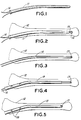
- a device according to the invention in its basic form is shown in Fig. 1.
- a sleeve 11 and a looped filamentary element 14.
- the sleeve may be made out of various materials, for example physiologically acceptable metal or synthetic resin. If a synthetic resin is used it should be capable of heat sterilization.
- the filamentary element is preferably a metal wire or cable again made of a physiologically acceptable metal. In some instances an inert synthetic resin yarn or line may be used. Again the material should be capable of heat sterilization.
- the sleeve is, of course, open at both ends and is flexible enough to follow the contours of the medulla as it is inserted.
- sleeve 11 is inserted into the reamed-out medulla of bone 12 down to the position to which the intramedullary nail is desired to extend.
- the element 14 is already inside the plastic sleeve 11; however it may be inserted after the sleeve 11 is in place.
- the element 14 is pushed down so that it forms loop 16 beyond the distal tip 15 of the sleeve.
- loop 16 may be made as large as desired, so that a transverse locking bolt or retaining pin may be inserted without fine aiming.
- locking bolt 17 is then inserted through loop 16. After the locking bolt 17 is inserted, the element 14 is pulled tight and kept under tension.
- the plastic sleeve 11 may then be removed and, as shown in Fig. 4, an intramedullary nail 13 inserted into the bone 12 around filamentary element 14. Alternatively, the sleeve may be left in place and the nail inserted over or within it.
- the proximal end of the nail may be secured by locking bolts 18 in the conventional way and the ends of the filamentary element are secured under tension to the proximal end of the nail, preferably in the manner described below.
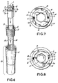
- FIG. 6 A preferred device and method of securing the ends of the filamentary element to the nail is illustrated in Figs. 6, 7 and 8.
- the proximal segment 4 of nail 13 is in the shape of a truncated cone, with the proximal end wider.
- the inner surface of proximal segment 4 is threaded.
- a conical retainer 2 is provided, having its outer surface threaded to engage internal threads of the proximal segment 4 of the nail 13.
- the inside of retainer 2 has straight (i.e., not tapered) sides with opposing longitudinal grooves 5.
- Both ends of filamentary element 14 run inside retainer 2, lying in the grooves 5.
- a locking device 1 is provided to lock the filamentary element in the retainer 2.
- Locking device 1 has a stem 6 and a top 7 with curved sides 7a. Indentations 8 which can accommodate element 14 are formed in the curved sides 7a.
- a hexagonal longitudinal hole 3 is provided through the center of the device.
- retainer 2 is screwed into the socket at the proximal end 4 of nail 13, the ends of filamentary element 14 being removed from the grooves 5 as this occurs.
- the end segments of the filament are placed in grooves 5 and locking device 1 is slid down, the stem 6 thereof sliding into the central hole of the retainer 2 with flanged surface of the top 7 of locking device 1 seated on the rim of the retainer, but inside the nail 13.
- This arrangement is shown in Fig. 7, with the end segments of the filamentary element 14 lodged in the grooves 5 and seated in the indentations 8 of the top of the locking device 1.
- the locking device is then turned clockwise. The stem of the locking device then bears against the end segments of the filamentary element as shown in Fig. 8, forcing them into the grooves 5 and firmly retaining them in their desired positions in nail 13.
- a sleeve is used to position the filamentary element in the medulla before the nail is inserted. It is, however, possible to use a nail specifically designed to be used with a filamentary retaining element and to position the filamentary element in the medulla without the use of an auxiliary sleeve. Such a device is shown in Figs. 9-14.
- an intramedullary nail 13 has the usual elongated tubular casing 13a with an aperture 13b at its distal end. Inside the nail at its distal end is positioned a block 19, shown in detail in Figs. 10 and 11.
- the block 19 has an enlarged head 19a and an extended cylindrical body 19b.
- the body 19b is approximately the same diameter as the internal diameter of nail 13, so that when inserted in the distal end of the nail the shoulders 19c of the head of the block abut the edge or rim of the end of the nail.
- the head 19a of the block has a semi-circular cutout section 19d adapted to receive a transverse locking bolt.
- Grooves 24 for receiving a filamentary retaining element 14 are provided along the sides of block 19.
- a guide cylinder 20 Proximal to the block 19 inside nail 13 is positioned a guide cylinder 20, shown in detail in Figs. 12 and 13. Cylinder 20 in one transverse dimension has the same diameter as the inner diameter of the nail 13. Its sides in the transverse direction have flats 20a.
- Two holes 26 running parallel to the longitudinal axis of the cylinder 20 and extending about half way into the cylinder are provided for receiving the ends of the filamentary element.
- Transverse screw holes 27 for screws 27a are provided for retaining the ends of the filamentary element in the holes 26.
- the cylinder 20 is further provided at its proximal end with a tapped socket 20b which receives the threaded end of a rod 21.
- Nut 22 has a cylindrical body 28 of a diameter approximating that of the interior of nail 13 and an extension 30 which may be given a hexagonal configuration of lesser width.
- the distal end of the nut has a conical entry 31, and a central passage 31a which leads to a tapped section 31b in the hexagonal extension into which rod 21 is threaded.
- the nail is assembled by loading the block 19, cylinder 20 and rod 21 into the nail through, its distal end.
- the block 19 is retained in the nail by crimping the nail to engage the dimple 25 in the side of the block.
- the nut 22 is then slipped over the proximal end of rod 21 and engaged in the threaded extension 30, the hexagonal outer surface of the extension providing operating surfaces for a suitable socket wrench. Crimp 29 in nail 13 prevents nut 22 from moving farther distally within the nail.
- the nail is inserted in the medulla of the bone to be treated in the normal way.
- rod 21 is moved in a distal direction, moving cylinder 20 on rod 21 and also moving filamentary element 14 distally to form a large loop at the distal end of the nail.
- a transverse locking bolt 17 (Fig. 9) may then be inserted through the loop of element 14. The loop is tightened about the bolt by turning the nut extension 30 in the opposite direction. This draws rod 21 in the proximal direction pulling cylinder 20 in the same direction and with it the filamentary element 14.
Landscapes
- Health & Medical Sciences (AREA)
- Orthopedic Medicine & Surgery (AREA)
- Surgery (AREA)
- Life Sciences & Earth Sciences (AREA)
- Heart & Thoracic Surgery (AREA)
- Nuclear Medicine, Radiotherapy & Molecular Imaging (AREA)
- Engineering & Computer Science (AREA)
- Biomedical Technology (AREA)
- Medical Informatics (AREA)
- Molecular Biology (AREA)
- Animal Behavior & Ethology (AREA)
- General Health & Medical Sciences (AREA)
- Public Health (AREA)
- Veterinary Medicine (AREA)
- Neurology (AREA)
- Surgical Instruments (AREA)
Claims (13)
- Clou intramédullaire comportant une extrémité proximale et une extrémité distale, un boîtier et un élément de retenue dans ledit boîtier, ledit élément de retenue s'étendant au-delà d'une extrémité du clou, caractérisé en ce que ledit élément de retenue est un élément filiforme de retenue (14) en bouche pour accrocher un boulon transversal de verrouillage (17), et en ce que ledit clou (13) comporte en outre des moyens (19, 20, 21, 22) pour avancer et retirer la boucle (16) dudit élément filiforme de retenue (14) au-delà de l'extrémité distale (15) du clou (13).
- Clou intramédullaire selon la revendication 1, caractérisé en ce que lesdits moyens comprennent:
un bloc (19) à l'extrémité distale (15) du clou (13), ledit bloc (19) ayant des moyens (24) pour recevoir ledit élément filiforme de retenue (14);
un cylindre de guidage (20) comportant des moyens pour fixer les extrémités de l'élément filiforme de retenue (14);
une tige (21) ayant une extrémité fixée audit cylindre de guidage (20); et
un écrou (22) fixé au clou (13) en position contigue à son extrémité proximale, l'autre extrémité de ladite tige (21) étant vissée à travers ledit écrou (22), de sorte que la rotation dudit écrou (22) déplace axialement ledit cylindre de guidage (20) et ledit élément filiforme de retenue (14) par rapport à ladite tige (21), pour étendre ou tirer la boucle (16) dudit élément filiforme de retenue (14) par rapport à l'extrémité distale (15) du trou (13). - Clou intramédullaire selon la revendication 2, caractérisé en ce que le bloc (19) comporte une tête (19a) adaptée pour engager un boulon de verrouillage (17).
- Clou intramédullaire selon la revendication 2, dans lequel le bloc (19) possède des sillons transversaux (24) adaptés pour recevoir les éléments filiformes de retenue (14).
- Clou intramédullaire selon la revendication 2, dans lequel le bloc (19) présente une découpe (25) pour le retenir dans le clou (13) par sertissage.
- Clou intramédullaire selon la revendication 2, dans lequel les moyens pour retenir les extrémités de l'élément filiforme de retenue (14) comportent des trous (26) s'étendant dans le cylindre de guidage (20) parallèlement à son axe longitudinal, pour recevoir les extrémités de l'élément filiforme de retenue (14), et des moyens (27, 27a) pour fixer les extrémités de l'élément filiforme de retenue (14) dans lesdits trous (26).
- Clou intramédullaire selon la revendication 2, dans lequel l'extrémité proximale du cylindre de guidage (20) comporte une douille taraudée (20b), et l'extrémité distale de la tige (21) est filetée.
- Clou intramédullaire selon la revendication 2, dans lequel ledit écrou (22) comporte:
un corps cylindrique (28);
une saillie (30), de préférence de configuration hexagonale, de diamètre inférieur que celui dudit corps cylindrique (28); et à son extrémité distale une entrée conique (31) adaptée pour recevoir la tige (21). - Clou intramédullaire selon l'une des revendications 1 à 8, caractérisé en ce qu'il comporte en outre:
un cylindre creux de retenue (2) adapté pour être inséré dans l'extrémité proximale (4) du clou intramédullaire (13), autour des segments d' extrémité dudit élément filiforme de retenue (14); et
un dispositif de verrouillage (1) pour insertion dans ledit cylindre de retenue (2), pour ainsi presser les segments d'extrémité de l'élément filiforme de retenue (14) contre l'intérieur du cylindre de retenue (2). - Clou intramédullaire selon la revendication 9, caractérisé en ce que
ledit cylindre de retenue (2) possède des sillons (5) pour recevoir le segment d'extrémité dudit élément filiforme de retenue (14); et le dispositif de verrouillage (1) comporte une manchette rotative (6) pour insertion dans le cylindre de retenue (2), et un sommet (7) pour presser le segment d'extrémité dudit élément filiforme de retenue (14) dans les sillons (5) lorsque ledit manchon (6) est tourné. - Clou intramédullaire selon la revendication 9 ou 10, caractérisé en ce que le sommet (7) du dispositif de verrouillage (1) présente des côtés incurvés (7a).
- Clou intramédullaire selon l'une des revendications 1 à 11, caractérisé en ce qu'il comporte en outre:
une manchette tubulaire allongée (11) adaptée pour être insérée dans le canal médullaire d'un os long (12) et dimensionnée pour s'ajuster dans le clou intramédullaire (13) ou sur celui-ci. - Clou intramédullaire selon la revendication 12, dans lequel ladite manchette (11) est réalisée en un matériau capable d'être stérilisé à la chaleur.
Applications Claiming Priority (2)
| Application Number | Priority Date | Filing Date | Title |
|---|---|---|---|
| US439706 | 1989-11-21 | ||
| US07/439,706 US5034012A (en) | 1989-11-21 | 1989-11-21 | Intramedullary nail with loop tip |
Publications (2)
| Publication Number | Publication Date |
|---|---|
| EP0428985A1 EP0428985A1 (fr) | 1991-05-29 |
| EP0428985B1 true EP0428985B1 (fr) | 1995-03-15 |
Family
ID=23745811
Family Applications (1)
| Application Number | Title | Priority Date | Filing Date |
|---|---|---|---|
| EP90121754A Expired - Lifetime EP0428985B1 (fr) | 1989-11-21 | 1990-11-14 | Clou intramédullaire avec pointe en forme de boucle |
Country Status (5)
| Country | Link |
|---|---|
| US (1) | US5034012A (fr) |
| EP (1) | EP0428985B1 (fr) |
| JP (1) | JPH0640885B2 (fr) |
| CA (1) | CA2009802C (fr) |
| DE (1) | DE69017844T2 (fr) |
Families Citing this family (50)
| Publication number | Priority date | Publication date | Assignee | Title |
|---|---|---|---|---|
| US5281225A (en) * | 1989-06-07 | 1994-01-25 | Guglielmo Vicenzi | Intramedullary pin with self-locking end for metadiaphyseal fractures of long bones |
| US5190549A (en) * | 1990-08-02 | 1993-03-02 | Exactech, Inc. | Locking surgical tool handle system |
| USD341884S (en) | 1992-01-06 | 1993-11-30 | Osteonics Corporation | Alignment rod |
| US5179915A (en) * | 1992-01-06 | 1993-01-19 | Osteonics Corporation | Anatomically matching intramedullary alignment rod |
| US5266075A (en) * | 1992-10-05 | 1993-11-30 | Roy Clark | Tendon threader for endosteal ligament mounting |
| US5429638A (en) * | 1993-02-12 | 1995-07-04 | The Cleveland Clinic Foundation | Bone transport and lengthening system |
| US5626579A (en) * | 1993-02-12 | 1997-05-06 | The Cleveland Clinic Foundation | Bone transport and lengthening system |
| US5350379A (en) * | 1993-02-18 | 1994-09-27 | Genesis Orthopedics | Bone and tissue lengthening device |
| US5536269A (en) * | 1993-02-18 | 1996-07-16 | Genesis Orthopedics | Bone and tissue lengthening device |
| DE69510516T2 (de) * | 1994-10-14 | 1999-11-18 | Synthes Ag Chur, Chur | Osteosynthetisches Gerät zur Befestigung und/oder longitudinalen Ausrichtung |
| US5643273A (en) * | 1995-02-17 | 1997-07-01 | Clark; Ron | ACL bone tunnel projection drill guide and method for its use |
| EP0835080A1 (fr) * | 1995-06-30 | 1998-04-15 | Dominique Persoons | Broche intra-medullaire |
| US5697950A (en) * | 1996-02-07 | 1997-12-16 | Linvatec Corporation | Pre-loaded suture anchor |
| US5707394A (en) * | 1996-02-07 | 1998-01-13 | Bristol-Myers Squibb Company | Pre-loaded suture anchor with rigid extension |
| ATE224675T1 (de) * | 1996-12-02 | 2002-10-15 | Synthes Ag | Flacher marknagel |
| WO2001034045A1 (fr) | 1999-11-11 | 2001-05-17 | Synthes Ag Chur | Clou intramedullaire a expansion radiale |
| US6551321B1 (en) | 2000-06-23 | 2003-04-22 | Centerpulse Orthopedics Inc. | Flexible intramedullary nail |
| KR100393256B1 (ko) * | 2000-06-27 | 2003-07-31 | 박일형 | 골절치료용 골절고정장치 및 그를 이용한 골절고정방법 |
| EP1358852B1 (fr) * | 2002-05-03 | 2005-12-14 | Luciano Trinchese | Appareil pour ostéosynthèse de fragments osseux par clou endomédullaire |
| US7101376B2 (en) * | 2003-04-04 | 2006-09-05 | Elliot Charles Semet | Interlocking IM Nails with threaded guidewire |
| CA2521977A1 (fr) * | 2003-04-10 | 2004-10-21 | Synthes (U.S.A.) | Dispositif pour eclisser temporairement des orteils |
| NZ544958A (en) * | 2003-07-30 | 2009-01-31 | Synthes Gmbh | Surgical nail |
| CN100364484C (zh) * | 2005-02-28 | 2008-01-30 | 刘志成 | 拉丝髓内钉 |
| US9060820B2 (en) | 2005-05-18 | 2015-06-23 | Sonoma Orthopedic Products, Inc. | Segmented intramedullary fracture fixation devices and methods |
| US8961516B2 (en) | 2005-05-18 | 2015-02-24 | Sonoma Orthopedic Products, Inc. | Straight intramedullary fracture fixation devices and methods |
| US7846162B2 (en) | 2005-05-18 | 2010-12-07 | Sonoma Orthopedic Products, Inc. | Minimally invasive actuable bone fixation devices |
| DE102005023069B4 (de) * | 2005-05-19 | 2009-07-09 | Pieske, Oliver, Dr.med. | Implantat zum zugfesten Verbinden zweier Teile eines im Wesentlichen glatt gebrochenen Röhrenknochens |
| US20070173835A1 (en) * | 2006-01-13 | 2007-07-26 | Medoff Robert J | Intramedullary implant for fracture fixation and method of using the same |
| US7931651B2 (en) | 2006-11-17 | 2011-04-26 | Wake Lake University Health Sciences | External fixation assembly and method of use |
| ES2498390T3 (es) * | 2006-11-21 | 2014-09-24 | Oliver Pieske | Implante para huesos tubulares |
| CA2670263A1 (fr) | 2006-11-22 | 2008-05-29 | Sonoma Orthopedic Products, Inc. | Dispositif, outils et procedes de fixation de fracture |
| US8377016B2 (en) | 2007-01-10 | 2013-02-19 | Wake Forest University Health Sciences | Apparatus and method for wound treatment employing periodic sub-atmospheric pressure |
| US20080208171A1 (en) * | 2007-02-23 | 2008-08-28 | Argenta Louis C | Device and method for removing edema |
| EP2299917A1 (fr) | 2008-06-10 | 2011-03-30 | Sonoma Orthopedic Products, Inc. | Dispositif de fixation de fracture, outils et procédés afférents |
| EP2339976B1 (fr) * | 2008-07-09 | 2016-03-16 | Icon Orthopaedic Concepts, LLC | Clou d'arthrodèse de cheville et ensemble stabilisateur |
| US8414584B2 (en) | 2008-07-09 | 2013-04-09 | Icon Orthopaedic Concepts, Llc | Ankle arthrodesis nail and outrigger assembly |
| AU2009296243A1 (en) | 2008-09-26 | 2010-04-01 | Sonoma Orthopedic Products, Inc. | Bone fixation device, tools and methods |
| EP2501312B1 (fr) | 2009-11-16 | 2016-07-20 | The Research Foundation for The State University of New York | Clou intramédullaire préincurvé pour clavicule et procédé pour l'utiliser |
| US20120310283A1 (en) * | 2011-06-02 | 2012-12-06 | Morreale Vittorio M | Segmental spinal fixation system and a method of fixating a plurality of spinal segments |
| EP2814531B1 (fr) * | 2012-02-16 | 2017-02-01 | Synthes GmbH | Pièce rapportée à élution médicamenteuse pour corps implantable |
| ITTO20120687A1 (it) * | 2012-07-31 | 2014-02-01 | Im Ligure S R L Unipersonale | Chiodo intramidollare. |
| WO2014124328A1 (fr) * | 2013-02-08 | 2014-08-14 | Gorsline Robert | Systèmes, procédés et appareils pour la fusion, la stabilisation ou la fixation des os |
| US9041914B2 (en) * | 2013-03-15 | 2015-05-26 | Faro Technologies, Inc. | Three-dimensional coordinate scanner and method of operation |
| EP3016604B1 (fr) * | 2013-07-02 | 2018-10-10 | Cmarr Enterprises | Clou d'arthrodèse tibio-tarsienne incurvé |
| US9770278B2 (en) | 2014-01-17 | 2017-09-26 | Arthrex, Inc. | Dual tip guide wire |
| US9814499B2 (en) | 2014-09-30 | 2017-11-14 | Arthrex, Inc. | Intramedullary fracture fixation devices and methods |
| US10307190B2 (en) * | 2016-04-15 | 2019-06-04 | Arthrex, Inc. | Arthrodesis devices for generating and applying compression within joints |
| US10912652B2 (en) | 2018-07-09 | 2021-02-09 | Arthrex, Inc. | Arthroplasty implant systems for generating and applying dynamic compression |
| EP3838227B1 (fr) * | 2019-12-16 | 2026-02-25 | Waldemar Link GmbH & Co. KG | Tige d'implant de retenue de ciment pour fixation permanente |
| US12137941B2 (en) * | 2021-12-23 | 2024-11-12 | Orthofix S.R.L. | Orthopedic cable bone transport device and bone transport system comprising said device |
Family Cites Families (13)
| Publication number | Priority date | Publication date | Assignee | Title |
|---|---|---|---|---|
| DE532698C (de) * | 1929-07-13 | 1931-09-02 | Moritz Borchardt Dr | Vorrichtung zum Festspannen der fuer die Verfestigung von Knochenbruechen dienenden Draehte |
| US2049361A (en) * | 1934-10-27 | 1936-07-28 | Ericsson Ernst Axel Johan | Wire or ribbon tightening apparatus |
| CH275268A (de) * | 1949-07-13 | 1951-05-15 | Sannmann Alfred | Apparat zum Litzen der Enden eines um einen Gegenstand gebundenen Drahtes. |
| DE1248228B (de) * | 1965-03-24 | 1967-08-24 | Hans Juergen Kaessmann Dr | Vorrichtung zur Behandlung von gebrochenen Roehrenknochen mittels Druckosteosynthese |
| US4409974A (en) * | 1981-06-29 | 1983-10-18 | Freedland Jeffrey A | Bone-fixating surgical implant device |
| EP0070252A1 (fr) * | 1981-07-08 | 1983-01-19 | Ciba-Geigy Ag | Dispositif pour contrôler le remplissage des poches des emballages-perforables par pression |
| DE3347333A1 (de) * | 1982-12-24 | 1984-06-28 | Mecron Medizinische Produkte Gmbh, 1000 Berlin | Kompressionsnagelanordnung |
| US4574795A (en) * | 1982-12-24 | 1986-03-11 | Mecron Medizinische Produkte Gmbh | Compression nail assembly |
| SU1111748A1 (ru) * | 1983-04-08 | 1984-09-07 | Киевский медицинский институт | Устройство дл остеосинтеза трубчатых костей |
| US4557259A (en) * | 1983-08-10 | 1985-12-10 | Henry Ford Hospital | Surgical method and apparatus for inserting wire into the spine |
| US4561432A (en) * | 1983-09-15 | 1985-12-31 | Floyd A. Coard, M.D. | Fractured femur fixation system |
| CH668173A5 (de) * | 1984-05-14 | 1988-12-15 | Synthes Ag | Vorrichtung zum fixieren von roehrenknochenfrakturen mit einem knochenmarknagel und mindestens einem zur verriegelung dienenden querbolzen. |
| GB8721661D0 (en) * | 1987-09-15 | 1987-10-21 | Showell A W Sugicraft Ltd | Spinal/skull fixation device |
-
1989
- 1989-11-21 US US07/439,706 patent/US5034012A/en not_active Expired - Lifetime
-
1990
- 1990-02-12 CA CA002009802A patent/CA2009802C/fr not_active Expired - Lifetime
- 1990-11-14 EP EP90121754A patent/EP0428985B1/fr not_active Expired - Lifetime
- 1990-11-14 DE DE69017844T patent/DE69017844T2/de not_active Expired - Fee Related
- 1990-11-20 JP JP2313013A patent/JPH0640885B2/ja not_active Expired - Lifetime
Also Published As
| Publication number | Publication date |
|---|---|
| JPH0640885B2 (ja) | 1994-06-01 |
| US5034012A (en) | 1991-07-23 |
| DE69017844T2 (de) | 1995-07-27 |
| EP0428985A1 (fr) | 1991-05-29 |
| CA2009802A1 (fr) | 1991-05-21 |
| DE69017844D1 (de) | 1995-04-20 |
| JPH03173555A (ja) | 1991-07-26 |
| CA2009802C (fr) | 1995-08-15 |
Similar Documents
| Publication | Publication Date | Title |
|---|---|---|
| US5034012A (en) | Intramedullary nail with loop tip | |
| KR0176264B1 (ko) | 의료 이식물용 로킹 캡 | |
| US6149654A (en) | Intra-articular drill | |
| US6569165B2 (en) | Modular intramedullary nail | |
| US6648889B2 (en) | Intramedullary hip nail with bifurcated lock | |
| US6406477B1 (en) | Intramedullary nail | |
| US4940467A (en) | Variable length fixation device | |
| US8100911B2 (en) | Fracture fixation apparatus | |
| US6443954B1 (en) | Femoral nail intramedullary system | |
| US5176681A (en) | Intramedullary intertrochanteric fracture fixation appliance and fitting device | |
| US7785326B2 (en) | System for intramedullary rod fixation and method therefor | |
| AU2002309801A1 (en) | Fermoral nail intamedullary system | |
| EP0969774B1 (fr) | Clou centro-medulaire modulaire | |
| CN1219857A (zh) | 供骨折骨缝术用的骨髓腔内钉 | |
| WO1989006940A1 (fr) | Dispositif de fixation a longueur variable | |
| DE20019026U1 (de) | Vorrichtung zur Fixierung eines Implantates | |
| US7060070B1 (en) | Locking nail and aim-taking apparatus | |
| AU5198500A (en) | Inramedullary nail, in particular, intramedullary nail for the tibia | |
| EP1559376A2 (fr) | Dispositif de fixation de moyens de substitution des os | |
| US20260047872A1 (en) | Intramedullary fibula nail with anatomical fit, kit, and method of preparing for and implanting an intramedullary fibula nail | |
| AU2002356834A1 (en) | Intramedullary hip nail with bifurcated lock |
Legal Events
| Date | Code | Title | Description |
|---|---|---|---|
| PUAI | Public reference made under article 153(3) epc to a published international application that has entered the european phase |
Free format text: ORIGINAL CODE: 0009012 |
|
| 17P | Request for examination filed |
Effective date: 19901114 |
|
| AK | Designated contracting states |
Kind code of ref document: A1 Designated state(s): CH DE FR GB LI |
|
| 17Q | First examination report despatched |
Effective date: 19930715 |
|
| GRAA | (expected) grant |
Free format text: ORIGINAL CODE: 0009210 |
|
| AK | Designated contracting states |
Kind code of ref document: B1 Designated state(s): CH DE FR GB LI |
|
| ET | Fr: translation filed | ||
| REF | Corresponds to: |
Ref document number: 69017844 Country of ref document: DE Date of ref document: 19950420 |
|
| PLBE | No opposition filed within time limit |
Free format text: ORIGINAL CODE: 0009261 |
|
| STAA | Information on the status of an ep patent application or granted ep patent |
Free format text: STATUS: NO OPPOSITION FILED WITHIN TIME LIMIT |
|
| 26N | No opposition filed | ||
| REG | Reference to a national code |
Ref country code: GB Ref legal event code: IF02 |
|
| REG | Reference to a national code |
Ref country code: CH Ref legal event code: PUE Owner name: SYNTHES GMBH Free format text: SYNTHES AG CHUR#GRABENSTRASSE 15#7000 CHUR (CH) -TRANSFER TO- SYNTHES GMBH#EIMATTSTRASSE 3#4436 OBERDORF (CH) |
|
| REG | Reference to a national code |
Ref country code: GB Ref legal event code: 732E |
|
| REG | Reference to a national code |
Ref country code: FR Ref legal event code: TP |
|
| PGFP | Annual fee paid to national office [announced via postgrant information from national office to epo] |
Ref country code: CH Payment date: 20081117 Year of fee payment: 19 Ref country code: DE Payment date: 20081107 Year of fee payment: 19 |
|
| PGFP | Annual fee paid to national office [announced via postgrant information from national office to epo] |
Ref country code: FR Payment date: 20081112 Year of fee payment: 19 |
|
| PGFP | Annual fee paid to national office [announced via postgrant information from national office to epo] |
Ref country code: GB Payment date: 20081112 Year of fee payment: 19 |
|
| REG | Reference to a national code |
Ref country code: CH Ref legal event code: PL |
|
| GBPC | Gb: european patent ceased through non-payment of renewal fee |
Effective date: 20091114 |
|
| REG | Reference to a national code |
Ref country code: FR Ref legal event code: ST Effective date: 20100730 |
|
| PG25 | Lapsed in a contracting state [announced via postgrant information from national office to epo] |
Ref country code: CH Free format text: LAPSE BECAUSE OF NON-PAYMENT OF DUE FEES Effective date: 20091130 Ref country code: LI Free format text: LAPSE BECAUSE OF NON-PAYMENT OF DUE FEES Effective date: 20091130 Ref country code: FR Free format text: LAPSE BECAUSE OF NON-PAYMENT OF DUE FEES Effective date: 20091130 |
|
| PG25 | Lapsed in a contracting state [announced via postgrant information from national office to epo] |
Ref country code: DE Free format text: LAPSE BECAUSE OF NON-PAYMENT OF DUE FEES Effective date: 20100601 |
|
| PG25 | Lapsed in a contracting state [announced via postgrant information from national office to epo] |
Ref country code: GB Free format text: LAPSE BECAUSE OF NON-PAYMENT OF DUE FEES Effective date: 20091114 |