EP0429244A2 - Elektrische Strahlungsheizgeräte - Google Patents
Elektrische Strahlungsheizgeräte Download PDFInfo
- Publication number
- EP0429244A2 EP0429244A2 EP90312437A EP90312437A EP0429244A2 EP 0429244 A2 EP0429244 A2 EP 0429244A2 EP 90312437 A EP90312437 A EP 90312437A EP 90312437 A EP90312437 A EP 90312437A EP 0429244 A2 EP0429244 A2 EP 0429244A2
- Authority
- EP
- European Patent Office
- Prior art keywords
- heater
- lamp
- series
- resistance
- resistive
- Prior art date
- Legal status (The legal status is an assumption and is not a legal conclusion. Google has not performed a legal analysis and makes no representation as to the accuracy of the status listed.)
- Granted
Links
Images

Classifications
-
- H—ELECTRICITY
- H05—ELECTRIC TECHNIQUES NOT OTHERWISE PROVIDED FOR
- H05B—ELECTRIC HEATING; ELECTRIC LIGHT SOURCES NOT OTHERWISE PROVIDED FOR; CIRCUIT ARRANGEMENTS FOR ELECTRIC LIGHT SOURCES, IN GENERAL
- H05B3/00—Ohmic-resistance heating
- H05B3/68—Heating arrangements specially adapted for cooking plates or analogous hot-plates
- H05B3/74—Non-metallic plates, e.g. vitroceramic, ceramic or glassceramic hobs, also including power or control circuits
- H05B3/742—Plates having both lamps and resistive heating elements
Definitions
- This invention relates to radiant electric heaters, and in particular to heaters of the kind incorporating an infra-red source such as an infra-red lamp or a molybdenum disilicide filament.
- Radiant electric heaters incorporating infra-red lamps have been described, for example in patent specifications EP 0 117 346 and GB 2 146 431. Such heaters are typically incorporated in cookers and cooktops having a flat, glass ceramic cooking surface.
- the type of lamp used comprises a tungsten filament supported inside a tubular envelope of fused silica, with electrical connections brought out through hermetic pinch seals at the ends of the envelope.
- the lamps are supported in a metal dish, above a layer of thermal insulation material compacted in the dish. It has also been proposed to use bare molybdenum disilicide filaments in place of lamps.
- a radiant electric heater comprising a layer of electrical and thermal insulating material; a wall of electrical and thermal insulating material extending over the insulating material layer; at least one infra-red source means (for example an infra-red lamp) having a relatively high temperature coefficient of resistance; and resistive means arranged to be interposed temporarily in series with said source means upon energization thereof, characterized in that said resistive means is located under said wall.
- infra-red source means for example an infra-red lamp
- the heater may have a single infra-red lamp or other source means, or more than one such source.
- a second resistive means may be connected permanently in series with the source.
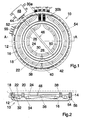
- a radiant electric heater 10 has a container in the form of a metal dish 12 with an upstanding rim 14 and containing a layer of electrical and thermal insulating material 16.
- This material is for example a microporous insulation which comprises a highly-dispersed silica powder, such as silica aerogel or pyrolytic (fumed) silica, mixed with ceramic fibre reinforcement, titanium dioxide opacifier and a small quantity of alumina powder to resist shrinkage, and which is compressed into the dish 12.
- a ring-shaped peripheral wall 18 of ceramic fibre extends around the inside of the rim 14 of the dish 12, on top of the layer 16 and protruding slightly above the edge of the rim 14. When installed in a glass ceramic top cooker the peripheral wall 18 is pressed against the underside of a glass ceramic cooking surface, shown in dashed outline at 20 in Figure 2, the heater 10 being held in position by a spring or other mounting device (not shown).
- two heat sources are provided in the form of tungsten-halogen infra-red lamps 22 and 24, but it should be noted that the invention is equally applicable to heaters with only one such source or with more than two.
- the lamps 22 and 24 are generally circular in configuration and arranged concentrically, and each contains a tungsten filament 26 supported approximately axially on spacers 28 within an infra-red transmissive fused silica envelope 30. These spacers are arranged closely enough together to maintain each filament 26 at the desired distance from its envelope 30 in between each pair of spacers 28 despite the curvature of the envelope 30.
- the filament 26 is secured at each end to connections brought out through flattened hermetic pinch seals at the ends of the envelope 30. These ends are adjacent one another, and the pinch seals extend generally radially of the heater 10 through recesses provided in the underside of the peripheral wall 18 and in the layer 16, and through holes in the rim 14 of the dish 12.
- the surface of the layer 16 is contoured, as shown in Figure 2, to reduce the concentration of heat on the glass ceramic cooking surface 20 immediately above the lamps 22 and 24, and to maintain an adequate thickness for the layer 16.
- the surface of the layer 16 is contoured, as shown in Figure 2, to reduce the concentration of heat on the glass ceramic cooking surface 20 immediately above the lamps 22 and 24, and to maintain an adequate thickness for the layer 16.
- under the lamp 22 there is an annular depression 32, and under the lamp 24 there is another depression 34. Although the presence of these depressions also helps to minimize the overall height of the heater 10, it is considerably broader than is required for this purpose alone.
- the central region 36 of the layer 16, within the lamp 24, is made slightly convex.
- a dividing wall 38 of ceramic fibre is provided between the lamps 22 and 24.
- the inner lamp 24 is intended to be used alone for heating smaller diameter utensils, or together with the outer lamp 22 for heating larger utensils.
- the sections of its envelope 30a and 30b which traverse the annular part of the heater outside the dividing wall 38 are coated with black paint, as are the ends of the lamp 22 outside the rim 14.
- the lamps 22 and 24 are restrained against movement by their ends and by protrusions (for example elongated exhaust tubes) 40 and 42 extending from their envelopes 30.
- the protrusion 40 from the outer lamp 22 is sandwiched between the peripheral wall 18 and the insulating layer 16, and the protrusion 42 from the inner lamp 24 is likewise sandwiched between the dividing wall 38 and the layer 16. Further details of this method of supporting the lamps 22 and 24 are given in patent specifications GB 2 220 333/EP 0 343 868.
- a temperature sensitive rod limiter 44 is provided with its probe 46 extending across the heater 10 from the peripheral wall 18, over the outer 1amp 22 on one side and over the inner lamp 24, as far as the dividing wall 38 on the far side.
- This probe typically comprises a fused silica tube containing a metal rod, which is preferably plated with a reflective material, such as silver, as described in GB 2 146 431.
- a double-pole snap-action switch 48 controlled by the probe 46 has one pole connected in series with the lamps 22 and 24, and a second pole which can be used to control a lamp indicating that the cooking surface 20 is hot.
- the limiter 44 must be calibrated so that it operates to limit the temperature of the glass ceramic cooking surface correctly irrespective of whether only the inner lamp 24 is energized or both lamps 22 and 24 are energized. Accordingly the limiter 44 is made insensitive to the heat in the annular area containing the lamp 22.
- the outer tube of the probe 46 is made in two pieces, a silica section 50 extending over the inner lamp 24 and a metal section 52 extending over the outer annular area of the heater 10. This metal section 52 has a similar coefficient of thermal expansion to the metal rod inside it, so that heat in the annular area of the heater 10 has little or no effect on the operation of the limiter 44.
- the metal section 52 may be plated, for example with silver, in the same way as the metal rod inside the probe 46.
- a coil 54 of electric resistance wire is also provided, extending around the periphery of the heater 10, under the peripheral wall 18 in a groove 56 in the insulation layer 16.
- This coil is made of material having a much lower temperature coefficient of resistance than the filaments 26, for example from an iron-chromium-aluminium alloy.
- the diameter of the coil 54 is typically of the order of 4 to 4.5 mm, and the groove is located with its outer side at least 5 mm from the rim 14 of the dish 12, to maintain electrical isolation.
- the coil 54 has straight sections where it extends past the ends of the lamps 22 and 24, and past the protrusion 40, and its ends are secured to an electrical connector block 55.
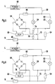
- the resistance wire coil 54 is connected via the limiter 48 between one pole N of an electric supply and one terminal of each of the lamps 22 and 24.
- the second terminal of the inner lamp 24 is coupled to the other pole L of the electric supply via a user-operable switch 58 and a power control unit 60 (such as a cyclic energy regulator).
- the second terminal of the outer lamp 22 is also coupled to the switch 58, but via a second user-operable switch 62 by means of which the user can select whether or not the lamp 22 is energized with the lamp 24.
- a bridge rectifier 64 is coupled via a voltage reducing resistor 66 in parallel with the inner lamp 24, and supplies the actuating coil of a 96V d.c. relay 68 which controls a switch 70 connected in parallel with the resistance wire coil 54.
- the parallel resistance of the lamps 22 and 24 when they are cold (i.e. de-energized) is typically of the order of 2 ohms for an 1800 W heater (e.g. lamps 22 and 24 of 1000W and 800W respectively). However, when they are energized and at their normal operating temperature, their parallel resistance is around 25-30 ohms.
- the resistance of the coil 54 is chosen to be of a similar order of magnitude to the resistance of the lamps at their operating temperature, for example in the range 10 to 30 ohms.
- the coil 54 is in series with the lamp(s) and limits the initial surge of current through the cold lamp filament(s) 26. As the filament 26 in the lamp 24 heats up its resistance rises, so an increasing proportion of the supply voltage is dropped across the lamp 24. Ultimately this voltage reaches a value sufficient to actuate the relay 68, whereupon the switch 70 closes, short-circuiting the coil 54 and applying the full supply voltage directly to the lamp(s).
- the time delay between energization of the lamp(s) and actuation of the relay 68 is a combination of the time delay before the voltage across the lamp(s) is sufficient to actuate the relay 68 and the inherent response time of the relay 68.
- this arrangement provides an appropriate time delay, of at least several tens of milliseconds, without the need for additional timing components. It can be seen from Figure 3 that when the relay 68 is actuated the full supply voltage is applied to the relay circuit and continues to be applied as long as the heater is energized. It is for this reason that a d.c. type is preferred for relay 68, since this has a larger voltage tolerance than an a.c. type.
- the value of the resistance of the coil 54 is selected, in conjunction with the characteristics of the resistor 66 and the relay 68, to provide sufficient limiting of the surge current through the cold lamp filaments without delaying unduly the rise in temperature of the filaments, and if possible to minimize any sudden change in lamp intensity when the relay 68 operates.
- the range of these parameters is chosen to provide the desired operating characteristics when both lamps 22 and 24 are energized (the worst case condition, with maximum surge current). Adjustments within this range may be made to provide acceptable operation when only the lamp 24 is energized.
- the coil 54 dissipates a large power, it does so for such a short time that it is feasible for aesthetic reasons to enclose it between the layer 16 and the peripheral wall 18 without subjecting it to excessive temperatures.
- the invention may also be used, for example, in a heater having only a single infra-red lamp or like heat source, in which case the dividing wall 38 would be omitted.
- the coil 54 may provide the sole limitation of surge current, or it may be used to solve a problem associated in particular with larger, higher power heaters having a surge current limiting resistor permanently in series with the lamp. In such heaters, of the order of 2200 W or more, the current-limiting resistance would need to be of the order of 60-70% of the overall heater resistance in the energized condition in order to conform with regulations on disturbance of electricity supplies. However, if the permanent series resistor is made this size, an unduly high proportion of the power provided by the heater is dissipated in the series resistor.
- Figure 4 shows an arrangement which resolves this problem.
- the single lamp 24 has a resistance 72 connected permanently in series with it.
- This resistance is conveniently disposed on the insulating layer 16, for example within the circular area bounded by the lamp 24.
- the remainder of the circuit is as described with reference to Figure 3, like reference numerals being used to identify like components.
- the resistance 72 has a value providing approximately 40% of the overall heater resistance (that is, lamp 24 plus resistance 72) when the heater is in its energized condition.
- the coil 54 provides the additional resistance needed to limit inrush current when the heater is switched on, but this additional resistance is bypassed by the switch 70 during normal operation to maintain an appropriate proportion of power dissipation in the lamp 24.
- one terminal of the bridge rectifier 64 may be coupled to the mid-point of a pair of resistors 74 and 76 constituting a voltage divider connected in parallel with the resistance wire coil 54 and the relay switch 70.
- resistors 74 and 76 constituting a voltage divider connected in parallel with the resistance wire coil 54 and the relay switch 70.
- bridge rectifier 64 may be connected directly to the limiter switch 48, as shown in Figure 6, and a capacitor 78 connected in parallel with the relay 68 to cooperate with the resistor 66 to provide the required delay in addition to the relay's inherent response time.
Landscapes
- Chemical & Material Sciences (AREA)
- Engineering & Computer Science (AREA)
- Ceramic Engineering (AREA)
- Resistance Heating (AREA)
- Surface Heating Bodies (AREA)
- Electric Stoves And Ranges (AREA)
- Control Of Resistance Heating (AREA)
Applications Claiming Priority (2)
| Application Number | Priority Date | Filing Date | Title |
|---|---|---|---|
| GB898926289A GB8926289D0 (en) | 1989-11-21 | 1989-11-21 | Radiant electric heaters |
| GB8926289 | 1989-11-21 |
Publications (3)
| Publication Number | Publication Date |
|---|---|
| EP0429244A2 true EP0429244A2 (de) | 1991-05-29 |
| EP0429244A3 EP0429244A3 (en) | 1992-03-25 |
| EP0429244B1 EP0429244B1 (de) | 1995-01-25 |
Family
ID=10666658
Family Applications (1)
| Application Number | Title | Priority Date | Filing Date |
|---|---|---|---|
| EP90312437A Expired - Lifetime EP0429244B1 (de) | 1989-11-21 | 1990-11-15 | Elektrische Strahlungsheizgeräte |
Country Status (8)
| Country | Link |
|---|---|
| US (1) | US5049726A (de) |
| EP (1) | EP0429244B1 (de) |
| JP (1) | JPH03176988A (de) |
| AT (1) | ATE117865T1 (de) |
| DE (1) | DE69016363T2 (de) |
| DK (1) | DK0429244T3 (de) |
| ES (1) | ES2066156T3 (de) |
| GB (2) | GB8926289D0 (de) |
Cited By (6)
| Publication number | Priority date | Publication date | Assignee | Title |
|---|---|---|---|---|
| ES2049180A2 (es) * | 1992-09-17 | 1994-04-01 | Eika S Coop Ltda | Mejoras en calefactores radiantes. |
| US5498854A (en) * | 1993-05-21 | 1996-03-12 | Ceramaspeed Limited | Radiant electric heater |
| GB2307385A (en) * | 1995-11-17 | 1997-05-21 | Ceramaspeed Ltd | Radiant heater having resistance heating element with dynamic TCR |
| GB2307384A (en) * | 1995-11-17 | 1997-05-21 | Ceramaspeed Ltd | Damping initial currents using NTC ballast resistance |
| EP0774881A3 (de) * | 1995-11-15 | 1997-12-10 | Ceramaspeed Limited | Infrarot-Heizanordnung |
| EP0969698A1 (de) * | 1998-06-30 | 2000-01-05 | Ceramaspeed Limited | Verfahren zur Herstellung eines elektrischen Heizstrahlers |
Families Citing this family (13)
| Publication number | Priority date | Publication date | Assignee | Title |
|---|---|---|---|---|
| DE4039501A1 (de) * | 1990-12-11 | 1992-06-17 | Ego Elektro Blanc & Fischer | Elektrischer heizkoerper, insbesondere strahlheizkoerper |
| DE4229373A1 (de) * | 1992-09-03 | 1994-03-10 | Ego Elektro Blanc & Fischer | Heizkörper, insbesondere für Kochgeräte |
| GB2280578B (en) * | 1993-07-28 | 1997-02-26 | Ceramaspeed Ltd | Radiant electric heater |
| US5951896A (en) * | 1996-12-04 | 1999-09-14 | Micro C Technologies, Inc. | Rapid thermal processing heater technology and method of use |
| JP2895033B2 (ja) * | 1997-05-12 | 1999-05-24 | 三星電子株式会社 | 電子レンジのインラシュ(inrush)電流防止回路 |
| GB2335834B (en) * | 1998-03-26 | 2002-10-23 | Ceramaspeed Ltd | Radiant electric heater |
| US6310323B1 (en) | 2000-03-24 | 2001-10-30 | Micro C Technologies, Inc. | Water cooled support for lamps and rapid thermal processing chamber |
| JP2004134317A (ja) * | 2002-10-15 | 2004-04-30 | Ushio Inc | 加熱ローラ |
| JP4620164B1 (ja) * | 2009-07-15 | 2011-01-26 | 日本調理機株式会社 | 電気回転釜 |
| FR3043534B1 (fr) * | 2015-11-18 | 2017-12-15 | Jean Michel Senaux | Dispositif et procede de decongelation, rechauffage et/ou cuisson d'un produit alimentaire |
| US10206424B1 (en) * | 2016-09-01 | 2019-02-19 | Mg Heat, Llc | Radiant heating system for vaporizing tobacco and method of use |
| US12059027B2 (en) * | 2016-09-01 | 2024-08-13 | Gunter Gammerler | Consistent two-channel air flow radiant heating system for vaporizing tobacco and method of use |
| US11297875B2 (en) * | 2016-09-01 | 2022-04-12 | Gunter Gammerler | Consistent radiant heating system for vaporizing tobacco and method of use |
Family Cites Families (7)
| Publication number | Priority date | Publication date | Assignee | Title |
|---|---|---|---|---|
| US1799168A (en) * | 1930-02-05 | 1931-04-07 | Johnson Axel | Electric heating unit |
| US2681973A (en) * | 1953-03-05 | 1954-06-22 | Gen Electric | Electric heating appliance |
| FR2301149A1 (fr) * | 1975-02-14 | 1976-09-10 | Dietrich & Cie De | Procede pour la fixation isolante de resistances electriques sur un support calorifuge |
| GB8412339D0 (en) * | 1984-05-15 | 1984-06-20 | Thorn Emi Domestic Appliances | Heating apparatus |
| EP0176027B1 (de) * | 1984-09-22 | 1989-02-01 | E.G.O. Elektro-Geräte Blanc u. Fischer | Strahlheizkörper für Kochgeräte |
| GB8514785D0 (en) * | 1985-06-11 | 1985-07-10 | Micropore International Ltd | Infra-red heaters |
| GB8602507D0 (en) * | 1986-02-01 | 1986-03-05 | Micropore International Ltd | Electric radiation heater |
-
1989
- 1989-11-21 GB GB898926289A patent/GB8926289D0/en active Pending
-
1990
- 1990-11-15 DE DE69016363T patent/DE69016363T2/de not_active Expired - Fee Related
- 1990-11-15 ES ES90312437T patent/ES2066156T3/es not_active Expired - Lifetime
- 1990-11-15 DK DK90312437.8T patent/DK0429244T3/da active
- 1990-11-15 EP EP90312437A patent/EP0429244B1/de not_active Expired - Lifetime
- 1990-11-15 AT AT90312437T patent/ATE117865T1/de not_active IP Right Cessation
- 1990-11-19 GB GB9025093A patent/GB2238450B/en not_active Expired - Fee Related
- 1990-11-20 US US07/616,284 patent/US5049726A/en not_active Expired - Fee Related
- 1990-11-21 JP JP2314502A patent/JPH03176988A/ja active Pending
Cited By (9)
| Publication number | Priority date | Publication date | Assignee | Title |
|---|---|---|---|---|
| ES2049180A2 (es) * | 1992-09-17 | 1994-04-01 | Eika S Coop Ltda | Mejoras en calefactores radiantes. |
| US5498854A (en) * | 1993-05-21 | 1996-03-12 | Ceramaspeed Limited | Radiant electric heater |
| EP0774881A3 (de) * | 1995-11-15 | 1997-12-10 | Ceramaspeed Limited | Infrarot-Heizanordnung |
| US5866879A (en) * | 1995-11-15 | 1999-02-02 | Ceramaspeed Limited | Infra-red heater arrangement |
| GB2307385A (en) * | 1995-11-17 | 1997-05-21 | Ceramaspeed Ltd | Radiant heater having resistance heating element with dynamic TCR |
| GB2307384A (en) * | 1995-11-17 | 1997-05-21 | Ceramaspeed Ltd | Damping initial currents using NTC ballast resistance |
| GB2307384B (en) * | 1995-11-17 | 2000-05-24 | Ceramaspeed Ltd | Infra-red heater |
| GB2307385B (en) * | 1995-11-17 | 2000-05-24 | Ceramaspeed Ltd | Radiant electric heater |
| EP0969698A1 (de) * | 1998-06-30 | 2000-01-05 | Ceramaspeed Limited | Verfahren zur Herstellung eines elektrischen Heizstrahlers |
Also Published As
| Publication number | Publication date |
|---|---|
| ATE117865T1 (de) | 1995-02-15 |
| DE69016363D1 (de) | 1995-03-09 |
| EP0429244A3 (en) | 1992-03-25 |
| GB8926289D0 (en) | 1990-01-10 |
| US5049726A (en) | 1991-09-17 |
| DK0429244T3 (da) | 1995-03-20 |
| GB9025093D0 (en) | 1991-01-02 |
| GB2238450A (en) | 1991-05-29 |
| GB2238450B (en) | 1994-03-23 |
| DE69016363T2 (de) | 1995-05-24 |
| EP0429244B1 (de) | 1995-01-25 |
| ES2066156T3 (es) | 1995-03-01 |
| JPH03176988A (ja) | 1991-07-31 |
Similar Documents
| Publication | Publication Date | Title |
|---|---|---|
| EP0429244B1 (de) | Elektrische Strahlungsheizgeräte | |
| US5043559A (en) | Radiant electric heaters | |
| US5171973A (en) | Radiant electric heaters | |
| CA1266293A (en) | Infra-red heaters | |
| CA1198470A (en) | Electric cooker having temperature warning means | |
| JPS6180788A (ja) | 料理器具用ラジアントヒータ | |
| AU651022B2 (en) | Device for controlling or limiting temperature in an electric cooking appliance | |
| US5908571A (en) | Radiant electric heater arrangement | |
| CA1267927A (en) | Electric radiation heater assemblies | |
| US5004892A (en) | Radiant element | |
| US5892206A (en) | Radiant electric heater arrangement and method of operating the same | |
| US5866879A (en) | Infra-red heater arrangement | |
| EP0892584A2 (de) | Heizvorichtung für Elektroherde | |
| EP0565263A1 (de) | Temperatur kompensierte Steuereinrichtung für elektrische Leistungsregelung | |
| EP0384659A2 (de) | Elektrische Kochplatten | |
| GB2189118A (en) | Heater assembly |
Legal Events
| Date | Code | Title | Description |
|---|---|---|---|
| PUAI | Public reference made under article 153(3) epc to a published international application that has entered the european phase |
Free format text: ORIGINAL CODE: 0009012 |
|
| AK | Designated contracting states |
Kind code of ref document: A2 Designated state(s): AT BE CH DE DK ES FR GB GR IT LI NL SE |
|
| PUAL | Search report despatched |
Free format text: ORIGINAL CODE: 0009013 |
|
| AK | Designated contracting states |
Kind code of ref document: A3 Designated state(s): AT BE CH DE DK ES FR GB GR IT LI NL SE |
|
| 17P | Request for examination filed |
Effective date: 19920910 |
|
| 17Q | First examination report despatched |
Effective date: 19940112 |
|
| GRAA | (expected) grant |
Free format text: ORIGINAL CODE: 0009210 |
|
| AK | Designated contracting states |
Kind code of ref document: B1 Designated state(s): AT BE CH DE DK ES FR GR IT LI NL SE |
|
| REF | Corresponds to: |
Ref document number: 117865 Country of ref document: AT Date of ref document: 19950215 Kind code of ref document: T |
|
| EAL | Se: european patent in force in sweden |
Ref document number: 90312437.8 |
|
| ITF | It: translation for a ep patent filed | ||
| ET | Fr: translation filed | ||
| REG | Reference to a national code |
Ref country code: ES Ref legal event code: FG2A Ref document number: 2066156 Country of ref document: ES Kind code of ref document: T3 |
|
| REF | Corresponds to: |
Ref document number: 69016363 Country of ref document: DE Date of ref document: 19950309 |
|
| REG | Reference to a national code |
Ref country code: DK Ref legal event code: T3 |
|
| REG | Reference to a national code |
Ref country code: GR Ref legal event code: FG4A Free format text: 3014865 |
|
| PLBI | Opposition filed |
Free format text: ORIGINAL CODE: 0009260 |
|
| 26 | Opposition filed |
Opponent name: E.G.O. ELEKTRO-GERAETE BLANC U. FISCHER Effective date: 19951025 |
|
| NLR1 | Nl: opposition has been filed with the epo |
Opponent name: E.G.O. ELEKTRO-GERAETE BLANC U. FISCHER |
|
| PLBF | Reply of patent proprietor to notice(s) of opposition |
Free format text: ORIGINAL CODE: EPIDOS OBSO |
|
| PLBO | Opposition rejected |
Free format text: ORIGINAL CODE: EPIDOS REJO |
|
| PLBN | Opposition rejected |
Free format text: ORIGINAL CODE: 0009273 |
|
| STAA | Information on the status of an ep patent application or granted ep patent |
Free format text: STATUS: OPPOSITION REJECTED |
|
| 27O | Opposition rejected |
Effective date: 19961221 |
|
| NLR2 | Nl: decision of opposition | ||
| PGFP | Annual fee paid to national office [announced via postgrant information from national office to epo] |
Ref country code: GR Payment date: 19971024 Year of fee payment: 8 |
|
| PGFP | Annual fee paid to national office [announced via postgrant information from national office to epo] |
Ref country code: AT Payment date: 19971031 Year of fee payment: 8 |
|
| PGFP | Annual fee paid to national office [announced via postgrant information from national office to epo] |
Ref country code: CH Payment date: 19971103 Year of fee payment: 8 |
|
| PGFP | Annual fee paid to national office [announced via postgrant information from national office to epo] |
Ref country code: SE Payment date: 19971117 Year of fee payment: 8 |
|
| PGFP | Annual fee paid to national office [announced via postgrant information from national office to epo] |
Ref country code: DK Payment date: 19971124 Year of fee payment: 8 |
|
| PG25 | Lapsed in a contracting state [announced via postgrant information from national office to epo] |
Ref country code: AT Free format text: LAPSE BECAUSE OF NON-PAYMENT OF DUE FEES Effective date: 19981115 |
|
| PG25 | Lapsed in a contracting state [announced via postgrant information from national office to epo] |
Ref country code: SE Free format text: LAPSE BECAUSE OF NON-PAYMENT OF DUE FEES Effective date: 19981116 |
|
| PG25 | Lapsed in a contracting state [announced via postgrant information from national office to epo] |
Ref country code: LI Free format text: LAPSE BECAUSE OF NON-PAYMENT OF DUE FEES Effective date: 19981130 Ref country code: GR Free format text: LAPSE BECAUSE OF NON-PAYMENT OF DUE FEES Effective date: 19981130 Ref country code: DK Free format text: LAPSE BECAUSE OF NON-PAYMENT OF DUE FEES Effective date: 19981130 Ref country code: CH Free format text: LAPSE BECAUSE OF NON-PAYMENT OF DUE FEES Effective date: 19981130 |
|
| REG | Reference to a national code |
Ref country code: CH Ref legal event code: PL |
|
| EUG | Se: european patent has lapsed |
Ref document number: 90312437.8 |
|
| PGFP | Annual fee paid to national office [announced via postgrant information from national office to epo] |
Ref country code: BE Payment date: 20011009 Year of fee payment: 12 |
|
| PGFP | Annual fee paid to national office [announced via postgrant information from national office to epo] |
Ref country code: NL Payment date: 20011130 Year of fee payment: 12 |
|
| REG | Reference to a national code |
Ref country code: DK Ref legal event code: EBP |
|
| PGFP | Annual fee paid to national office [announced via postgrant information from national office to epo] |
Ref country code: ES Payment date: 20021008 Year of fee payment: 13 |
|
| PGFP | Annual fee paid to national office [announced via postgrant information from national office to epo] |
Ref country code: FR Payment date: 20021125 Year of fee payment: 13 |
|
| PG25 | Lapsed in a contracting state [announced via postgrant information from national office to epo] |
Ref country code: BE Free format text: LAPSE BECAUSE OF NON-PAYMENT OF DUE FEES Effective date: 20021130 |
|
| PGFP | Annual fee paid to national office [announced via postgrant information from national office to epo] |
Ref country code: DE Payment date: 20030130 Year of fee payment: 13 |
|
| BERE | Be: lapsed |
Owner name: *CERAMASPEED LTD Effective date: 20021130 |
|
| PG25 | Lapsed in a contracting state [announced via postgrant information from national office to epo] |
Ref country code: NL Free format text: LAPSE BECAUSE OF NON-PAYMENT OF DUE FEES Effective date: 20030601 |
|
| NLV4 | Nl: lapsed or anulled due to non-payment of the annual fee |
Effective date: 20030601 |
|
| PG25 | Lapsed in a contracting state [announced via postgrant information from national office to epo] |
Ref country code: ES Free format text: LAPSE BECAUSE OF NON-PAYMENT OF DUE FEES Effective date: 20031117 |
|
| PG25 | Lapsed in a contracting state [announced via postgrant information from national office to epo] |
Ref country code: DE Free format text: LAPSE BECAUSE OF NON-PAYMENT OF DUE FEES Effective date: 20040602 |
|
| PG25 | Lapsed in a contracting state [announced via postgrant information from national office to epo] |
Ref country code: FR Free format text: LAPSE BECAUSE OF NON-PAYMENT OF DUE FEES Effective date: 20040730 |
|
| REG | Reference to a national code |
Ref country code: FR Ref legal event code: ST |
|
| REG | Reference to a national code |
Ref country code: ES Ref legal event code: FD2A Effective date: 20031117 |
|
| PG25 | Lapsed in a contracting state [announced via postgrant information from national office to epo] |
Ref country code: IT Free format text: LAPSE BECAUSE OF NON-PAYMENT OF DUE FEES;WARNING: LAPSES OF ITALIAN PATENTS WITH EFFECTIVE DATE BEFORE 2007 MAY HAVE OCCURRED AT ANY TIME BEFORE 2007. THE CORRECT EFFECTIVE DATE MAY BE DIFFERENT FROM THE ONE RECORDED. Effective date: 20051115 |