EP0429320A2 - Waffe mit Rückstossbremse - Google Patents
Waffe mit RückstossbremseInfo
- Publication number
- EP0429320A2 EP0429320A2 EP90403030.1A EP90403030A EP0429320A2 EP 0429320 A2 EP0429320 A2 EP 0429320A2 EP 90403030 A EP90403030 A EP 90403030A EP 0429320 A2 EP0429320 A2 EP 0429320A2
- Authority
- EP
- European Patent Office
- Prior art keywords
- weapon system
- weapon
- damping device
- deformable
- tubular
- Prior art date
- Legal status (The legal status is an assumption and is not a legal conclusion. Google has not performed a legal analysis and makes no representation as to the accuracy of the status listed.)
- Granted
Links
Images


Definitions
- the present invention relates to a weapon system.
- it finds application to weapon systems for shoulder firing, including but not limited to an anti-tank weapon system. It may also find application in the field of artillery or light infantry weapons.
- the present invention aims to provide a weapon system designed to limit the effort caused by the ejection of a projectile or missile out of a weapon system, whether mortar closed or open.
- the present invention in particular aims to improve the systems described in FR-A-2625800 and FR-A-2644571.
- document FR-A-2644571 describes a weapon system comprising a weapon tube and a fixed reference, the weapon tube being slidably guided with respect to the fixed reference and at least one interposed damping device. between the weapon tube and the fixed reference.
- it is preferably provided several damping stages mounted in cascade.
- each damping stage comprises several damping jacks.
- the Applicant has determined that the damping devices corresponding to the above definition make it possible to limit the force caused by the ejection of a projectile or missile, to reduce the mechanical energy transmitted to the fixed reference and to delay its application much more effectively than a coil spring.
- the damping device may be subject to various variants based for example honeycomb structures spiral rolled webs, mesh structures, cylinders, hollow balls.
- the damping device according to the present invention is preferably designed to transform the force of high amplitude and relatively short duration applied to the weapon tube, during the ejection of a projectile or missile, into a force bearing applied on the fixed reference, of amplitude at most equal to 12 000 N and duration less than 0.2 sec.
- the Applicant has notably conducted extensive experiments on honeycomb structures.
- This pre-blazing honeycomb structures can be operated for example in press, applying on the honeycomb structure a force parallel to the walls of this structure.
- the buckling may correspond to a shrinkage of a few percent of the length of the honeycomb structure, preferably less than 10%, typically less than 5%.
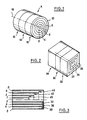
- the damping device A intended to be inserted between a gun tube and a fixed reference, is formed of different deformable elements, tubular, cylindrical of revolution and concentric 2, 4, 6, 8, 10. More specifically, the damping device A is composed of different stages 12, 14, 16 juxtaposed axially, each comprising different concentric tubular deformable elements 2 to 10. According to Figure 1 the different concentric elements 2 to 10 are adjacent.
- the axis 18 should preferably be parallel to the axis of the projectile or missile, in the weapon tube. In the case of a single damper, its axis 18 will be coaxial with the axis of the projectile or missile in the barrel.
- the axis of symmetry is preferably coaxial with the axis of the projectile or missile.
- the device A is designed to transform the mechanical energy of recoil of the weapon tube into heat energy during the ejection of the projectile or missile.
- the embodiment shown in Figure 2 differs from that shown in Figure 1 in that the different elements 22, 24, 26 of each stage 28, 30, 32 are of square section and not cylindrical.
- the number of elements 2 to 10, 22 to 26 in each stage, and the number of stages 12 to 16, 28 to 32 is not limited to the embodiment shown.
- FIG. 3 shows schematically on the lower half-view an embodiment in which the various tubular elements 2 to 10, or 22 to 26, of cylindrical geometry of revolution or square section, are no longer adjacent but separated two by two by an air knife, referenced 34, 36, 38 in Figure 3.
- FIG. 4 shows a variant in which the various elements 2 to 10 or 22 to 26 above are not separated by an air knife but by a sinterable or powdery material 45 such as sand, a resin, a mixture of sand and resin as a binder, or equivalent material.
- a sinterable or powdery material 45 such as sand, a resin, a mixture of sand and resin as a binder, or equivalent material.
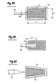
- FIG. 5 shows a variant according to which the elements 2 to 10 or 22 to 24 are, in longitudinal section, a corrugated contour. That is to say that, in longitudinal section, the elements 2 to 10, 22 to 26 are of substantially sinusoidal geometry or equivalent.
- This corrugated wall arrangement applies to the embodiments shown in Figures 1 to 4 above. They also apply to the embodiments shown in Figures 7 to 10 which will be described later.
- FIG. 6 shows an embodiment of the damping device A composed of different stages 46, 48, 50, 52 juxtaposed axially.
- the axis of the device is referenced 54.
- Each stage comprises a unitary structure of the honeycomb type.
- the damping device A comprises a web wound spirally around the axis of the device.
- the damping device A comprises a tubular structure 52 centered on the axis 54 of the device and provided with a plurality of orifices 56 crossing or not oriented radially with respect to the axis 54.
- FIG. 9 differs from that shown in FIG. 8 in that the orifices 56 are of hexagonal section and that they are regularly distributed in order to define a tubular structure of honeycomb type.
- Figure 10 simply illustrates, compared with Figure 9, the possibility of making hexagonal bores 56 of different size.
- the damping device A shown in Figures 11a, 11 is formed of a tubular mesh structure. More specifically, this device is composed of two series of son 58, 60 wound in a spiral, in opposite directions in a tubular envelope centered on the axis 62.
- the pitch of the different windings can be constant. It can vary for the same series of son 58, 60, or from one series to another.
- the different threads 58, 60 have the same section and the two sets of threads wound in different directions comprise the same number of threads.
- FIG. 13 shows a mode of realization of a damping device A comprising on the one hand a deformable honeycomb structure 70 on the other hand a rigid wedge structure 72.
- the deformable honeycomb structure 70 is formed of a body unit defined by a cylindrical outer surface of revolution about the axis 74 and defined by a frustoconical inner surface of revolution about the axis 74 and flared towards the corner 72 to receive it.
- the body 70 is housed in a shell 76.
- the ferrule 76 and the associated body 70 are fixed on the barrel tube, while the wedge 72 is fixed on the fixed reference.
- the ferrule 76 and the associated body 70 are fixed on the fixed reference, while the wedge 72 is fixed on the weapon tube.
- FIG. 14 diagrammatically shows the weapon tube under the reference 78 and the fixed reference under the reference 80.
- it is a long gun whose fixed reference 80 is equipped with means forming a butt 82, handle means 84 and firing control means 86.
- the pistons 87, 91, 93 of the cylinders extend parallel to the axis 98 of the weapon system.
- main cylinder 88 and the auxiliary cylinders 90, 92 given in Figure 14 is schematic.
- these cylinders are annular centered on the axis 98, or there are provided several cylinders equidistant around the axis 98.
- the chamber 104 of the cylinder 100 its volume decreases during the ejection of the missile or projectile M which on the contrary induces the expansion of the expandable structure 106.
- the latter may be formed for example of a balloon-type structure of elastic material.
- the expandable structure 106 rests against, or is integrated in, the deformable structure 108.
- the latter is deformed to transform the mechanical energy of recoil at least partially into heat energy.
- FIG. 17 shows an alternative embodiment of FIG. 15 in which the expandable structure 106 is oriented at rest in a generally radial direction with respect to the axis 98 and is almost completely inserted into the deformable structure 108. It will be noted that on Figures 15 and 17 are shown in phantom the volume that can occupy the expandable structure 106 after expansion.
- damping device can equip one-shot or mufticoup weapon systems.
- the damping device may comprise hollow balls made of aluminum, steel, plastic material, composite material or the like. This variant will now be developed.
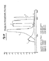
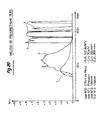
- the measured output velocities of the projectiles were as follows: calibration phase (Fig. 1): 139 m / s, test phases with shock absorber (Fig. 2, 3 and 4): 100 m / s.
- elastomer-based dampers such as the products marketed under the trade names Vibtène and Courbhane and on polyurethane foams, for example in the form of blocks or stacks of washers.
- the Applicant has also made different tests on hollow ball shock absorbers.
- the piston and / or the housing 10 may be tapered, for example tapered, to improve the damping effect by generating a radial component of effort.
- the hollow beads may be manufactured according to any techniques known to those skilled in the art.
- the hollow beads can then be bonded together, using a resin, such as an epoxy resin.
- the diameter of the balls, their thickness, their storage, ordered or loose, the nature of the metal used, the shape of the body containing the balls, the shape of the piston, the nature of the binding resin of the beads may differ from the indications above.
- the beads forming the different layers of the damper may be different in nature or size from one layer to another.
- gun barrel should be understood as encompassing any slidably guided member with respect to the fixed reference. It may be for example a cartridge body or projectile itself.
- the damping device is interposed between the cartridge or the projectile, and the launcher forming a fixed reference of the weapon system.
Applications Claiming Priority (4)
| Application Number | Priority Date | Filing Date | Title |
|---|---|---|---|
| FR8914210A FR2653870B1 (fr) | 1989-10-30 | 1989-10-30 | Systeme d'arme perfectionne muni d'un dispositif d'amortissement. |
| FR8914210 | 1989-10-30 | ||
| FR9010684 | 1990-08-27 | ||
| FR909010684A FR2666142B2 (fr) | 1989-10-30 | 1990-08-27 | Perfectionnements aux sytemes d'arme munis d'un dispositif d'amortissement. |
Publications (4)
| Publication Number | Publication Date |
|---|---|
| EP0429320A1 EP0429320A1 (de) | 1991-05-29 |
| EP0429320A2 true EP0429320A2 (de) | 1991-05-29 |
| EP0429320A3 EP0429320A3 (de) | 1991-11-06 |
| EP0429320B1 EP0429320B1 (de) | 1994-09-07 |
Family
ID=26227627
Family Applications (1)
| Application Number | Title | Priority Date | Filing Date |
|---|---|---|---|
| EP90403030A Expired - Lifetime EP0429320B1 (de) | 1989-10-30 | 1990-10-26 | Waffe mit Rückstossbremse |
Country Status (4)
| Country | Link |
|---|---|
| EP (1) | EP0429320B1 (de) |
| AT (1) | ATE111210T1 (de) |
| DE (1) | DE69012282T2 (de) |
| FR (1) | FR2666142B2 (de) |
Families Citing this family (11)
| Publication number | Priority date | Publication date | Assignee | Title |
|---|---|---|---|---|
| FR2672652B1 (fr) * | 1991-02-12 | 1995-02-03 | Lacroix E Tous Artifices | Systeme d'amortissement notamment pour systemes d'arme. |
| FR2683898B1 (fr) * | 1991-11-20 | 1994-03-04 | Lacroix Tous Artifices Sa | Systeme d'arme perfectionne a amortisseur. |
| FR2720821B1 (fr) * | 1994-06-07 | 1996-08-23 | Serat | Perfectionnements apportés aux systèmes d'arme par régulation de leur balistique interne. |
| US6142055A (en) * | 1998-06-17 | 2000-11-07 | United Defense, L.P. | Matrix gun system |
| US6433203B1 (en) | 1998-11-20 | 2002-08-13 | Basell Technology Company Bv | Bridged metallocenes, preparation, use in catalytic systems |
| SG102669A1 (en) * | 2002-03-13 | 2004-03-26 | Ordnance Dev And Engineering C | Recoil mitigation mechanism |
| US6877774B2 (en) | 2002-05-22 | 2005-04-12 | Hexcel Corporation | Tubular honeycomb articles for use in energy absorption |
| US7527849B2 (en) * | 2004-08-19 | 2009-05-05 | Supracor, Inc. | Honeycomb shock absorber |
| DE102008052074A1 (de) | 2008-10-17 | 2010-04-22 | Rheinmetall Landsysteme Gmbh | Waffensystem mit einem Trägerfahrzeug und einem fahrzeuggebundenen Mörser |
| DE102008056112A1 (de) | 2008-11-06 | 2010-05-12 | Rheinmetall Waffe Munition Gmbh | Mörser |
| DE102008056108A1 (de) | 2008-11-06 | 2010-05-12 | Rheinmetall Waffe Munition Gmbh | Waffe mit Rücklauf und einer diesen dämpfenden Bremseinrichtung |
Family Cites Families (14)
| Publication number | Priority date | Publication date | Assignee | Title |
|---|---|---|---|---|
| DE448652C (de) * | 1926-01-06 | 1927-08-24 | Karl Spiller | Evoluten- oder Spiralfeder, besonders fuer Puffer |
| FR1035971A (fr) * | 1951-04-20 | 1953-09-02 | Nouveau ressort | |
| US3082846A (en) * | 1959-07-01 | 1963-03-26 | Avco Corp | Shock absorbing device |
| US3105411A (en) * | 1961-07-24 | 1963-10-01 | Browning Ind Inc | Recoil absorbing mechanism |
| US3130819A (en) * | 1962-11-09 | 1964-04-28 | Hexcel Products Inc | Energy absorber |
| US3387538A (en) * | 1966-09-19 | 1968-06-11 | Browning Ind Inc | Barrel recoil structure for firearms |
| US3428150A (en) * | 1966-12-28 | 1969-02-18 | Paul M Muspratt | Method and apparatus for gradual absorption of momentum |
| US3501997A (en) * | 1968-03-21 | 1970-03-24 | Us Army | Dynamic force attenuator for a mortar |
| US3552525A (en) * | 1969-02-12 | 1971-01-05 | Hexcel Corp | Energy absorber |
| US3637051A (en) * | 1969-09-15 | 1972-01-25 | T O Paine | Impact energy absorbing system utilizing fracturable material |
| DE2154991C3 (de) * | 1971-11-05 | 1981-04-09 | Volkswagenwerk Ag, 3180 Wolfsburg | Stoßdämpfer |
| DE7243516U (de) * | 1972-11-27 | 1977-06-23 | Adam Opel Ag, 6090 Ruesselsheim | Hohlbauteil, insbesondere für Kraftfahrzeuge |
| US4227593A (en) * | 1976-10-04 | 1980-10-14 | H. H. Robertson Company | Kinetic energy absorbing pad |
| US4672881A (en) * | 1986-07-28 | 1987-06-16 | The United States Of America As Represented By The Secretary Of The Army | Recoilless rocket launcher |
-
1990
- 1990-08-27 FR FR909010684A patent/FR2666142B2/fr not_active Expired - Lifetime
- 1990-10-26 EP EP90403030A patent/EP0429320B1/de not_active Expired - Lifetime
- 1990-10-26 AT AT90403030T patent/ATE111210T1/de not_active IP Right Cessation
- 1990-10-26 DE DE69012282T patent/DE69012282T2/de not_active Expired - Fee Related
Similar Documents
| Publication | Publication Date | Title |
|---|---|---|
| EP0429320A2 (de) | Waffe mit Rückstossbremse | |
| CH650073A5 (fr) | Projectile pour armes de poing et d'epaule et cartouche munie d'un tel projectile. | |
| US20080127850A1 (en) | Bullet with aerodynamic fins and ammunition using same | |
| EP0766807B1 (de) | Persönliches feuerwaffensystem | |
| EP2997310A1 (de) | Flanschlose kartusche | |
| EP0429320B1 (de) | Waffe mit Rückstossbremse | |
| US4172420A (en) | Propellant charge for recoilless weapons | |
| FR2479441A1 (fr) | Magasin pour arme a feu | |
| EP0499526B1 (de) | Dämpfungssystem, insbesondere für Waffensysteme | |
| FR2754566A1 (fr) | Tuyere de moteur-fusee a inserts ejectables | |
| FR2669996A1 (fr) | Projectile pour munitions d'armes a feu de gros calibre. | |
| EP0557209B1 (de) | Stossdämpfende Vorrichtung für Schulterwaffen mit auswechselbarem Wegwerfdämpferelement | |
| FR2653870A1 (fr) | Systeme d'arme perfectionne muni d'un dispositif d'amortissement. | |
| EP0030051A1 (de) | Gewehrgranate | |
| EP0884553B1 (de) | Antriebsgerät für eine die Rückstossenergie begrenzendes Geschoss | |
| US2490101A (en) | Rocket type weapon | |
| FR2648222A1 (fr) | Projectile-fleche a energie cinetique | |
| EP0045226B1 (de) | Mittels Reibung oder heisser Gase zündbarer Verschluss | |
| FR2534681A1 (fr) | Perfectionnements apportes aux systemes d'armes lanceurs de projectiles, notamment aux charges propulsives et a la balistique interieure | |
| BE1003971A3 (fr) | Perfectionnements aux projectiles. | |
| FR2515808A1 (fr) | Piege a balle pour grenade a fusil | |
| EP0331579A1 (de) | Formschlussverbindung zwischen Pfeilgeschoss und Treibkäfig | |
| FR2975769A1 (fr) | Munition avec dispositif de maintien de la charge pyrotechnique de la munition | |
| CH623407A5 (en) | Tubular projectile capable of being fired at a supersonic speed | |
| WO2004079288A1 (fr) | Systeme d’attenuation des vibrations pour canon d’arme a feu, canon ainsi equipe et conforme et arme a feu comportant un tel canon |