EP0430145A1 - Transformateur à champ de fuite magnétique - Google Patents
Transformateur à champ de fuite magnétique Download PDFInfo
- Publication number
- EP0430145A1 EP0430145A1 EP90122565A EP90122565A EP0430145A1 EP 0430145 A1 EP0430145 A1 EP 0430145A1 EP 90122565 A EP90122565 A EP 90122565A EP 90122565 A EP90122565 A EP 90122565A EP 0430145 A1 EP0430145 A1 EP 0430145A1
- Authority
- EP
- European Patent Office
- Prior art keywords
- legs
- pair
- core
- magnetic
- central
- Prior art date
- Legal status (The legal status is an assumption and is not a legal conclusion. Google has not performed a legal analysis and makes no representation as to the accuracy of the status listed.)
- Withdrawn
Links
- 238000004804 winding Methods 0.000 claims abstract description 128
- 230000004907 flux Effects 0.000 claims abstract description 58
- 230000008878 coupling Effects 0.000 claims description 24
- 238000010168 coupling process Methods 0.000 claims description 24
- 238000005859 coupling reaction Methods 0.000 claims description 24
- 229910000859 α-Fe Inorganic materials 0.000 claims description 4
- 239000011248 coating agent Substances 0.000 claims description 3
- 238000000576 coating method Methods 0.000 claims description 3
- 238000009413 insulation Methods 0.000 claims description 2
- 230000005540 biological transmission Effects 0.000 description 7
- 230000007423 decrease Effects 0.000 description 5
- 230000009467 reduction Effects 0.000 description 5
- XEEYBQQBJWHFJM-UHFFFAOYSA-N Iron Chemical compound [Fe] XEEYBQQBJWHFJM-UHFFFAOYSA-N 0.000 description 2
- 239000003990 capacitor Substances 0.000 description 2
- 230000003247 decreasing effect Effects 0.000 description 2
- 239000011347 resin Substances 0.000 description 2
- 229920005989 resin Polymers 0.000 description 2
- 230000004044 response Effects 0.000 description 2
- 239000004677 Nylon Substances 0.000 description 1
- 238000010276 construction Methods 0.000 description 1
- 230000005284 excitation Effects 0.000 description 1
- 239000003365 glass fiber Substances 0.000 description 1
- 229910052742 iron Inorganic materials 0.000 description 1
- 238000010030 laminating Methods 0.000 description 1
- 239000000696 magnetic material Substances 0.000 description 1
- 239000000463 material Substances 0.000 description 1
- 230000004048 modification Effects 0.000 description 1
- 238000012986 modification Methods 0.000 description 1
- 229920001778 nylon Polymers 0.000 description 1
- 230000035699 permeability Effects 0.000 description 1
- 230000005855 radiation Effects 0.000 description 1
- 125000006850 spacer group Chemical group 0.000 description 1
Images

Classifications
-
- H—ELECTRICITY
- H01—ELECTRIC ELEMENTS
- H01F—MAGNETS; INDUCTANCES; TRANSFORMERS; SELECTION OF MATERIALS FOR THEIR MAGNETIC PROPERTIES
- H01F27/00—Details of transformers or inductances, in general
-
- H—ELECTRICITY
- H01—ELECTRIC ELEMENTS
- H01F—MAGNETS; INDUCTANCES; TRANSFORMERS; SELECTION OF MATERIALS FOR THEIR MAGNETIC PROPERTIES
- H01F38/00—Adaptations of transformers or inductances for specific applications or functions
- H01F38/08—High-leakage transformers or inductances
- H01F38/10—Ballasts, e.g. for discharge lamps
Definitions
- the present invention relates to a magnetic leakage transformer.
- a magnetic leakage transformer is used, for example, in a discharge lamp operating device used to operate a discharge lamp such as a fluorescent lamp.
- the magnetic leakage transformer is used in the device not only to generate a high voltage necessary to light a discharge lamp but also to limit a discharge current to be supplied to the discharge lamp as a current-limit inductance while the discharge lamp is operating.
- a choke coil to be used as a current-limit inductance must be associated with the nonmagnetic leakage transformer.
- the construction of the circuit of the discharge lamp operating device is complicated, the number of components of the discharge lamp operating device is increased so that its assembling is complicated, and the entire discharge lamp operating device is increased in size.
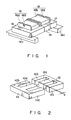
- Fig. 1 schematically shows a conventional magnetic leakage transformer used in a discharge lamp operating device.
- the conventional magnetic leakage transformer has, as shown in Fig. 2, a core unit 14 in which a pair of cores 10, 12 each having E-shaped plane are combined in a state that extending ends of three legs 10a, 10b, 10c and 12a, 12b, 12c are opposed.
- a pair of central legs 10a, 102a of a pair of the cores 10, 12 of the core unit 14 are covered with a primary winding spool 16a and a secondary winding spool 18a, and a primary winding 16b and a secondary winding 18b, both of which are consisted of an insulated wire, are respectively wound on the primary and secondary winding spools 16a and 18a.
- the primary winding spool 16a and the primary winding 16b constitute a primary winding unit 16
- the secondary winding spool 18a and the secondary winding 18b constitute a secondary winding unit 18.
- the primary and secondary winding spools 16a and 18a respectively have supporting bases 16c and 18c extending along the lower surfaces of a pair of the corresponding cores 10 and 12, and the above-described conventional magnetic leakage transformer is mounted at a predetermined position on a circuit board of a discharge lamp operating device through the bases 16c and 18c.
- a pair of side legs 10b and 10c of the three legs 10a, 10b, 10c of one core 10 have the same length, and a pair of side legs of the three legs 12a, 12b, 12c of the other core 12 also have the same length.
- the central legs 10a and 12a are shorter than the pair of side legs 10b, 10c or 12b, 12c disposed at both sides thereof. As shown in Fig.
- a pair of the side legs 10b, 10c and 12b, 12c of a pair of the cores 10, 12 are abutted at their extending ends against each other in a state that the pair of cores 10, 12 are associated with each other as described above, and a magnetic leakage gap "G" is created between the extending ends of the central legs 10a and 12a.
- a magnetic flux directed from the central leg 10a of one core 10 corresponding to the primary winding 16b to the central leg 12a of the other core 12 corresponding to the secondary winding 18b is generated in the core unit 14, and this magnetic flux is passed through a magnetic passage returned to the central leg 10a of the one core 10 through the pair of side legs 12b, 12c of the other core 12 and the pair of side legs 10b, 10c of the one core 10.
- a current having a predetermined relationship to the current supplied to the primary winding 16b is generated in the secondary winding 18b by the magnetic flux.
- a magnetic resistance generated in the magnetic leakage gap "G" between the central legs 10a and 12a of the pair of cores 10 and 12 constitutes a leakage inductance for limiting a discharge current while the discharge lamp connected to the secondary winding 18b is operated.
- the transmission efficiency of magnetic energy to be transmitted from the primary winding 16b to the secondary winding 18b in the above-described conventional magnetic leakage transformer is determined by the interlinkaging number of exciting magnetic fluxes generated by the primary winding 16b to the secondary winding 18b.
- the magnetic leakage gap "G” increases the magnetic resistance.
- the magnetic leakage gap “G” is necessarily indispensable to prevent magnetic saturation of the above-described conventional magnetic leakage transformer in an inverter operation, but the size of the gap “G” required therefor is smaller than that of the gap "G” necessary to obtain the leakage inductance.
- the numbers of turns of the primary and secondary windings 16b and 18b are larger than those in the above described conventional magnetic leakage transformer. Accordingly, the primary and secondary winding units 16 and 18 are large in size, and hence the entire magnetic leakage transformer is large in size and weight.
- the value of the exciting current to be supplied to the primary winding 16b must be increased as compared with that of the nonmagnetic leakage transformer.
- a magnetic leakage transformer comprises: a core unit including a pair of cores each having a central leg, a pair of coupling arms extending from the central leg to both sides thereof, side legs extending in the same direction as the central leg at positions isolated from the central leg at the pair of coupling arms, and magnetic flux leakage legs extending in the same direction as the side legs and the central leg between the side legs and the central leg at the pair of coupling arms in a state isolated therefrom, the pair of cores being disposed in a state that the central legs, two pairs of side legs and two pairs of magnetic flux leakage legs are opposed to each other at their extending ends, and the extending ends of the paired side legs of one core are abutted against those of the paired side legs of the other core, and the paired cores are associated with each other so that magnetic gaps are generated between the extending end of the central leg of the one core and that of the other core and between the extending ends of the paired magnetic flux leakage legs
- a magnetic flux is generated in the pair of central legs of the pair of cores of the core unit when a current is supplied to the first winding unit, thereby circulating the magnetic flux to the above-described central legs through the pair of coupling arms of one core, the pair of side legs, the pair of side legs of the other core, and the pair of coupling arms.
- the pair of central legs are magnetic flux generating portions which are almost irrespective to the magnetic resistance, and the magnetic resistance generated at the abutting portions of the extending ends of the pair of side legs of the one core and those of the other core is extremely small.
- the current generated in the other winding unit by the magnetic flux passing the first magnetic circuit generates magnetic fluxes directed in opposite direction to those in the first magnetic circuit in the one second magnetic circuit composed of the one magnetic flux leakage leg of the one core, one coupling arm, the one side leg, one side leg of the other core, one coupling arm and one magnetic flux leakage leg, and the other magnetic circuit composed of the other magnetic flux leakage leg of the one core, the other coupling arm, the other side leg, the other side leg of the one core, the other coupling arm and the other magnetic flux leakage leg.
- the magnetic gap between the extending ends of the pair of magnetic flux leakage legs of the one core and the extending ends of the pair of magnetic flux leakage legs of the other core of the one and the other second magnetic circuits provides leakage inductance.
- the magnetic gap for providing the leakage inductance is not contained in the first magnetic circuit, magnetic energy transmission efficiency between the first and second winding units is not lowered by the magnetic resistance generated by the magnetic gap.
- the first and second winding units can be reduced in size and weight (and hence the magnetic leakage transformer can be reduced in size and weight), and the input value necessary to obtain a desired output can be reduced as compared with that of the conventional magnetic leakage transformer.
- the second winding unit disposed in the core unit to further surround the first winding unit surrounding the pair of central legs of the pair of cores of the core unit reduces the height of the magnetic leakage transformer and hence decreases the thickness of the magnetic leakage transformer.
- the first winding unit and the second winding unit are coaxially disposed to each other in the same horizontal plane.
- Such arrangement of the first and second winding units further decreases the height of the magnetic leakage transformer and hence further promote the reduction in height of the magnetic leakage transformer.
- the magnetic gaps between the extending ends of the central legs of one core of the core unit and the extending ends of the pair of magnetic flux leakage legs of one core and those of the other core are preferably composed of a space.
- the magnetic gap composed of the space is simply manufactured in comparison with a magnetic gap composed of a spacer of a non-magnetic material, and a magnetic gap composed of a dent formed in a portion of an extending end surface described above and an opening formed in a portion of an extending portion including the extending end surface. Since the magnetic gaps, between the two pairs of magnetic flux leakage legs of the pair of cores, for providing leakage inductance are independent from the magnetic gap, provided between the extending ends of the pair of central legs of the pair of cores, for preventing magnetic saturation, it is easy to adjust the former magnetic gap to obtain a desired leakage inductance.
- the pair of cores of the core unit are made of ferrite.
- the paired cores of ferrite improve the operating efficiency of the magnetic leakage transformer of the present invention.
- the first winding unit and the second winding unit include a first winding and a second winding, respectively, and each of the first and second windings is an insulated wire composed by twisting a plurality of extrafine wires with insulation coating films.
- Such twisted insulated wire decreases the number of turns in each of the first and second windings of the first and second winding units, and improves the degree of heat discharge in the first and second winding units. Therefore, the reduction in size and height of each of the first and second winding units, and hence those of the magnetic leakage transformer of this invention is promoted.
- the magnetic gap between the extending end of the central leg of the one core of the core unit and that of the other core is set smaller than the magnetic gaps between the extending ends of the pair of magnetic flux leakage legs of the one core and those of the other core.
- the former magnetic gap functions to only prevent magnetic saturation in the above-described first magnetic circuit, and the magnetic energy transmission efficiency from the first winding unit to the second winding unit is not disturbed. Since the latter magnetic gaps are irrespective of the first magnetic circuit for preventing the magnetic saturation of the one and the other second magnetic circuits, the latter magnetic gaps can be adjusted to prevent the magnetic saturation in the one and the other second magnetic circuits and to obtain a desired leakage inductance. Therefore, the magnetic leakage transformer of the present invention can function most preferably.
- Fig. 1 is a perspective view schematically showing a conventional magnetic leakage transformer used in a discharge lamp operating device used to operate a discharge lamp such as a fluorescent lamp;
- Fig. 2 is a schematic exploded perspective view of a core unit of the magnetic leakage transformer of Fig. 1;
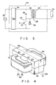
- Fig. 3 is a view schematically showing an electric circuit of a discharge lamp operating device using a magnetic leakage transformer and used to operate a discharge lamp such as a fluorescent lamp;
- Fig. 4 is a schematic perspective view of a magnetic leakage transformer of the present invention instead of the above-described conventional magnetic leakage transformer;
- Fig. 5 is a schematic perspective view of a core unit of the magnetic leakage transformer of Fig. 4.
- Fig. 6 is a schematic cross sectional view taken along a line VI-VI of the magnetic leakage transformer of Fig. 4, illustrating a first magnetic circuit used to transmit magnetic energy from a first winding unit to a second winding unit and a second magnetic circuit including a magnetic gap to obtain a desired leakage inductance.
- Fig. 3 schematically shows an electric circuit of a discharge lamp operating device 20 using a magnetic leakage transformer and used to operate a discharge lamp such as a fluorescent lamp.
- the discharge lamp operating device 20 has a DC power source circuit 24 connected to a commercial AC power source 22, and an inverter circuit 26 connected to the output terminal of the DC power source 24.
- the inverter circuit 26 has a magnetic leakage transformer 28 according to an embodiment of the present invention.
- a discharge lamp 31 such as a fluorescent lamp is connected to a secondary winding 30 of the magnetic leakage transformer 28 and the secondary winding 30 is consisted of an insulated wire.
- One terminal of a primary winding 32 of the magnetic leakage transformer 28 is connected to one terminal of the DC power source 24, and the other terminal of the primary winding 32 is connected to the collector of a switching transistor 34.
- the primary winding 32 is also consisted of the insulated wire.
- a capacitor 36 is connected between the collector of the switching transistor 34 and one terminal of the DC power source 24.
- the emitter of the switching transistor 34 is connected to the other terminal of the DC power source 24, and the base is connected to a control circuit (not shown).
- a diode 38 for protecting the switching transistor 34 is connected between the collector and the emitter of the switching transistor 34.
- Fig. 4 schematically shows an external appearance of the magnetic leakage transformer 28 according to an embodiment of the present invention used in the above-described discharge lamp operating device 20.
- the core unit of this embodiment is composed of a pair of upper and lower cores 40 and 42 made of ferrite.
- Each of cores 40 and 42 has, as shown in Fig. 5, a central leg 40a or 42a, a pair of coupling arms 40b or 42b extending from the central leg 40a or 42a to the both sides thereof, side legs 40c or 42c extending in the same direction as that of the central leg 40a or 42a at positions isolated from the central leg 40a or 42a on the paired coupling arms 40b or 42b, and magnetic flux leakage legs 40d or 42d extending from the paired coupling arms 40b or 42b in the same direction as those of the paired side arms 40c or 42c and the central leg 40a or 42a between the side legs 40c or 42c and the central leg 40a or 42a in the state isolated therefrom.
- the pair of upper and lower cores 40 and 42 are associated in a state that the central legs 40a and 42b, the pair of side legs 40c and 42c, and the pair of magnetic flux leakage legs 40d and 42d are opposed at their extended ends.
- each of the paired side legs 40c and 42c of the paired cores 40 and 42 are longer than that of each of the central legs 40a and 42a, and longer than that of each of the paired magnetic flux leakage legs 40d and 42d.
- the extending length of each of the paired magnetic flux leakage legs 40d and 42d are shorter than that of each of the central legs 40a and 42a.
- each of the pair of magnetic flux legs 40d and 42d are smaller than that of each of the central legs 40a and 42a and each of the pair of side legs 40c and 42c.
- a first winding unit 48 composed of a first annular primary winding spool 46 formed in a square-shaped plane as shown in Fig. 4 and a primary winding 32 wound in a predetermined number of turns on the primary winding spool 46, is inserted into a pair of inner passages 44 formed between the pair of central legs 40a and 42a of the pair of associated upper and lower cores 40 and 42 and two pairs of magnetic flux leakage legs 40d and 42d disposed at both sides of the central legs 40a and 42a.
- the primary winding 32 surrounds the pair of central legs 40a and 42a of the pair of associated upper and lower cores 40 and 42.
- the primary winding spool 46 is formed of heat resistant nonconductive resin such as glass fiber-filled nylon resin to have an angulared C shape cross section (an inverted angulared C shape cross section as seen from a reverse side) as shown in Fig. 6. Both terminals of the primary winding 32 protrude downwardly from a lower horizontal flange of the primary winding spool 46.
- a second winding unit 54 composed of a secondary annular winding spool 52 formed in a square-shaped plane as shown in Fig. 4 and a secondary winding 30 wound in a predetermined number of turns on the secondary winding spool 52, is inserted into a pair of outer passages 40 formed between the two pairs of magnetic leakage legs 40d and 42d of the pair of associated upper and lower cores 40 and 42 and two pairs of side legs 40c and 42c disposed outside the magnetic flux leakage legs 40d and 42d.
- the inner diameter of the second winding unit 54 is larger than the outer diameter of the first winding unit 48 to surround the first winding unit 48.
- the secondary winding spoor 52 has, as shown in Fig. 6, the same cross sectional shape as that of the above-described primary winding spool 46, and is formed of the same material. Both terminals of the secondary winding 30 protrude downwardly from the lower horizontal flange of the secondary winding spool 52.
- an exciting current flows in the primary winding 32 of the first winding unit 48 at each time when the above-described resonance circuit shown in Fig. 3 is resonated.
- the primary winding 32 to which the exciting current is supplied generates an exciting magnetic flux directed toward the pair of coupling arms 40b of one core 40 in the pair of central legs 40a and 42a of the pair of cores 40 and 42 disposed at the center.
- the exciting magnetic flux is circulated to the pair of central legs 40a and 42a through the pair of side legs 40c of the one core 40, the pair of side legs 42c of the other core 42 and the pair of coupling arms 42b of the other core 42 as indicated by a solid line arrow in Fig. 6.
- the pair of central legs 40a and 42a of the pair of cores 40 and 42 are magnetic flux generating portions in the route (first magnetic circuit) of the flow of the exciting magnetic flux indicated by a solid line arrow in Fig. 6, so that the central legs are almost irrespective of the magnetic resistance.
- the only position at which the magnetic resistance is generated in the first magnetic circuit is the extending ends of the two pairs of the side legs 40c and 42c of the pair of cores 40 and 42 and the extending ends are abutted against each other.
- a magnetic resistance generated at the extending ends is extremely small. Therefore, the magnetic energy generated by the excitation of the primary winding 32 is transmitted by substantially 100 % to the secondary winding 30.
- the secondary winding 30 in which magnetic energy is transmitted from the primary winding 32 generates another magnetic flux reverse to the magnetic flux in the above-described first magnetic circuit.
- the another magnetic flux passes, as shown by a broken line arrow in Fig. 6, through one second magnetic circuit passing from one pair of magnetic flux leakage legs 40d and 42d of the pair of cores 40 and 42 through the one coupling arm 42b of the other core 42, one side arm 42C, one side arm 40C of the one core 40, and one coupling arm 40b, and also through the other second magnetic circuit passing from the other pair of magnetic flux leakage legs 40d and 42d through the other coupling arm 42b of the other core 42, the other side arm 42C, the other side arm 40C of the one core 40 and the other coupling arm 40b.
- Magnetic leakage in the gap G2 between the extending ends of the two pairs of magnetic flux leakage legs 40d and 42d of the pair of cores 40 and 42 provides a desired current limiting leakage inductance in one or the other second magnetic circuit to limit the operating current to be discharged from the secondary winding 30 to the discharge lamp 31 (Fig. 3) to a predetermined value or less.
- the gap G2 in the second magnetic circuit is not contained in the above-mentioned first magnetic circuit, the gap G2 does not increase the magnetic resistance of the first magnetic circuit. In other words, the gap G2 does not affect influence to the transmission efficiency of the magnetic energy from the primary winding 32 to the secondary winding 30.
- the second magnetic circuit is shorter in the length of the magnetic path than the first magnetic circuit, an ampere-turn for generating a current limiting leakage inductance can be increased, thereby improving the efficiency of generating the current limiting leakage inductance.
- the magnetic leakage transformer 28, according to one embodiment of the present invention and composed as described above, can reduce in the numbers of turns of the primary windings 32 and the secondary winding 30 required to obtain the same outputs as compared with the conventional magnetic leakage transformer shown in Figs. 1 and 2. As a result, the profiles of the first and second winding units 48 and 52 can be reduced in size and thickness.
- the number of turns of the secondary winding 30 in the magnetic leakage transformer 38 of the one embodiment could be reduced to about 60 % of that of the conventional magnetic leakage transformer, and the entire weight could be decreased to about 80 %.
- the gap G2 of the second magnetic circuit is not included in the above-described first magnetic circuit, and hence the gap G2 does not affect influence to the efficiency of the transmission of the magnetic energy from the primary winding 32 to the secondary winding 32 in the first magnetic circuit. Accordingly, the gap G1 in the first magnetic circuit and the gap G2 in the second magnetic circuit may be independently freely set in response to the operations desired in the corresponding primary and secondary windings 32 and 36.
- the gap G1 is set as narrow as possible so as to reduce the exciting current to be supplied to the primary winding 32 as small as possible while preventing magnetic saturation in the first magnetic circuit, and and the gap G2 can be freely set in a range larger than the gap G1 in response to the magnitude of the load impedance of the discharge lamp 31.
- the first and second winding units 48 and 52 are disposed concentrically in the same plane in the horizontal direction.
- the height H of the magnetic leakage transformer 28 is lower than that of the conventional magnetic leakage transformer. Therefore, the height of the discharge lamp operating device 20 (Fig. 3) using the magnetic leakage transformer 28 of the present invention can be made thinner than that of the discharge lamp operating device 20 using the conventional magnetic leakage transformer. This satisfies a request for reduction in thickness of a lighting equipment in a recent year.
- the inverter circuit 26 used in the magnetic leakage transformer 28 of the present invention is a high frequency inverter circuit which operates with a high frequency of about 20 kHz to about 50 kHz
- the numbers of turns of the primary and secondary windings 32 and 30 of the primary and secondary winding spools 46 and 52 can be reduced by employing an insulated wire, made by twisting a plurality of extrafine wires with insulating coating films, as the primary and secondary windings 32 and 30, and the magnetic leakage transformer 28 of the present invention can be further reduced in size and thickness.
- the reductions in the numbers of turns of the primary and secondary windings 32 and 30 of the primary and secondary winding spools 46 and 52 improve heat radiation degrees in the first and second winding units 48 and 54, and hence further decrease in sizes and thicknesses of the first and second winding units 48 and 54 as well as of the magnetic leakage transformer 28 of the present invention.
- each of a pair of cores 40 and 42 may be composed by laminating thin iron plates of the same planar shape.
- the application of the magnetic leakage transformer 28 of the present invention is not limited to the discharge lamp operating device.
Landscapes
- Engineering & Computer Science (AREA)
- Power Engineering (AREA)
- Coils Of Transformers For General Uses (AREA)
- Regulation Of General Use Transformers (AREA)
- Circuit Arrangements For Discharge Lamps (AREA)
- Coils Or Transformers For Communication (AREA)
Applications Claiming Priority (2)
| Application Number | Priority Date | Filing Date | Title |
|---|---|---|---|
| JP1307331A JPH0670929B2 (ja) | 1989-11-27 | 1989-11-27 | 磁気漏れ変圧器 |
| JP307331/89 | 1989-11-27 |
Publications (1)
| Publication Number | Publication Date |
|---|---|
| EP0430145A1 true EP0430145A1 (fr) | 1991-06-05 |
Family
ID=17967850
Family Applications (1)
| Application Number | Title | Priority Date | Filing Date |
|---|---|---|---|
| EP90122565A Withdrawn EP0430145A1 (fr) | 1989-11-27 | 1990-11-26 | Transformateur à champ de fuite magnétique |
Country Status (4)
| Country | Link |
|---|---|
| US (1) | US5053738A (fr) |
| EP (1) | EP0430145A1 (fr) |
| JP (1) | JPH0670929B2 (fr) |
| KR (1) | KR930000415B1 (fr) |
Cited By (3)
| Publication number | Priority date | Publication date | Assignee | Title |
|---|---|---|---|---|
| US6933821B2 (en) * | 2002-05-31 | 2005-08-23 | Sumida Corporation | Leakage transformer |
| EP3206287A1 (fr) * | 2016-02-15 | 2017-08-16 | Goodrich Control Systems | Unité de redresseur autotransformateur |
| CN112424891A (zh) * | 2018-05-24 | 2021-02-26 | Lg电子株式会社 | 芯、变压器、电力转换装置和包括该电力转换装置的光伏模块 |
Families Citing this family (21)
| Publication number | Priority date | Publication date | Assignee | Title |
|---|---|---|---|---|
| JP4783516B2 (ja) * | 2001-04-26 | 2011-09-28 | スミダコーポレーション株式会社 | インバータトランス |
| JP2002353047A (ja) * | 2001-05-25 | 2002-12-06 | Sumida Corporation | インバータトランス |
| US6873239B2 (en) * | 2002-11-01 | 2005-03-29 | Metglas Inc. | Bulk laminated amorphous metal inductive device |
| TWI298505B (en) * | 2006-01-11 | 2008-07-01 | Delta Electronics Inc | Transformer having auxiliary winding coil for sensing magnetic flux balance and driving circuit using the same |
| JP4279858B2 (ja) * | 2006-07-26 | 2009-06-17 | スミダコーポレーション株式会社 | 磁性素子 |
| US20090237193A1 (en) * | 2008-03-20 | 2009-09-24 | Timothy Craig Wedley | Multi-core inductive device and method of manufacturing |
| JP5081063B2 (ja) * | 2008-05-22 | 2012-11-21 | 本田技研工業株式会社 | 複合型変圧器、および電力変換回路 |
| US8847719B2 (en) * | 2008-07-25 | 2014-09-30 | Cirrus Logic, Inc. | Transformer with split primary winding |
| TW200923985A (en) * | 2008-09-08 | 2009-06-01 | Greatchip Technology Co Ltd | A high-voltage transformer with adjustable flux leakage |
| JP2011082304A (ja) * | 2009-10-06 | 2011-04-21 | Toyota Industries Corp | 複合型リアクトル |
| JP5723590B2 (ja) * | 2010-12-27 | 2015-05-27 | 大電株式会社 | 電源装置 |
| DE102012202578A1 (de) * | 2012-02-20 | 2013-08-22 | Robert Bosch Gmbh | Multiphasenwandler |
| US10840005B2 (en) | 2013-01-25 | 2020-11-17 | Vishay Dale Electronics, Llc | Low profile high current composite transformer |
| US20140265912A1 (en) * | 2013-03-14 | 2014-09-18 | Samsung Electro-Mechanics Co., Ltd. | Coil component and electronic device having the same |
| JP6160142B2 (ja) * | 2013-03-14 | 2017-07-12 | 株式会社リコー | 高電圧インバータ |
| JP6584669B2 (ja) | 2016-07-13 | 2019-10-02 | 三菱電機株式会社 | 漏洩変圧器 |
| JP6635306B2 (ja) * | 2016-09-21 | 2020-01-22 | 株式会社オートネットワーク技術研究所 | リアクトル、及びリアクトル用磁性コア |
| CN111213216B (zh) * | 2017-10-25 | 2023-11-17 | 住友电气工业株式会社 | 线圈组件、电路板以及电源装置 |
| WO2020168101A1 (fr) * | 2019-02-13 | 2020-08-20 | Astronics Advanced Electronic Systems Corp. | Transformateur intégré à faibles pertes de courant alternatif et interface équilibrée d'impédance |
| US11508518B2 (en) * | 2020-02-19 | 2022-11-22 | Tdk Corporation | Coil device with predetermined gap arrangement |
| JP7715614B2 (ja) * | 2021-12-09 | 2025-07-30 | Tdk株式会社 | コイル装置 |
Citations (3)
| Publication number | Priority date | Publication date | Assignee | Title |
|---|---|---|---|---|
| US1777256A (en) * | 1928-07-16 | 1930-09-30 | Jefferson Electric Co | Transformer |
| DE888429C (de) * | 1951-08-01 | 1953-08-31 | Siemens Ag | Zuend- und Betriebseinrichtung fuer elektrische Entladungsroehren, insbesondere Leuchtstofflampen |
| US4613841A (en) * | 1983-11-30 | 1986-09-23 | General Electric Company | Integrated transformer and inductor |
Family Cites Families (2)
| Publication number | Priority date | Publication date | Assignee | Title |
|---|---|---|---|---|
| US2553596A (en) * | 1946-08-16 | 1951-05-22 | Gen Electric | Induction apparatus |
| JP2523560B2 (ja) * | 1986-12-26 | 1996-08-14 | 松下電器産業株式会社 | トランス |
-
1989
- 1989-11-27 JP JP1307331A patent/JPH0670929B2/ja not_active Expired - Fee Related
-
1990
- 1990-11-23 US US07/617,190 patent/US5053738A/en not_active Expired - Fee Related
- 1990-11-26 KR KR1019900019226A patent/KR930000415B1/ko not_active Expired - Fee Related
- 1990-11-26 EP EP90122565A patent/EP0430145A1/fr not_active Withdrawn
Patent Citations (3)
| Publication number | Priority date | Publication date | Assignee | Title |
|---|---|---|---|---|
| US1777256A (en) * | 1928-07-16 | 1930-09-30 | Jefferson Electric Co | Transformer |
| DE888429C (de) * | 1951-08-01 | 1953-08-31 | Siemens Ag | Zuend- und Betriebseinrichtung fuer elektrische Entladungsroehren, insbesondere Leuchtstofflampen |
| US4613841A (en) * | 1983-11-30 | 1986-09-23 | General Electric Company | Integrated transformer and inductor |
Cited By (6)
| Publication number | Priority date | Publication date | Assignee | Title |
|---|---|---|---|---|
| US6933821B2 (en) * | 2002-05-31 | 2005-08-23 | Sumida Corporation | Leakage transformer |
| US7295091B2 (en) | 2002-05-31 | 2007-11-13 | Sumida Corporation | Leakage transformer |
| US7342476B2 (en) | 2002-05-31 | 2008-03-11 | Sumida Corporation | Leakage transformer |
| EP3206287A1 (fr) * | 2016-02-15 | 2017-08-16 | Goodrich Control Systems | Unité de redresseur autotransformateur |
| US10199161B2 (en) | 2016-02-15 | 2019-02-05 | Goodrich Control Systems | Autotransformer rectifier unit |
| CN112424891A (zh) * | 2018-05-24 | 2021-02-26 | Lg电子株式会社 | 芯、变压器、电力转换装置和包括该电力转换装置的光伏模块 |
Also Published As
| Publication number | Publication date |
|---|---|
| JPH03166708A (ja) | 1991-07-18 |
| US5053738A (en) | 1991-10-01 |
| JPH0670929B2 (ja) | 1994-09-07 |
| KR910010547A (ko) | 1991-06-29 |
| KR930000415B1 (ko) | 1993-01-18 |
Similar Documents
| Publication | Publication Date | Title |
|---|---|---|
| US5053738A (en) | Magnetic leakage transformer | |
| US11251713B2 (en) | Multiple parallel-connected resonant converter, inductor-integrated magnetic element and transformer-integrated magnetic element | |
| US4613841A (en) | Integrated transformer and inductor | |
| US4047138A (en) | Power inductor and transformer with low acoustic noise air gap | |
| US6879235B2 (en) | Transformer | |
| KR0139032B1 (ko) | 일체형 emi/rfi 필터 자석 | |
| US4473811A (en) | Single bobbin transformer having multiple delink windings and method of making same | |
| US7446641B2 (en) | Balance transformer | |
| US6937129B2 (en) | Transformer | |
| JPH05299270A (ja) | 電磁装置および電磁コア構造 | |
| JPH01227410A (ja) | 小形トランス | |
| EP0484074A2 (fr) | Transformateur à haute fréquence avec réactance à champ de dispersion fort | |
| US20080284550A1 (en) | Variable Inductor | |
| US4937546A (en) | Ring-core transformer | |
| US4323823A (en) | Unitary ballast structure for operating four fluorescent lamps | |
| JP2591968Y2 (ja) | スイッチング電源トランス | |
| WO1992017892A1 (fr) | Inducteur | |
| JPH0344908A (ja) | 高電圧出力用の小形トランス | |
| JP2000357614A (ja) | チャンバ型トランスおよび該チャンバ型トランスのコイルボビン | |
| JPH0635457Y2 (ja) | コモンモードチョークコイル | |
| KR0123392Y1 (ko) | 권취 컷코어를 사용한 방전관등장치용 안정기 | |
| JP4045582B2 (ja) | インバータトランス | |
| US20010026459A1 (en) | Transformer | |
| JP2003309026A (ja) | インバータトランスおよびこれを用いた放電管点灯回路 | |
| JPH10256060A (ja) | 放電灯用高周波トランス |
Legal Events
| Date | Code | Title | Description |
|---|---|---|---|
| PUAI | Public reference made under article 153(3) epc to a published international application that has entered the european phase |
Free format text: ORIGINAL CODE: 0009012 |
|
| 17P | Request for examination filed |
Effective date: 19901126 |
|
| AK | Designated contracting states |
Kind code of ref document: A1 Designated state(s): BE DE ES FR GB IT NL SE |
|
| 17Q | First examination report despatched |
Effective date: 19920812 |
|
| STAA | Information on the status of an ep patent application or granted ep patent |
Free format text: STATUS: THE APPLICATION IS DEEMED TO BE WITHDRAWN |
|
| 18D | Application deemed to be withdrawn |
Effective date: 19921223 |