EP0430341A2 - Méthode pour le traitement par entrelacement de temps des mots de données et dispositif pour sa mise en oeuvre - Google Patents
Méthode pour le traitement par entrelacement de temps des mots de données et dispositif pour sa mise en oeuvre Download PDFInfo
- Publication number
- EP0430341A2 EP0430341A2 EP90203052A EP90203052A EP0430341A2 EP 0430341 A2 EP0430341 A2 EP 0430341A2 EP 90203052 A EP90203052 A EP 90203052A EP 90203052 A EP90203052 A EP 90203052A EP 0430341 A2 EP0430341 A2 EP 0430341A2
- Authority
- EP
- European Patent Office
- Prior art keywords
- data
- word
- words
- memory
- data words
- Prior art date
- Legal status (The legal status is an assumption and is not a legal conclusion. Google has not performed a legal analysis and makes no representation as to the accuracy of the status listed.)
- Granted
Links
Images
Classifications
-
- H—ELECTRICITY
- H04—ELECTRIC COMMUNICATION TECHNIQUE
- H04J—MULTIPLEX COMMUNICATION
- H04J3/00—Time-division multiplex systems
- H04J3/02—Details
- H04J3/06—Synchronising arrangements
- H04J3/062—Synchronisation of signals having the same nominal but fluctuating bit rates, e.g. using buffers
-
- G—PHYSICS
- G11—INFORMATION STORAGE
- G11B—INFORMATION STORAGE BASED ON RELATIVE MOVEMENT BETWEEN RECORD CARRIER AND TRANSDUCER
- G11B20/00—Signal processing not specific to the method of recording or reproducing; Circuits therefor
Definitions
- the invention relates to a method for time-interleaved processing of a sequence of first data words arriving at a predetermined constant frequency and of second data words arriving at a lower frequency, wherein the processing of each first data word takes less time than the reciprocal of the predetermined frequency, as well as one Arrangement to carry out this procedure.
- Such a method is carried out in particular with signal processors that process digitized samples of analog signal sources as data words or samples of signals that are already digitally available and that are time-dependent, the individual samples of the same signal or the same signal source being processed according to the same program.
- a special application for this is the processing of digitized audio signals, for example from the currently widespread compact disc CD. Since each of these signal values is subjected to the same algorithm in the form of a user program in the signal processor, the number of executable instructions within a sampling period and the scope of the instructions itself is a measure of the performance of the digital signal processor used.
- the sampling period is not completely occupied by instructions from the foreground program. Since the space for the background program is generally limited within the sampling period, the background program must be broken down into a corresponding number of suitable partial programs, such a partial program then being processed in successive sampling periods after each foreground program. At the end of each foreground program there is then a programmed jump to the corresponding sub-program of the background program, and the return to the beginning of the following foreground program is often controlled by a corresponding synchronization signal, so that a waiting loop is provided at the end of a background sub-program in order to respond to this synchronization signal waiting.
- the object of the invention is to provide a method of the type mentioned at the outset, in which the time remaining after the processing of a first data word within the constant sampling period can be used as far as possible for processing at least one further data word.
- This object is achieved according to the invention in that a predetermined first number of the first data words is temporarily stored, and that during a number of directly successive data words, a temporarily stored data word is processed immediately after completion of the processing of the previous data word, as long as after the processing of a data word unprocessed cached data word is present, and that otherwise at least one second data word is processed during a coherent time and then the processing of the first data words is automatically resumed.
- the duration of the coherent time is determined by the number of cached data words and does not have to be fully used, but when the processing of the second data word or all second data words has ended, no waiting cycles have to be inserted, but the next first cached ones can be used immediately Data words are processed again in succession. Since in general only a few second data words, often only a second data word, are to be processed and this processing program generally does not take much time, it is expedient according to one embodiment of the invention that the first number is one and when a new one is stored Data word the previous data word is overwritten and that the duration of the connected time is at most equal to the reciprocal of the predetermined frequency. This duration is practically always sufficient, in particular in the case of audio signal processing, and requires little memory.
- An arrangement for carrying out the method according to the invention with a program-controlled signal processor with a data connection for receiving data words to be processed and for delivering processed data words and with control connections is characterized in that a first memory is provided for the first number of data words, an input of this first Memory is connected to the input for the first data words and writes them into the first memory with a data word clock and an output of this first memory can be connected to the data connection of the signal processor via a first switch controlled by a first read signal from the signal processor, and that an input for the second data words via one of a second read-out signal from the signal processor Controlled second switch can be connected to the data connection of the signal processor.
- an embodiment of the arrangement according to the invention is characterized in that a second memory is provided, an input of this second memory being connectable to the data connection of the signal processor via a third switch controlled by a write-in signal of the signal processor and at an output of the second memory the processed data words can be removed at equal time intervals in accordance with the data word clock.
- This second memory largely corresponds to the first memory, so that overall a symmetrical arrangement is obtained in which the capacity of the second memory corresponds to that of the first memory.
- the capacity of the memory can be selected according to the desired continuous time.
- An expedient embodiment of the arrangement according to the invention for carrying out the embodiment of the method according to the invention is characterized in that at least the first memory (26, 28) only has one data word at a time saves and overwrites the old data word when a new data word is saved. This generally results in a sufficient period of time for processing at least one second data word and requires small memories with very simple control.
- the data words are transmitted in bit series with a data bit clock.
- a further embodiment of the invention is characterized in that the first memory is preceded by a series-parallel converter, which records the data bits one after the other with the data bit clock and, after receiving the data bits of a data word, outputs this data word in parallel to the first memory and from it Data bit clock generates the data word clock.
- the output of the series-parallel converter then represents the source of the parallel data words.
- a second memory is provided, this can be followed by a parallel-series converter, so that the data words are finally emitted bit-serially.
- stereophonic audio signals are generally assumed, the data words being samples of a stereophonic audio signal and each consisting of two data sub-words, with two successive data sub-words each representing corresponding samples of the two stereophonic channels.
- a further embodiment of the arrangement according to the invention is characterized in that at least the first memory consists of two partial memories for one data subword each, whereby the one sub-memory is preceded by a buffer that a first and a second data sub-word clock occurs alternately with every second data sub-word, and that the first buffer stores a data sub-word in the first data sub-word clock and both first sub-memories write in a data sub-word at the second data sub-word clock.
- both data subwords are available in parallel and can be adopted by the signal processor with commands that follow one another immediately.
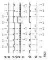
- Line a) uses the arrows to indicate the times at which the first data words arrive, as well as their number, which here relate to a data word arbitrarily designated with n.
- Line b specifies the content of a buffer, which records and buffers the supplied data words. It is assumed that only one data word is temporarily stored here, which is overwritten by the following supplied data word.
- Line c) indicates the time period between the writing of a data word in the buffer and the reading and feeding of this data word, the readout times being indicated by the arrows in line d).
- Line c) also shows the content of a marker memory within the processing arrangement, which is set each time a new first data word is buffered and which is reset for processing when this data word is accepted.
- the distance between two successive readout times is shorter than the distance between the arrival of two successive data words.
- the distance between writing in and reading out the buffer memory for successive data words becomes ever shorter up to data word n.
- the adjacent blocks in row e) are intended to symbolize the processing of a data word, the designation in the blocks indicating the data word that is being processed during this time. It can be seen that at the end of the processing of the data word n the following data word n + 1 has not yet arrived, so that a switch is now made to the processing of a second data word m. For this purpose, a processing time of at most the period of the first data words is available, because if the processing of data word n ends immediately before the arrival of the following data word n + 1, the latter remains in the buffer memory, but only until the arrival of the following data word n + 2, so that it must be read out at least immediately beforehand and transferred to the processing.
- the processed data word is delivered, as can be seen from line f) in FIG. 1. From this it can also be seen that the distances between the processed On the one hand, data words are not constant and, on the other hand, they are also shorter than the time intervals between the incoming first data words. In addition, it is often desirable that the processed data words occur synchronously with the supplied data words, only a constant shift by one or more whole data words is permitted.
- Line h shows the content of this buffer.
- a processed data word is written in at each point in time specified in line f), and the processed first data words temporarily stored on the output side are output in synchronism with the times at which the first data words to be processed arrive, as indicated in line i).
- the signal curve in line g) shows the time interval between reading out the buffer on the output side and the subsequent writing in of the following processed data word and at the same time represents the state of a marker memory on the output side during processing, which is set each time a processed data word is read or output from the buffer and is reset when the next processed data word is written. A new data word can therefore only be written if this signal is high. However, at the end of the processing of the data word n in line e), the signal in line g) is still low, so that the processed data word n cannot yet be output immediately, but this only takes place at the end of the processing block m.
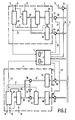
- FIG. 2 shows the block diagram of an arrangement for processing digital stereophonic audio signals which are fed in or out serially and for processing further data words.
- This arrangement essentially comprises an input part 2 for the serial-parallel conversion and temporary storage of data words, a symbolically represented signal processor 3 and an output part 4 with an intermediate memory and a parallel-serial converter. These three parts are connected to one another via a data bus 5 by means of controllable switches 36 and 38 or 56 and 58, and an input 17 for second data words can also be connected to the data bus 5 via a switch 34.
- the data words to be processed are supplied bit-serially via an input 15 together with a bit clock via line 13 and are written into an input shift register 22 serially with this bit clock.
- a predetermined number of consecutive bits (generally 16 bits corresponding to 2 bytes) form a data subword and represent a sample of one of the two audio channels, and two consecutive data subwords represent the related, simultaneous samples of both audio channels.
- a channel control signal on line 11 indicates to which channel the data bits arriving at the same time or the data subwords formed therefrom belong.
- the input 13 for the bit clock signal also leads to an input clock control 20, which also receives the channel control signal via the input 11 and which generates a signal on lines 21 and 23 at the end of each data bit sequence forming a data subword.
- an input clock control 20 which also receives the channel control signal via the input 11 and which generates a signal on lines 21 and 23 at the end of each data bit sequence forming a data subword.
- a signal is generated on line 21, which is fed to an intermediate register 24 and writes the data bits of the first data subword contained in input shift register 22 at the same time in parallel over connection 25.
- both data subwords are transferred to these two input registers 26 and 28. Their content is then available in parallel at the outputs 27 and 29.
- the signal on line 23 is also fed to the signal processor 3 via a control input and sets a marker memory 7 there in order to inform the signal processor 3 that a complete data word consisting of two data sub-words is available in parallel.
- the signal processor 3 As soon as the signal processor 3 has completed the processing of an associated pair of data subwords, it successively supplies the switches 36 and 38 with a readout signal via the lines 37 and 39, as a result of which the switches connect the outputs 27 and 29 to the data bus 5 one after the other that the signal processor can write the two data subwords in immediate succession and feed them to the processing program.
- the signal processor If at the end of the processing of a pair of data sub-words the marker memory 7 is not set (this is the case in FIG. 1 at the end of the processing of the data word n), the signal processor generates a read-out signal on the line 35 which controls the switch 34 and the Input 17 connects to data bus 5, so that a second data word can be taken over and processed in signal processor 3 in parallel via this input 17.
- the signal processor it is also possible to feed a second data word serially to the signal processor 3 via a corresponding separate input, and accordingly a processed second data word can be output in parallel via the data bus 5 or serially via a separate output, which is not shown for the sake of simplicity.
- the signal processor 3 After each processing of a pair of data sub-words, the signal processor 3 outputs these two data sub-words one after the other via the data bus 5 and generates a write-in signal on lines 57 and 59, respectively, which actuate the switches 56 and 58 one after the other, so that the two data sub-words pass through the inputs 53 or 55 can be written into an output register 46 or 48. These are the times specified in line f) in FIG. 1. At the same time, an output marker memory 8 is reset in the signal processor 3.
- a parallel-series converter 42 and an output clock controller 40 are also provided to the write-in signals of the signal processor on lines 57 and 59, bit-by-bit at a data output 19.
- the latter also receives the data bit clock via line 13 and the channel control signal via line 11 and generates internal control signals on lines 41, 43 and 45. This ensures that the data bits of the processed data words at output 19 are synchronized with those at input 15 arriving data bits of the data words to be processed occurs, whereby only a shift by a whole number of data words or pairs of data sub-words has taken place.
- a signal is generated on lines 43 and 45.
- the one data subword is taken from the output register 48 into the output intermediate register 44, and the other data subword is transferred from the output register 46 via a connection 47 and a switch 50, which is just permeable by a corresponding signal on line 41 is switched, and is written via a connection 49 to a parallel input of the output shift register 42 serving as a parallel-series converter with the signal on line 45.
- this parallel data sub-word is emitted bit-serially by the data bit clock at the input 13 serially via the output 19.
- the signal on line 43 also sets the output marker memory 8 in the signal processor 3, because now the output registers 46 and 48 can again each record a data sub-word, since the previous content in the intermediate output register 44 or in the output shift register 42 has been adopted.
- the signal on line 43 thus occurs at the times indicated in FIG. 1, line i).
- a signal is again generated on line 45 and, in addition, the signal on line 41 is switched, so that switch 52 is now switched through the inverter 54 and the second data sub-word from the intermediate output register 44 to the parallel input of the output shift register 42 is fed and written into it by the signal on line 45.
- the second data subword with the data bit clock at input 13 is now output in bit series via output 19.
- the input registers 26 and 28 it is thus possible, when processing regularly arriving data words, to accumulate the time difference between the period of the arrival of these data words and their processing time over successive data words, the arrival of the data words and their processing taking place asynchronously to one another, so that after a number of data words that depend on the time difference mentioned, a coherent period of time is available for processing a second data word.
- the intermediate registers 24 and 44 have only been used because the processing of stereophonic digital audio signals is involved. It is easy to see that a longer processing block for one or more second data words is possible, in particular when using a plurality of input registers corresponding to registers 26 and 28, which would have to be connected in series in the data path and would thus enable the intermediate storage of several data words.
Landscapes
- Engineering & Computer Science (AREA)
- Signal Processing (AREA)
- Computer Hardware Design (AREA)
- Computer Networks & Wireless Communication (AREA)
- Signal Processing For Digital Recording And Reproducing (AREA)
- Time-Division Multiplex Systems (AREA)
Applications Claiming Priority (2)
| Application Number | Priority Date | Filing Date | Title |
|---|---|---|---|
| DE3939072A DE3939072A1 (de) | 1989-11-25 | 1989-11-25 | Verfahren zum zeitverschachtelten verarbeiten von datenwoertern und anordnung zur durchfuehrung dieses verfahrens |
| DE3939072 | 1989-11-25 |
Publications (3)
| Publication Number | Publication Date |
|---|---|
| EP0430341A2 true EP0430341A2 (fr) | 1991-06-05 |
| EP0430341A3 EP0430341A3 (en) | 1992-03-04 |
| EP0430341B1 EP0430341B1 (fr) | 1996-02-07 |
Family
ID=6394211
Family Applications (1)
| Application Number | Title | Priority Date | Filing Date |
|---|---|---|---|
| EP90203052A Expired - Lifetime EP0430341B1 (fr) | 1989-11-25 | 1990-11-19 | Méthode pour le traitement par entrelacement de temps des mots de données et dispositif pour sa mise en oeuvre |
Country Status (4)
| Country | Link |
|---|---|
| US (1) | US5305439A (fr) |
| EP (1) | EP0430341B1 (fr) |
| JP (1) | JP3159702B2 (fr) |
| DE (2) | DE3939072A1 (fr) |
Families Citing this family (2)
| Publication number | Priority date | Publication date | Assignee | Title |
|---|---|---|---|---|
| JP5913910B2 (ja) * | 2011-04-26 | 2016-04-27 | 国際計測器株式会社 | 直動アクチュエータ及び加振装置 |
| TWI489960B (zh) * | 2013-12-25 | 2015-07-01 | Chun Chen Lin | 可攜式馬桶座折疊椅 |
Family Cites Families (10)
| Publication number | Priority date | Publication date | Assignee | Title |
|---|---|---|---|---|
| US4161753A (en) * | 1977-07-08 | 1979-07-17 | International Business Machines Corporation | Video recording disk with interlacing of data for frames on the same track |
| DE3030759A1 (de) * | 1980-08-14 | 1982-03-11 | Licentia Patent-Verwaltungs-Gmbh, 6000 Frankfurt | Schaltung zur zeitfehlerbeseitigung bei der wiedergabe taktbehafteter signale, insbesondere bei einer digitaltonplatte |
| JPH07101482B2 (ja) * | 1982-01-23 | 1995-11-01 | ソニー株式会社 | ディジタル信号記録装置 |
| JPS6052960A (ja) * | 1983-09-01 | 1985-03-26 | Sony Corp | デイスク再生装置 |
| US4651320A (en) * | 1984-12-24 | 1987-03-17 | American Telephone And Telegraph Company | Inband coding of secondary data |
| US4644537A (en) * | 1984-12-24 | 1987-02-17 | American Telephone And Telegraph Company | Inband coding of secondary data |
| US4683567A (en) * | 1985-07-30 | 1987-07-28 | British Columbia Telephone Company | Asynchronous signaling system for digital communication channel |
| US4674087A (en) * | 1985-07-30 | 1987-06-16 | British Columbia Telephone Company | Asynchronous signaling for digital communication channel |
| US4891806A (en) * | 1987-09-18 | 1990-01-02 | Racal Data Communications Inc. | Constellation multiplexed inband secondary channel for voiceband modem |
| US5099478A (en) * | 1989-05-23 | 1992-03-24 | A.T.& T. Paradyne | Communication of secondary channel byte in a synchronous modem without statistical uncertainty |
-
1989
- 1989-11-25 DE DE3939072A patent/DE3939072A1/de not_active Withdrawn
-
1990
- 1990-11-19 DE DE59010118T patent/DE59010118D1/de not_active Expired - Fee Related
- 1990-11-19 EP EP90203052A patent/EP0430341B1/fr not_active Expired - Lifetime
- 1990-11-20 US US07/616,448 patent/US5305439A/en not_active Expired - Lifetime
- 1990-11-26 JP JP31818790A patent/JP3159702B2/ja not_active Expired - Fee Related
Also Published As
| Publication number | Publication date |
|---|---|
| JPH03201733A (ja) | 1991-09-03 |
| DE59010118D1 (de) | 1996-03-21 |
| JP3159702B2 (ja) | 2001-04-23 |
| EP0430341B1 (fr) | 1996-02-07 |
| DE3939072A1 (de) | 1991-05-29 |
| EP0430341A3 (en) | 1992-03-04 |
| US5305439A (en) | 1994-04-19 |
Similar Documents
| Publication | Publication Date | Title |
|---|---|---|
| DE2756890C2 (de) | Schaltungungsanordnung zur Steuerung der Datenübertragung zwischen einer zentralen Verarbeitungseinheit und einer Mehrzahl peripherer Einheiten | |
| DE69025524T2 (de) | Vorrichtung und Verfahren zur Steuerung von Speicherzugriffsanforderungen in einem digitalen Datenverarbeitungssystem | |
| DE3782512T2 (de) | Bearbeiten von zeitkodedaten in einem aufgezeichneten digitalen videosignal. | |
| DE2341549A1 (de) | Einrichtung zur ueberwachung und registrierung von betriebsvorgaengen in einer datenverarbeitungsanlage | |
| DE2432608A1 (de) | Speicheranordnung fuer datenverarbeitungseinrichtungen | |
| EP0218280A2 (fr) | Dispositif de traitement de données | |
| WO1999059055A1 (fr) | Procede de conversion analogique-numerique et dispositif de conversion analogique-numerique correspondant | |
| EP0161034A2 (fr) | Mémoire-tampon pour une ligne d'entrée d'un central téléphonique numérique | |
| DE2217178C3 (de) | Schaltungsanordnung zur Interpolation der Ausgangscodes von PCM-Übertragungssystemen | |
| DE3541759C2 (fr) | ||
| EP0430341B1 (fr) | Méthode pour le traitement par entrelacement de temps des mots de données et dispositif pour sa mise en oeuvre | |
| DE3843372C2 (de) | Verfahren und Schaltungsanordnung zur Taktanpassung in der digitalen Nachrichtentechnik | |
| DE3923872A1 (de) | Schaltungsanordnung zum steuern des zugriffs auf einen speicher | |
| DE4333649A1 (de) | Schnittstelle eines digitalen Signalprozessors | |
| EP0414950B1 (fr) | Méthode de commutation des informations transmises distributivement sur plusieurs tranches de temps | |
| DE19843704A1 (de) | Vorrichtung und Verfahren zur Digitalaufzeichnung und -wiedergabe | |
| DE4039889C2 (de) | Digitalsignal-Verarbeitungsvorrichtung zur arithmetischen Verarbeitung eines digitalen Eingangs-Audiosignals und ihre Verwendung | |
| DE69301835T2 (de) | Mehrkomponenten X-Paketkodierer und Dekodierer dafür | |
| DE2657243A1 (de) | Schaltungsanordnung zur uebermittlung von signalisierungsvorgaengen | |
| DE2641488B1 (de) | Schaltungsanordnung zum Phasenausgleich bei PCM-Vermittlungsstellen | |
| DE3132984C2 (fr) | ||
| DE2732068A1 (de) | Schaltungsanordnung zur steuerung des informationsaustauschs zwischen den peripheren einrichtungen und der zentralen steuereinrichtung einer fernmelde-, insbesondere fernsprechvermittlungsanlage | |
| DE2849382C2 (de) | Adressiervorrichtung für eine elektrische Recheneinrichtung | |
| DE4407948C2 (de) | Schnittstelle | |
| DE69617633T2 (de) | Verfahren und einrichtung zum auslesen von datenblöcken für eine anzahl von benutzergruppen |
Legal Events
| Date | Code | Title | Description |
|---|---|---|---|
| PUAI | Public reference made under article 153(3) epc to a published international application that has entered the european phase |
Free format text: ORIGINAL CODE: 0009012 |
|
| AK | Designated contracting states |
Kind code of ref document: A2 Designated state(s): DE FR GB IT |
|
| PUAL | Search report despatched |
Free format text: ORIGINAL CODE: 0009013 |
|
| AK | Designated contracting states |
Kind code of ref document: A3 Designated state(s): DE FR GB IT |
|
| 17P | Request for examination filed |
Effective date: 19920727 |
|
| 17Q | First examination report despatched |
Effective date: 19940406 |
|
| GRAA | (expected) grant |
Free format text: ORIGINAL CODE: 0009210 |
|
| AK | Designated contracting states |
Kind code of ref document: B1 Designated state(s): DE FR GB IT |
|
| REF | Corresponds to: |
Ref document number: 59010118 Country of ref document: DE Date of ref document: 19960321 |
|
| ITF | It: translation for a ep patent filed | ||
| GBT | Gb: translation of ep patent filed (gb section 77(6)(a)/1977) |
Effective date: 19960424 |
|
| ET | Fr: translation filed | ||
| PLBE | No opposition filed within time limit |
Free format text: ORIGINAL CODE: 0009261 |
|
| STAA | Information on the status of an ep patent application or granted ep patent |
Free format text: STATUS: NO OPPOSITION FILED WITHIN TIME LIMIT |
|
| 26N | No opposition filed | ||
| REG | Reference to a national code |
Ref country code: FR Ref legal event code: CD |
|
| REG | Reference to a national code |
Ref country code: GB Ref legal event code: IF02 |
|
| PGFP | Annual fee paid to national office [announced via postgrant information from national office to epo] |
Ref country code: FR Payment date: 20041125 Year of fee payment: 15 |
|
| PGFP | Annual fee paid to national office [announced via postgrant information from national office to epo] |
Ref country code: GB Payment date: 20041129 Year of fee payment: 15 |
|
| PGFP | Annual fee paid to national office [announced via postgrant information from national office to epo] |
Ref country code: DE Payment date: 20050118 Year of fee payment: 15 |
|
| PG25 | Lapsed in a contracting state [announced via postgrant information from national office to epo] |
Ref country code: IT Free format text: LAPSE BECAUSE OF NON-PAYMENT OF DUE FEES;WARNING: LAPSES OF ITALIAN PATENTS WITH EFFECTIVE DATE BEFORE 2007 MAY HAVE OCCURRED AT ANY TIME BEFORE 2007. THE CORRECT EFFECTIVE DATE MAY BE DIFFERENT FROM THE ONE RECORDED. Effective date: 20051119 Ref country code: GB Free format text: LAPSE BECAUSE OF NON-PAYMENT OF DUE FEES Effective date: 20051119 |
|
| PG25 | Lapsed in a contracting state [announced via postgrant information from national office to epo] |
Ref country code: DE Free format text: LAPSE BECAUSE OF NON-PAYMENT OF DUE FEES Effective date: 20060601 |
|
| GBPC | Gb: european patent ceased through non-payment of renewal fee |
Effective date: 20051119 |
|
| PG25 | Lapsed in a contracting state [announced via postgrant information from national office to epo] |
Ref country code: FR Free format text: LAPSE BECAUSE OF NON-PAYMENT OF DUE FEES Effective date: 20060731 |
|
| REG | Reference to a national code |
Ref country code: FR Ref legal event code: ST Effective date: 20060731 |