EP0430469A2 - Schaltung zur Signalqualitätsbestimmung für FM-Empfänger - Google Patents
Schaltung zur Signalqualitätsbestimmung für FM-Empfänger Download PDFInfo
- Publication number
- EP0430469A2 EP0430469A2 EP90312233A EP90312233A EP0430469A2 EP 0430469 A2 EP0430469 A2 EP 0430469A2 EP 90312233 A EP90312233 A EP 90312233A EP 90312233 A EP90312233 A EP 90312233A EP 0430469 A2 EP0430469 A2 EP 0430469A2
- Authority
- EP
- European Patent Office
- Prior art keywords
- signal
- coupled
- noise
- detector
- received
- Prior art date
- Legal status (The legal status is an assumption and is not a legal conclusion. Google has not performed a legal analysis and makes no representation as to the accuracy of the status listed.)
- Granted
Links
Images
Classifications
-
- H—ELECTRICITY
- H04—ELECTRIC COMMUNICATION TECHNIQUE
- H04B—TRANSMISSION
- H04B1/00—Details of transmission systems, not covered by a single one of groups H04B3/00 - H04B13/00; Details of transmission systems not characterised by the medium used for transmission
- H04B1/06—Receivers
- H04B1/10—Means associated with receiver for limiting or suppressing noise or interference
- H04B1/1027—Means associated with receiver for limiting or suppressing noise or interference assessing signal quality or detecting noise/interference for the received signal
-
- H—ELECTRICITY
- H04—ELECTRIC COMMUNICATION TECHNIQUE
- H04B—TRANSMISSION
- H04B1/00—Details of transmission systems, not covered by a single one of groups H04B3/00 - H04B13/00; Details of transmission systems not characterised by the medium used for transmission
- H04B1/06—Receivers
- H04B1/16—Circuits
- H04B1/1646—Circuits adapted for the reception of stereophonic signals
- H04B1/1661—Reduction of noise by manipulation of the baseband composite stereophonic signal or the decoded left and right channels
Definitions
- the present invention relates in general to identifying signal quality of a received radio transmission, and more specifically to an indicating circuit for detecting the presence of a strong FM signal without the presence of noise or interference.
- the present application is related to U.S. application Serial No. (88-506) filed concurrently herewith.
- the measurement of received signal quality has been employed in FM receivers for implementing a number of different functions. For example, automatic scan tuners which sweep through the FM broadcast band must terminate a scan when a broadcast signal is received having a particular signal quality. Signal quality is also measured in order to modify receiver characteristics in response to certain conditions, e.g., output blanking or reducing stereo separation in response to the presence of noise.
- the presence of a received signal strength greater than a predetermined magnitude provides an insufficient indicator of signal quality to stop a scan tuning operation because the received signal strength may be high while signal quality is low due to the presence of noise, adjacent channel interference, or multipath interference. Even with the use of a frequency window to ensure that scanning is stopped accurately at the frequency of a strong received signal, stopping on a received signal which includes noise and interference continues to be a problem.
- noise component of a signal it is also known to examine the noise component of a signal relative to the information signal component in order to determine signal quality.
- communications transceivers employ output inhibiting or squelch when a particular level of noise is present.
- the prior art systems measure noise at frequencies that also contain information-related components. Therefore, only noise that is substantially equal to or greater than the information component can be detected.
- the receiver includes an IF detector generating an intensity signal indicating the received field strength of the FM signal being received.
- the receiver also includes an FM demodulator which generates an automatic frequency control signal indicating the amount of error between the value of the carrier frequency of the FM signal as received and its correct value.
- the quality detecting circuit comprises a level detector means adapted to be coupled to the IF detector for producing a first signal when the intensity signal is greater than a predetermined intensity.
- Window detector means is adapted to be coupled to the FM demodulator for producing a second signal when the automatic frequency control signal is within a predetermined window.
- Noise filter means is adapted to be coupled to the IF detector for generating a filtered noise signal derived from the intensity signal.
- the filter means rejects frequencies containing components related to the intelligence contained in the FM signal.
- Peak detector means is coupled to the noise filter means for producing a third signal when the filtered noise signal is below a predetermined peak value.
- Logic means is coupled to the level detector means, the window detector means, and the peak detector means for producing an indicating signal in response to the simultaneous occurrence of the first, second, and third signals to indicate that a high quality FM signal is being received.
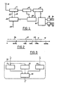
- Figure 1 is a block diagram of a scan tuning FM receiver according to the prior art.
- Figure 2 is a logarithmic plot showing frequency ranges for various signal components present within an FM receiver.
- Figure 3 is a block diagram showing a signal quality detecting circuit according to the present invention.
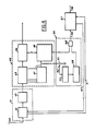
- Figure 4 is a block diagram showing a scan tunning FM receiver employing a stop circuit according to the present invention.
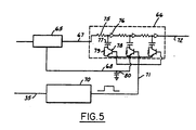
- FIG. 5 is a schematic and block diagram showing an FM noise controller according to the present invention.
- FIG. 1 shows a well known FM receiver architecture including an antenna 10, an RF section 11, an IF section 12, a demodulator 13, a stereo decoder 14, left and right audio amplifiers 15 and 17, and stereo speakers 16 and 18.
- Electronic tuning of the FM receiver is accomplished by means of a scan tuner 20 which provides a tuning voltage over a line 21 to RF section 11.
- a local oscillator contained in RF section 11 provides a local oscillator signal used for deriving an intermediate frequency.
- the local oscillator signal is also provided from RF section 11 to scan tuner 20 over a line 22 for implementing electronic control over the RF tuning using a phase locked loop, for example.
- Scan tuning of the FM receiver is implemented by sweeping the tuning voltage provided over line 21 in response to a start signal 23 provided to scan tuner 20. Sweeping of the tuning voltage continues automatically until an FM signal is received meeting the criteria for identifying a signal of a predetermined quality.
- a stop signal 24 is provided to scan tuner 20 from a stop circuit 25.
- An intensity signal is provided from IF section 12 to stop circuit 25 and an automatic frequency control (AFC) signal is provided from demodulator 13 to stop circuit 25.
- AFC automatic frequency control
- stop circuit 25 generates a stop signal in response to the intensity signal being above a predetermined intensity and the AFC signal being within a frequency window to indicate that the station is accurately tuned in.
- the conventional stop circuit shown in Figure 1 has the disadvantage that it may stop on a sideband of a strong signal, or on a signal contaminated by noise or interference.
- the present invention analyzes an additional characteristic of the signal to produce a high quality FM signal detector.
- FIG. 2 shows a signal spectrum within an FM receiver plotted on a logarithmic scale.
- An FM receiver output is affected by broadband noise which is present across the entire spectrum.
- a range of frequencies 26 is identified which includes FM broadcast signals and harmonics.
- the FM signals include the stereo sum baseband channel from zero to 15 KHz, a pilot signal at 19 KHz, stereo difference channel sidebands extending from 23 KHz to 53 KHz, and a subsidiary communication authorization (SCA) signal from 60 to 74 KHz.
- the FM signal also includes a subcarrier at 57 KHz for modulating traffic and other information according to the Radio Data System (RDS) employed there. Harmonics from these various FM signals appear in the FM receiver extending up to the upper end of range 26 at about 100 KHz to about 150 KHz.
- the harmonics or other nonlinear products from signal mixing are caused by IF filters and limiting amplifiers, for example.
- a range of frequencies 28 extends from 5 MHz and higher and includes intermediate frequency signals and radio frequency signals orginating in tuned-in or nearly tuned-in FM broadcasts.
- the intermediate frequency of an accurately tuned in signal is located at about 10.7 MHz, but IF signals from adjacent channels can appear somewhat below 10.7 MHz.
- the signals present in the FM receiver in frequency ranges 26 and 28 contain the information content of the desired FM signal being received. However, a range of frequencies 27 extending from about 100 KHz to about 5 MHz contains noise only. Frequency range 27 lacks any signal components related to the intelligence contained in the FM signal being received and is used herein to derive a measure of signal noise which is not masked by the information signal content.
- Figure 3 shows a quality detecting circuit 30 including a noise detector 31 receiving the field intensity signal produced by a conventional IF detector (not shown).
- the field intensity signal is sometimes referred to as the stereo blend signal.
- the intensity signal is further provided to a level detector 32.
- the AFC signal provided by a conventional demodulator (not shown) is input to a window detector 33.
- the outputs of noise detector 31, level detector 32, and window detector 33 are respectively input to a logic circuit 34.
- the output of logic circuit 34 provides an indicating signal 35 which can be employed as a stop signal, for example.
- noise detector 31 isolates that frequency range of the intensity signal which contains no components related to the FM signal intelligence.
- the isolated noise signal is compared to a predetermined value and a signal is provided to logic circuit 34 when the isolated noise signal is below the predetermined value.
- Level detector 32 compares the intensity signal to a predetermined intensity and produces an output signal transmitted to logic circuit 34 when the intensity signal is greater than the predetermined intensity.
- Window detector 33 compares the AFC signal to a pair of window threshold values and generates an output signal which is coupled to logic circuit 34 when the AFC signal is within the predetermined window to indicate that the FM station is accurately tuned in.
- Logic circuit 34 preferably performs an AND function for generating indicating signal 35 when signals from noise detector 31, level detector 32, and window detector 33 are simultaneously received.
- FIG. 4 shows an FM scan tuning receiver having a stop circuit according to the present invention and using typical integrated circuits for major portions of the receiver.
- An antenna 40 is coupled to a receiver front end IC 41.
- IC 41 includes an FM tuner 42 and an IF amplifier and filter section 43.
- the output of IF amplifier and filter section 43 is connected to an multistage IF limiting amplifier 45 in an IF demodulating system IC 44.
- the amplitude limited IF signal from multistage amplifier 45 is coupled to an FM demodulator 46 which provides a composite audio output having stereo sum and difference channels.
- Each amplifying stage in multistage amplifier 45 is connected to an IF level detector 47 that generates an intensity signal which is proportional to the field intensity at which the FM signal is being received.
- the intensity signal is provided to a level detector and frequency window detector 48 which also receives an AFC signal from FM demodulator 46.
- Detector 48 provides an output signal to one input of an AND gate 55 in a high quality detector circuit 50.
- Quality detector circuit 50 implements the functions of quality detecting circuit 30 ( Figure 3) that are not already implemented in IC 44 in Figure 4. In other words, level detector and frequency window detector 48 performs the functions of level detector 32, window detector 33, and part of logic circuit 34 in Figure 3.
- the intensity signal from IF level detector 47 is provided across a threshold setting potentiometer 51.
- a threshold tap 52 couples an attenuated intensity signal to a bandpass filter 53.
- the filtered intensity signal is provided from bandpass filter 53 to a noise amplifier and peak detector 54.
- Potentiometer 51, filter 53, and noise amplifier and detector 54 correspond to noise detector 31 in Figure 3.
- the output of detector 54 is connected to the remaining input of AND gate 55.
- the output of AND gate 55 provides a stop signal (i.e., indicating signal) 56 which is coupled to a microprocessor-controlled phase locked loop scan tuning circuit 57.
- Circuit 57 receives a start signal 58 in response to operator actuation of a scan tuning operation.
- a phase lock loop tuning voltage 60 is provided from circuit 57 to FM tuner 42 which contains a local oscillator.
- the local oscillator signal 61 is provided from FM tuner 42 to scan tuning circuit 57.
- bandpass filter 53 provides a noise signal not related to FM signal intelligence by virtue of the pass band of bandpass filter 53 being in the range from 100 KHz to about 5 MHz.
- bandpass filter 53 has a lower cutoff frequency equal to about 200 KHz and an upper cutoff frequency equal to about 2 MHz or has a smaller passband within that range.
- Detector 54 detects the peak value of the filtered noise and compares the detected peak value with a predetermined peak value. Detector 54 generates a high logic signal output when the noise signal is below a predetermined peak value.
- detector 48 If the intensity signal is greater than the predetermined intensity and if the frequency error signal (i.e., AFC signal) is within the frequency window, then detector 48 also generates a high logic level output and AND gate 55 generates a high level output. The resulting stop signal 56 stops a scan tuning operation only on received signals of the highest quality. By virtue of the pass band of bandpass filter 53, scanning will not stop on any FM signal including an unacceptable level of any noise including thermal noise, adjacent channel interference noise, multipass distortion noise, overmodulation noise, or digital noise.
- the frequency error signal i.e., AFC signal
- a demodulator 65 receives an IF signal to produce a composite audio output on a line 67.
- Composite audio output 67 is passed through a switchable low-pass filter 66 to generate a filtered composite audio output 72.
- Filter 66 preferably includes a plurality of stages, each having a series connected resistor 75 and operational amplifier 76.
- a filter-stage switch transistor 78 has a collector coupled to the junction of resistor 75 and operational amplifier 76 through a capacitor 77. The emitter of transistor 78 is connected to a DC reference voltage 68 provided by demodulator 65.
- the collector and emitter of transistor 78 are coupled by a resistor 79 which has a higher resistance than resistor 75 and keeps capacitor 77 at the DC reference voltage independent of the state of transistor 78.
- a capacitor 80 is coupled between the line carrying DC reference voltage 68 and ground.
- Indicating signal 35 from quality detecting circuit 30 ( Figure 3) is provided to the input of a monostable multivibrator 70.
- a filter control pulse is provided from monostable multivibrator 70 over a line 71 to the base of filter switch transistors 78.
- the logic level of indicating signal 35 is high when the FM signal being received has a high quality.
- Monostable multivibrator 70 is provided such that it will be triggered to generate an output pulse by a negative going transition of indicating signal 35. While indicating signal 35 remains high, there is no control pulse over line 71 to switch on filter 66. Therefore, composite audio output 67 is passed through filter 66 unchanged to provide the filtered composite signal 72. When interference or noise is present in the received FM signal, indicating signal 35 will oscillate between high and low states.
- a filter control pulse of a predetermined duration is generated by monostable multivibrator 70 to activate low pass filter 66.
- the characteristics of low pass filter 66 are such that frequencies below about 19 KHz (i.e., frequencies containing the stereo sum channel and the FM pilot signal) are substantially unaffected while higher frequencies which include the stereo difference sidebands are attenuated.
- DC reference voltage 68 is applied to the emitters of switching transistor 78 to provide the same biasing DC potential to the filter as is present in the composite output of the demodulator 65 in order to avoid audio pops when the filter is switched to an active or an inactive state.
- demodulator 65 and filter 66 are biased to the same DC reference voltage such that their outputs swing about the same voltage thereby avoiding a change in bias level when filter 66 is switched on or off.
Landscapes
- Engineering & Computer Science (AREA)
- Computer Networks & Wireless Communication (AREA)
- Signal Processing (AREA)
- Noise Elimination (AREA)
Applications Claiming Priority (2)
| Application Number | Priority Date | Filing Date | Title |
|---|---|---|---|
| US07/443,624 US5125105A (en) | 1989-11-30 | 1989-11-30 | High-quality reception indicating circuit for fm receivers |
| US443624 | 1989-11-30 |
Publications (3)
| Publication Number | Publication Date |
|---|---|
| EP0430469A2 true EP0430469A2 (de) | 1991-06-05 |
| EP0430469A3 EP0430469A3 (en) | 1992-05-27 |
| EP0430469B1 EP0430469B1 (de) | 1995-10-18 |
Family
ID=23761549
Family Applications (1)
| Application Number | Title | Priority Date | Filing Date |
|---|---|---|---|
| EP90312233A Expired - Lifetime EP0430469B1 (de) | 1989-11-30 | 1990-11-08 | Schaltung zur Signalqualitätsbestimmung für FM-Empfänger |
Country Status (4)
| Country | Link |
|---|---|
| US (1) | US5125105A (de) |
| EP (1) | EP0430469B1 (de) |
| CA (1) | CA2026811A1 (de) |
| DE (1) | DE69023100T2 (de) |
Cited By (4)
| Publication number | Priority date | Publication date | Assignee | Title |
|---|---|---|---|---|
| WO2001001572A1 (de) * | 1999-06-23 | 2001-01-04 | Infineon Technologies Ag | Integrierte schaltung zur detektion eines empfangssignals sowie schaltungsanordnung |
| WO2003105342A1 (en) * | 2002-06-07 | 2003-12-18 | Koninklijke Philips Electronics N.V. | Method and apparatus for auto-tuning of a radio fm-receiver |
| EP2034614A2 (de) | 2007-09-04 | 2009-03-11 | SANYO ELECTRIC Co., Ltd. | FM-Tuner |
| EP2359482A4 (de) * | 2008-12-15 | 2012-09-26 | Panasonic Automotive Sys Co Am | Verfahren und vorrichtung zur kokanal-interferenzerkennung in einem funkgerät |
Families Citing this family (32)
| Publication number | Priority date | Publication date | Assignee | Title |
|---|---|---|---|---|
| JP3046842B2 (ja) * | 1992-04-24 | 2000-05-29 | モトローラ・インコーポレーテッド | 送信信号の信号伝送品質レベルの決定方法及び装置 |
| KR100289630B1 (ko) * | 1992-07-13 | 2001-05-02 | 리패치 | 무선 랜의 출력제어방법 및 장치 |
| DE4226346A1 (de) * | 1992-08-08 | 1994-02-10 | Philips Patentverwaltung | Schaltungsanordnung zur Bestimmung der Feldstärke von FM-Sendern |
| DE4309518A1 (de) * | 1993-03-24 | 1994-10-06 | Blaupunkt Werke Gmbh | Schaltungsanordnung zur Ableitung mindestens eines von der Qualität eines empfangenen Signals abhängigen Qualitätssignals |
| DE4311933A1 (de) * | 1993-04-10 | 1994-10-13 | Blaupunkt Werke Gmbh | Schaltungsanordnung zur Erzeugung eines Stopp-Signals für einen Sendersuchlauf |
| JPH07111484A (ja) * | 1993-08-20 | 1995-04-25 | Hitachi Ltd | 無線通信装置 |
| JPH07106921A (ja) * | 1993-10-08 | 1995-04-21 | Uniden Corp | 高速走査無線受信機 |
| MA23383A1 (fr) * | 1993-12-03 | 1995-07-01 | Scientific Atlanta | Procede et dispositif pour localiser et suivre une porteuse qpsk |
| JP3483295B2 (ja) * | 1994-04-15 | 2004-01-06 | 富士通株式会社 | 周辺ゾーンキャリア監視方式および移動局 |
| US5555451A (en) * | 1994-06-13 | 1996-09-10 | Ford Motor Company | High-quality reception indicating circuit for scanning AM recievers |
| US5671286A (en) * | 1995-06-09 | 1997-09-23 | Ford Motor Company | Strategy for controlling FM stereo separation and frequency response in noisy reception environments |
| US6493544B1 (en) * | 1996-05-15 | 2002-12-10 | Daimlerchrysler Corporation | FM signal quality detector during seek |
| US6476878B1 (en) * | 1998-10-21 | 2002-11-05 | Scientific-Atlanta, Inc. | Method and apparatus for audio signal processing |
| US7127010B1 (en) * | 1999-07-29 | 2006-10-24 | Bose Corporation | Oscillator controlling |
| US6463266B1 (en) * | 1999-08-10 | 2002-10-08 | Broadcom Corporation | Radio frequency control for communications systems |
| JP2002325028A (ja) * | 2001-04-26 | 2002-11-08 | General Res Of Electronics Inc | 周波数走査形受信機 |
| US7006797B1 (en) * | 2001-05-21 | 2006-02-28 | Counter Technologies, Llc | Coherence frequency determining system and associated radio apparatus |
| US7031680B2 (en) * | 2002-12-05 | 2006-04-18 | Freescale Semiconductor, Inc. | Stop-on-station method and apparatus |
| US7366606B2 (en) * | 2004-04-06 | 2008-04-29 | Honda Motor Co., Ltd. | Method for refining traffic flow data |
| TWI317240B (en) * | 2006-07-05 | 2009-11-11 | Asustek Comp Inc | Anti-pop circuit |
| JP2008017292A (ja) * | 2006-07-07 | 2008-01-24 | Denso Corp | ラジオ放送受信装置およびラジオ放送の自動選局装置 |
| CA2661711C (en) * | 2006-08-31 | 2013-07-09 | Clarion Co., Ltd. | Broadcast receiver and broadcast channel seek method |
| GB0624982D0 (en) * | 2006-12-14 | 2007-01-24 | Cambridge Silicon Radio Ltd | FM signal quality measurement |
| US20080233869A1 (en) * | 2007-03-19 | 2008-09-25 | Thomas Baker | Method and system for a single-chip fm tuning system for transmit and receive antennas |
| US7869779B2 (en) * | 2007-05-30 | 2011-01-11 | Broadcom Corporation | Method and system for processing channels in a FM communication system |
| US7937053B2 (en) * | 2007-06-08 | 2011-05-03 | Himax Technologies Limited | Method for receiving station signal and receiver for receiving the same |
| JP2009105727A (ja) * | 2007-10-24 | 2009-05-14 | Sanyo Electric Co Ltd | Fm受信機 |
| US20090247101A1 (en) * | 2008-03-28 | 2009-10-01 | Ligang Zhang | Auto-detection of broadcast channel spacing |
| US8600331B2 (en) * | 2012-04-11 | 2013-12-03 | Black Berry Limited | Radio receiver with reconfigurable baseband channel filter |
| US9031567B2 (en) | 2012-12-28 | 2015-05-12 | Spreadtrum Communications Usa Inc. | Method and apparatus for transmitter optimization based on allocated transmission band |
| US9197266B2 (en) * | 2014-01-30 | 2015-11-24 | Qualcomm Technologies International, Ltd. | Low current RSSI detector |
| WO2018031301A1 (en) | 2016-08-08 | 2018-02-15 | Goldman Sachs & Co. LLC | Systems and methods for learning and predicting time-series data using inertial auto-encoders |
Family Cites Families (19)
| Publication number | Priority date | Publication date | Assignee | Title |
|---|---|---|---|---|
| US3934206A (en) * | 1974-09-26 | 1976-01-20 | Rockwell International Corporation | Receiver with adjustable squelch |
| US3947774A (en) * | 1974-11-25 | 1976-03-30 | General Motors Corporation | Signal seeking stopping circuit receiver |
| US3984776A (en) * | 1975-11-19 | 1976-10-05 | Motorola, Inc. | Signal quality detector |
| US4087641A (en) * | 1976-04-01 | 1978-05-02 | Pioneer Electronic Corporation | Noise limiting circuit for FM stereo receiver |
| JPS6012365Y2 (ja) * | 1978-10-20 | 1985-04-22 | ヤマハ株式会社 | 受信機の雑音除去回路 |
| NL7810859A (nl) * | 1978-11-01 | 1980-05-06 | Philips Nv | Fm-ontvanger met zenderzoekinrichting. |
| US4198543A (en) * | 1979-01-19 | 1980-04-15 | General Motors Corporation | Stereo composite processor for stereo radio receiver |
| US4262363A (en) * | 1979-08-08 | 1981-04-14 | General Motors Corporation | Signal seeking stop circuit for amplitude modulated receiver |
| US4376207A (en) * | 1980-08-18 | 1983-03-08 | Hoffmann-La Roche Inc. | Chiral synthesis of amino sugars |
| JPS57212819A (en) * | 1981-06-24 | 1982-12-27 | Sharp Corp | Automatic tuning storage receiver |
| JPS5980015A (ja) * | 1982-10-29 | 1984-05-09 | Pioneer Electronic Corp | チユ−ナの同調周波数設定動作指令発生装置 |
| US4577226A (en) * | 1982-11-30 | 1986-03-18 | Rca Corporation | Noise reduction for FM stereophonic systems and particularly useful in television audio systems |
| US4538300A (en) * | 1983-09-07 | 1985-08-27 | Sprague Electric Company | Linear signal strength detector in AM radio |
| US4580285A (en) * | 1983-09-07 | 1986-04-01 | Sprague Electric Company | Scanning AM radio with discriminator-driven-scan-stop-circuit |
| JPS6178230A (ja) * | 1984-09-26 | 1986-04-21 | Nec Corp | 集積化am/fm切換回路 |
| US4761829A (en) * | 1985-11-27 | 1988-08-02 | Motorola Inc. | Adaptive signal strength and/or ambient noise driven audio shaping system |
| DE8816338U1 (de) * | 1988-03-26 | 1989-07-06 | Blaupunkt-Werke Gmbh, 3200 Hildesheim | Autoradio mit einer Schaltungsanordnung zur Feststellung empfangsortbedingter Störungen |
| US4947456A (en) * | 1988-09-16 | 1990-08-07 | Uniden America Corporation | Scanning radio receiver |
| US4975953A (en) * | 1989-01-13 | 1990-12-04 | Delco Electronics Corporation | Combined deemphasis circuit and noise blanker |
-
1989
- 1989-11-30 US US07/443,624 patent/US5125105A/en not_active Expired - Lifetime
-
1990
- 1990-10-03 CA CA002026811A patent/CA2026811A1/en not_active Abandoned
- 1990-11-08 DE DE69023100T patent/DE69023100T2/de not_active Expired - Fee Related
- 1990-11-08 EP EP90312233A patent/EP0430469B1/de not_active Expired - Lifetime
Cited By (9)
| Publication number | Priority date | Publication date | Assignee | Title |
|---|---|---|---|---|
| WO2001001572A1 (de) * | 1999-06-23 | 2001-01-04 | Infineon Technologies Ag | Integrierte schaltung zur detektion eines empfangssignals sowie schaltungsanordnung |
| US6674813B2 (en) | 1999-06-23 | 2004-01-06 | Infineon Technologies Ag | Integrated circuit for detecting a received signal and circuit configuration |
| WO2003105342A1 (en) * | 2002-06-07 | 2003-12-18 | Koninklijke Philips Electronics N.V. | Method and apparatus for auto-tuning of a radio fm-receiver |
| US7848720B2 (en) | 2002-06-07 | 2010-12-07 | Nxp B.V. | Method and apparatus for auto-tuning of a radio fm-receiver |
| EP2034614A2 (de) | 2007-09-04 | 2009-03-11 | SANYO ELECTRIC Co., Ltd. | FM-Tuner |
| EP2034614A3 (de) * | 2007-09-04 | 2009-11-18 | SANYO ELECTRIC Co., Ltd. | FM-Tuner |
| US8135370B2 (en) | 2007-09-04 | 2012-03-13 | Sanyo Electric Co., Ltd. | FM tuner having adaptive bandpass filter for adjacent channel interference |
| CN101383623B (zh) * | 2007-09-04 | 2012-07-25 | 三洋电机株式会社 | Fm调谐器 |
| EP2359482A4 (de) * | 2008-12-15 | 2012-09-26 | Panasonic Automotive Sys Co Am | Verfahren und vorrichtung zur kokanal-interferenzerkennung in einem funkgerät |
Also Published As
| Publication number | Publication date |
|---|---|
| US5125105A (en) | 1992-06-23 |
| EP0430469B1 (de) | 1995-10-18 |
| DE69023100T2 (de) | 1996-03-21 |
| CA2026811A1 (en) | 1991-05-31 |
| EP0430469A3 (en) | 1992-05-27 |
| DE69023100D1 (de) | 1995-11-23 |
Similar Documents
| Publication | Publication Date | Title |
|---|---|---|
| US5125105A (en) | High-quality reception indicating circuit for fm receivers | |
| US5222255A (en) | Intermodulation controller for radio receiver | |
| US5339454A (en) | Automatic gain control for RF amplifier | |
| US5073976A (en) | Signal-to-noise ratio indicating circuit for fm receivers | |
| EP2034614B1 (de) | FM-Tuner | |
| US4356567A (en) | Radio receiver with bandwidth switching | |
| US5307515A (en) | Adjacent channel controller for radio receiver | |
| US5390345A (en) | Method for preventing desensitization and radio interference of radio receivers | |
| US5249233A (en) | Multipath noise minimizer for radio receiver | |
| US4249261A (en) | Superheterodyne radio receiver with nearby-station interference detection | |
| EP0688107B1 (de) | AM-Funkempfänger | |
| US4726073A (en) | Receiver including a multipath transmission detector | |
| US5483694A (en) | Radio receiver with an intermodulation detector | |
| US5408685A (en) | Multipath detector using phase comparison of stereo pilot signal | |
| US4580286A (en) | Noise activated mute for FM reception in an AM/FM radio receiver | |
| US4661996A (en) | Method and apparatus for indicating radio frequency carrier loss in remotely controlled vehicles | |
| JPH02194736A (ja) | Fmラジオ受信機 | |
| US4504973A (en) | Automatic disabling of AFC/AFT controller during receiver circuit tuning | |
| JPS60212038A (ja) | 受信機 | |
| KR20010012983A (ko) | 진폭 변조 질 검출기 | |
| EP0132307A2 (de) | Empfänger mit Störsperre | |
| KR890001537Y1 (ko) | 위성 텔레비죤 방송수신기의 음성 중간주파수 대역폭 자동 절환회로 | |
| JPH0423441B2 (de) | ||
| JPH0638569B2 (ja) | 受信機の自動利得制御回路 | |
| JPH0897738A (ja) | ラジオ受信機 |
Legal Events
| Date | Code | Title | Description |
|---|---|---|---|
| PUAI | Public reference made under article 153(3) epc to a published international application that has entered the european phase |
Free format text: ORIGINAL CODE: 0009012 |
|
| AK | Designated contracting states |
Kind code of ref document: A2 Designated state(s): DE FR GB |
|
| PUAL | Search report despatched |
Free format text: ORIGINAL CODE: 0009013 |
|
| AK | Designated contracting states |
Kind code of ref document: A3 Designated state(s): DE FR GB |
|
| 17P | Request for examination filed |
Effective date: 19920929 |
|
| 17Q | First examination report despatched |
Effective date: 19940623 |
|
| GRAA | (expected) grant |
Free format text: ORIGINAL CODE: 0009210 |
|
| AK | Designated contracting states |
Kind code of ref document: B1 Designated state(s): DE FR GB |
|
| REF | Corresponds to: |
Ref document number: 69023100 Country of ref document: DE Date of ref document: 19951123 |
|
| ET | Fr: translation filed | ||
| PLBE | No opposition filed within time limit |
Free format text: ORIGINAL CODE: 0009261 |
|
| STAA | Information on the status of an ep patent application or granted ep patent |
Free format text: STATUS: NO OPPOSITION FILED WITHIN TIME LIMIT |
|
| 26N | No opposition filed | ||
| REG | Reference to a national code |
Ref country code: GB Ref legal event code: 746 Effective date: 19961003 |
|
| REG | Reference to a national code |
Ref country code: FR Ref legal event code: D6 |
|
| PGFP | Annual fee paid to national office [announced via postgrant information from national office to epo] |
Ref country code: FR Payment date: 19981110 Year of fee payment: 9 |
|
| PG25 | Lapsed in a contracting state [announced via postgrant information from national office to epo] |
Ref country code: FR Free format text: LAPSE BECAUSE OF NON-PAYMENT OF DUE FEES Effective date: 20000731 |
|
| REG | Reference to a national code |
Ref country code: FR Ref legal event code: ST |
|
| REG | Reference to a national code |
Ref country code: GB Ref legal event code: IF02 |
|
| PGFP | Annual fee paid to national office [announced via postgrant information from national office to epo] |
Ref country code: DE Payment date: 20041117 Year of fee payment: 15 |
|
| PGFP | Annual fee paid to national office [announced via postgrant information from national office to epo] |
Ref country code: GB Payment date: 20041122 Year of fee payment: 15 |
|
| PG25 | Lapsed in a contracting state [announced via postgrant information from national office to epo] |
Ref country code: GB Free format text: LAPSE BECAUSE OF NON-PAYMENT OF DUE FEES Effective date: 20051108 |
|
| PG25 | Lapsed in a contracting state [announced via postgrant information from national office to epo] |
Ref country code: DE Free format text: LAPSE BECAUSE OF NON-PAYMENT OF DUE FEES Effective date: 20060601 |
|
| GBPC | Gb: european patent ceased through non-payment of renewal fee |
Effective date: 20051108 |