EP0430909B1 - Procédé de laminage à chaud pour tubes sous soudure à réduction préliminaire du diamètre du produits semi-finis - Google Patents
Procédé de laminage à chaud pour tubes sous soudure à réduction préliminaire du diamètre du produits semi-finis Download PDFInfo
- Publication number
- EP0430909B1 EP0430909B1 EP90830558A EP90830558A EP0430909B1 EP 0430909 B1 EP0430909 B1 EP 0430909B1 EP 90830558 A EP90830558 A EP 90830558A EP 90830558 A EP90830558 A EP 90830558A EP 0430909 B1 EP0430909 B1 EP 0430909B1
- Authority
- EP
- European Patent Office
- Prior art keywords
- mandrel
- mill
- rolling
- blank
- coreless
- Prior art date
- Legal status (The legal status is an assumption and is not a legal conclusion. Google has not performed a legal analysis and makes no representation as to the accuracy of the status listed.)
- Expired - Lifetime
Links
- 230000009467 reduction Effects 0.000 title claims description 19
- 238000005098 hot rolling Methods 0.000 title claims description 6
- 239000011265 semifinished product Substances 0.000 title 1
- 238000005096 rolling process Methods 0.000 claims description 50
- 238000000034 method Methods 0.000 claims description 23
- 230000008569 process Effects 0.000 claims description 20
- 238000004519 manufacturing process Methods 0.000 claims description 8
- 238000010438 heat treatment Methods 0.000 claims description 5
- 238000011144 upstream manufacturing Methods 0.000 claims description 5
- 239000011248 coating agent Substances 0.000 claims 1
- 238000000576 coating method Methods 0.000 claims 1
- 239000000126 substance Substances 0.000 claims 1
- 230000008901 benefit Effects 0.000 description 5
- 238000007599 discharging Methods 0.000 description 5
- 229910000831 Steel Inorganic materials 0.000 description 4
- 238000009749 continuous casting Methods 0.000 description 4
- 239000010959 steel Substances 0.000 description 4
- 239000002184 metal Substances 0.000 description 3
- 230000003647 oxidation Effects 0.000 description 3
- 238000007254 oxidation reaction Methods 0.000 description 3
- 238000001816 cooling Methods 0.000 description 2
- 238000010586 diagram Methods 0.000 description 2
- 238000005516 engineering process Methods 0.000 description 2
- 229910001092 metal group alloy Inorganic materials 0.000 description 2
- 238000012545 processing Methods 0.000 description 2
- 230000008859 change Effects 0.000 description 1
- 238000007796 conventional method Methods 0.000 description 1
- 230000003247 decreasing effect Effects 0.000 description 1
- 230000000694 effects Effects 0.000 description 1
- 238000009434 installation Methods 0.000 description 1
- 239000000463 material Substances 0.000 description 1
- 239000000155 melt Substances 0.000 description 1
- 230000004048 modification Effects 0.000 description 1
- 238000012986 modification Methods 0.000 description 1
- 238000005457 optimization Methods 0.000 description 1
- 238000013386 optimize process Methods 0.000 description 1
- 238000002360 preparation method Methods 0.000 description 1
- 239000007858 starting material Substances 0.000 description 1
- 238000012546 transfer Methods 0.000 description 1
Images

Classifications
-
- B—PERFORMING OPERATIONS; TRANSPORTING
- B21—MECHANICAL METAL-WORKING WITHOUT ESSENTIALLY REMOVING MATERIAL; PUNCHING METAL
- B21B—ROLLING OF METAL
- B21B23/00—Tube-rolling not restricted to methods provided for in only one of groups B21B17/00, B21B19/00, B21B21/00, e.g. combined processes planetary tube rolling, auxiliary arrangements, e.g. lubricating, special tube blanks, continuous casting combined with tube rolling
-
- B—PERFORMING OPERATIONS; TRANSPORTING
- B21—MECHANICAL METAL-WORKING WITHOUT ESSENTIALLY REMOVING MATERIAL; PUNCHING METAL
- B21B—ROLLING OF METAL
- B21B17/00—Tube-rolling by rollers of which the axes are arranged essentially perpendicular to the axis of the work, e.g. "axial" tube-rolling
- B21B17/02—Tube-rolling by rollers of which the axes are arranged essentially perpendicular to the axis of the work, e.g. "axial" tube-rolling with mandrel, i.e. the mandrel rod contacts the rolled tube over the rod length
- B21B17/04—Tube-rolling by rollers of which the axes are arranged essentially perpendicular to the axis of the work, e.g. "axial" tube-rolling with mandrel, i.e. the mandrel rod contacts the rolled tube over the rod length in a continuous process
-
- B—PERFORMING OPERATIONS; TRANSPORTING
- B21—MECHANICAL METAL-WORKING WITHOUT ESSENTIALLY REMOVING MATERIAL; PUNCHING METAL
- B21B—ROLLING OF METAL
- B21B17/00—Tube-rolling by rollers of which the axes are arranged essentially perpendicular to the axis of the work, e.g. "axial" tube-rolling
- B21B17/14—Tube-rolling by rollers of which the axes are arranged essentially perpendicular to the axis of the work, e.g. "axial" tube-rolling without mandrel, e.g. stretch-reducing mills
-
- B—PERFORMING OPERATIONS; TRANSPORTING
- B21—MECHANICAL METAL-WORKING WITHOUT ESSENTIALLY REMOVING MATERIAL; PUNCHING METAL
- B21B—ROLLING OF METAL
- B21B25/00—Mandrels for metal tube rolling mills, e.g. mandrels of the types used in the methods covered by group B21B17/00; Accessories or auxiliary means therefor ; Construction of, or alloys for, mandrels or plugs
- B21B25/04—Cooling or lubricating mandrels during operation
Definitions
- the present invention relates to an improved hot-rolling process for seamless tubes with preliminary diameter reduction of the pierced round blanks by means of a rolling mill for blanks reduction of the conventional type.
- a piercing mill with skew rolls to obtain from said billet a hollow body of big thickness, being called "pierced blank”
- a continuous rolling mill formed of a series of multi-rolls stands which, by rolling the blank on a mandrel previously fed therein, progressively reduces the thickness thereof down to a size near to the finished tube size
- a drawing mill formed of a series of stands with two or more rolls each for coreless reducing the outer diameter until reaching the desired final size.
- the number, arrangement and constructional characteristics of the machines upstream of the rolling mill may vary, according to the needs, to follow the requirements of the common technological knowledges.
- the limits imposed to the various machines by technology and layout define the cross-section reductions which are possible, and consequently the diameter size at the various rolling steps.
- the diameters of the initial round billets are chosen and determined according to the diameter size that is desired for the finished products.
- a precise series of outer diameters of the finished tube can be obtained, which series is defined by the structural features of both the continuous rolling mill and the drawing mill.
- the least expensive technology of manufacturing the raw round billet is that of the continuous casting process from the melt metal, then using directly the billet without preliminary processing before forming the pierced blank.
- the continuous casting process is particularly advantageous, under the point of view of both the manufacturing costs and the quality of the product, only for diameter sizes greater than minimum size which may be defined, according to the present state of the art, as a minimum value of the billet diameter of 150 mm.
- minimum size which may be defined, according to the present state of the art, as a minimum value of the billet diameter of 150 mm.
- a particular method of optimization of a plant designed to manufacture finished tubes with outer diameter of 20-90 mm would require to start from a round billet having a diameter of 120 mm, i.e. less than the minimum size that can be satisfactorily produced by the most common continuous casting plants.
- a billet of this size not only is of a quality that not always is reliable, but also is expensive and hardly available in the trade.
- a rolling mill for reducing the diameter of pierced blanks has been used for some time to reduce the outer diameter of the billet already pierced by a piercing mill with skew rolls, thus modifying the outer diameter from a size that is more convenient for the continuous casting plants to a size required to enter the rolling mill with mandrel.
- the correspondence between the initial diameter of the billet and that of the finished tube is made less rigidly univocal, whereby the number of diameter sizes of the raw billets which are required for a given range of diameter sizes of the finished tubes may be reduced, thus simplifying the supplying operation through a less differentiated stored stock.
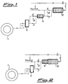
- the apparatus for reducing the blank diameter is installed as a separate machine between the piercing mill with skew rolls and the rolling mill with mandrel according to a layout as shown in Fig. 1.
- This layout shows, with respect to a non-optimized plant, i.e.
- JP-A60-102211 discloses a method for the manufacture of thick steel tubes according to which the coreless reduction step is distinct from a final rolling step on mandrel, the latter being carried out by means of caliber rolls to obtain finished products.
- This method provides for merely making longer the continuous rolling mill by increasing the number of stands, thus having this final operation in line, but only because no previous preparation of the pierced blank is foreseen.
- a first consequence is that not actually round shapes are obtained, in particular of the inner tubular walls, as shown by the drawings of this prior patent.
- the process according to the invention comprising a step of coreless reduction of the pierced blank diameter before its continuous rolling on a mandrel, is characterized by the fact that said reduction step of the blank without mandrel is carried out immediately before and on the same line of the continuous rolling step on mandrel, without intermediate transferring of the blank and at the same time as the mandrel is driven into the blank, without touching it, at the location of said reducing mill.
- Fig. 1 shows a diagrammatic representation or a layout of a known plant carrying out the conventional process of manufacturing seamless tubes, being optimized by the fact of comprising a coreless reducing mill 6 of the pierced blanks between the piercing mill 2 and the continuous rolling mill 10 with mandrel.
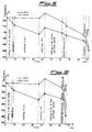
- a coreless reducing mill 6 of the pierced blanks between the piercing mill 2 and the continuous rolling mill 10 with mandrel In the foregoing it has been already observed which are the inconveniences due to the space being occupied, the increasing of costs and the longer time of processing that results in a considerable cooling until reaching temperature values which, at the continuous rolling mill on mandrel, are near to or even lower than the values generally admitted for rolling, of about 1180°C (for the steel), as can be seen in Fig. 8.
- Fig. 8 Referring to Fig.
- the process according to the invention provides for causing a bar or billet to exit from heating oven, carrying the same to a piercing mill 2 and feeding the pierced blank therefrom, through transfer lines 3, 4, 5 to a pierced blank reducing mill 6 which is designed and made according to the prior art, and according to the invention is installed directly upstream of, adjacent to a rolling mill 10 with mandrel, whereby these machines form a single unit.
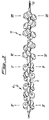
- the operating steps of the process according to the invention comprise, subsequent to discharging the bar from the heating oven 1 and its carrying to the piercing mill 2, the handling of pierced blank to the mandrel feeding station, where the mandrel is driven into the pierced blank, then passing together with the latter through the blank reducing mill and the rolling mill on mandrel 10 in an immediate succession, as is better seen in Fig. 3, in which 11 designates the pierced blank and 12 the mandrel.
- Mandrel and pierced blank come into contact each other only starting from the first stand of rolling mill 10, as it occurred in the prior art.
- speed and mutual spacing between rolls of the stands of the blank reducing mill 6 are adjusted automatically for this purpose, e.g. by means of a programmable logic suitable to control at the same time two machines at different speeds, so that at each moment the mandrel position is the prefixed one.
- the synchronization of the various parts of the plant and the exact feeding of pierced blank to the first stand of rolling mill are ensured automatically and under whichever condition.
- mandrel 12 being present at the inside of the pierced blank 11 when passing through the reducing stands 6 puts a limit to oxidation of the blank inner surface, owing to the decreased cross-section for passage of air caused by mandrel 12 and possible presence of antioxidizer agents provided on the mandrel surface. This effect is of course the more important, the greater is the affinity with air shown by the blank metal.
Landscapes
- Engineering & Computer Science (AREA)
- Mechanical Engineering (AREA)
- Metal Rolling (AREA)
- Control Of Metal Rolling (AREA)
- Casting Or Compression Moulding Of Plastics Or The Like (AREA)
- Pressure Welding/Diffusion-Bonding (AREA)
Claims (5)
- Procédé de laminage à chaud pour tubes sans soudure de diamètre extérieur pas plus grand que 170 mm et obtenus par perçage par galets de biais d'une billette ronde obtenue par coulée continue et réchauffée, comprenant une réduction sans mandrin (6) du diamètre de l'ébauche percée (11) avant son laminage continu (10) sur un mandrin (12),
caractérisé par le fait que l'opération (6) de réduction sans mandrin est réalisée sur la même ligne (5) que l'opération de laminage continu (10) immédiatement en amont de celle-ci, qui est effectuée en utilisant un mandrin, sans transfert intermédiaire de l'ébauche (11) et en même temps que l'insertion du mandrin (12) dans l'ébauche sans qu'elle la touche, à l'endroit du laminoir de réduction (10). - Procédé selon la revendication 1,
caractérisé en ce que les ébauches percées (11) et les mandrins (12) traversent coaxialement le laminoir de réduction sans mandrin (6) et sans interférer entre eux jusqu'à ce qu'ils parviennent au premier jeu de galets du laminoir (10) dans lequel l'ébauche (11) et le mandrin (12) viennent au contact. - Procédé selon la revendication 1 ou 2,
caractérisé par l'opération supplémentaire consistant à revêtir le mandrin (12) avec des substances anti-oxydantes sur toute sa surface latérale. - Installation de laminage pour la fabrication par laminage à chaud de tubes sans soudure de diamètre extérieur pas plus grand que 170 mm à partir d'une billette ronde obtenue par coulée continue, comprenant un four de chauffage (1), une perceuse (2) à galets de biais, un laminoir de réduction de diamètre sans mandrin pour les ébauches percées (11) et un laminoir continu (10) à mandrins (12) avec un poste d'alimentation pour insérer des mandrins (12) dans les ébauches (11),
caractérisée par le fait que le laminoir de réduction (6) est disposé immédiatement en amont du laminoir continu (10) et sur la même ligne que la station d'alimentation (5) en formant ainsi un ensemble unique. - Installation selon la revendication 4,
caractérisée en ce qu'elle comprend en outre des moyens de commande automatiques pour les laminoirs et les jeux de galets du laminoir de réduction (6) qui sont interverrouillés aux moyens de commande du laminoir (10), de sorte qu'à tous moments et quelles que soient les conditions il y ait synchronisation des différentes parties de l'installation avec un positionnement correct du mandrin.
Priority Applications (1)
| Application Number | Priority Date | Filing Date | Title |
|---|---|---|---|
| AT90830558T ATE102089T1 (de) | 1989-11-30 | 1990-11-29 | Warmwalzverfahren fuer nahtlose rohre mit vorausgehender verringerung des durchmessers von halbzeug. |
Applications Claiming Priority (2)
| Application Number | Priority Date | Filing Date | Title |
|---|---|---|---|
| IT02255989A IT1238224B (it) | 1989-11-30 | 1989-11-30 | Processo perfezionato di laminazione a caldo di tubi senza saldatura con preventiva riduzione degli sbozzati forati |
| IT2255989 | 1989-11-30 |
Publications (3)
| Publication Number | Publication Date |
|---|---|
| EP0430909A2 EP0430909A2 (fr) | 1991-06-05 |
| EP0430909A3 EP0430909A3 (en) | 1991-10-02 |
| EP0430909B1 true EP0430909B1 (fr) | 1994-03-02 |
Family
ID=11197830
Family Applications (1)
| Application Number | Title | Priority Date | Filing Date |
|---|---|---|---|
| EP90830558A Expired - Lifetime EP0430909B1 (fr) | 1989-11-30 | 1990-11-29 | Procédé de laminage à chaud pour tubes sous soudure à réduction préliminaire du diamètre du produits semi-finis |
Country Status (10)
| Country | Link |
|---|---|
| US (1) | US5109689A (fr) |
| EP (1) | EP0430909B1 (fr) |
| CN (1) | CN1020682C (fr) |
| AR (1) | AR245392A1 (fr) |
| AT (1) | ATE102089T1 (fr) |
| DE (1) | DE69007033T2 (fr) |
| ES (1) | ES2050416T3 (fr) |
| IT (1) | IT1238224B (fr) |
| PL (1) | PL287993A1 (fr) |
| RU (1) | RU2036031C1 (fr) |
Families Citing this family (11)
| Publication number | Priority date | Publication date | Assignee | Title |
|---|---|---|---|---|
| FR2662632B1 (fr) * | 1990-05-30 | 1992-10-30 | Plastic Omnium Cie | Procede pour la realisation de tubes minces en resine fluoree notamment en polytetrafluorethylene. |
| DE69219586T2 (de) * | 1991-01-22 | 1997-09-25 | Pipe Rehab International, Inc., Memphis, Tenn. | Verfahren zur durchmesserverkleinerung und zur auskleidung von einem röhrenförmigen gegenstand |
| MX9702792A (es) * | 1994-10-20 | 1998-02-28 | Sumitomo Metal Ind | Procedimiento para fabricar tubos de acero sin costura. |
| JP3855300B2 (ja) * | 1996-04-19 | 2006-12-06 | 住友金属工業株式会社 | 継目無鋼管の製造方法および製造設備 |
| RU2214312C2 (ru) * | 2001-07-26 | 2003-10-20 | ОАО "Челябинский трубопрокатный завод" | Способ производства труб из труднодеформируемых марок стали и сплавов с повышенным коэффициентом линейного расширения |
| TWI265053B (en) | 2004-01-16 | 2006-11-01 | Sumitomo Metal Ind | Method for producing seamless pipe |
| JP4873012B2 (ja) * | 2006-10-16 | 2012-02-08 | 住友金属工業株式会社 | マンドレルミル及び継目無管の製造方法 |
| DE102008050771A1 (de) * | 2008-10-08 | 2010-04-29 | Geotomographie Gmbh | Erzeugung seismischer Wellen in Bohrungen mit elektromagnetischen Impulswandlern |
| DE102008061141B4 (de) * | 2008-12-09 | 2012-08-30 | Sumitomo Metal Industries, Ltd. | Verfahren zur Herstellung nahtloser Rohre mittels eines Drei-Walzen-Stangenwalzwerks |
| CN102974615B (zh) * | 2012-11-08 | 2015-07-15 | 聊城市开发区全运钢管制造有限公司 | 圆钢穿孔衬芯轧制工艺方法 |
| CN114558891B (zh) * | 2022-03-04 | 2024-05-24 | 贵州捷盛钻具股份有限公司 | 钎杆用中空钢热轧方法、中空钢及热轧机 |
Citations (1)
| Publication number | Priority date | Publication date | Assignee | Title |
|---|---|---|---|---|
| JPS5630015A (en) * | 1979-08-20 | 1981-03-26 | Nippon Steel Corp | Continuous rolling method for pipe |
Family Cites Families (12)
| Publication number | Priority date | Publication date | Assignee | Title |
|---|---|---|---|---|
| US1499535A (en) * | 1922-08-12 | 1924-07-01 | John A Katzenmeyer | Method of manufacturing tubes and a continuous mill therefor |
| FR783354A (fr) * | 1933-12-28 | 1935-07-11 | Schloemann Ag | Procédé et dispositif pour rétreindre les tubes |
| SU418234A1 (ru) * | 1968-11-23 | 1974-03-05 | Ю. И. Блинов, М. А. Шубин, Ю. В. Самар нов , И. П. Макаров | Способ прокатки труб с натяжением на редукционном стане |
| GB1557872A (en) * | 1976-09-15 | 1979-12-12 | Shevchenko A A | Others method of continuous tube rolling and rolling mill therefor |
| DE2755058A1 (de) * | 1977-12-08 | 1979-06-13 | Mannesmann Ag | Verfahren zum herstellen nahtloser rohre auf einer stossbank |
| US4318294A (en) * | 1978-12-29 | 1982-03-09 | Nippon Steel Corporation | Method of manufacturing seamless metal pipes and tubes |
| FR2469962A1 (fr) * | 1979-11-21 | 1981-05-29 | Vallourec | Procede et dispositif pour la fabrication d'un tube d'acier sans soudure par laminage a chaud sur mandrin |
| DE3136381A1 (de) * | 1981-09-14 | 1983-04-14 | Kocks Technik Gmbh & Co, 4010 Hilden | Walzwerksanlage zur herstellung nahtloser rohre |
| DE3140015A1 (de) * | 1981-10-08 | 1983-04-21 | Kocks Technik Gmbh & Co, 4010 Hilden | Anlage zum herstellen nahtloser rohre |
| DE3309797A1 (de) * | 1983-03-18 | 1984-09-20 | Kocks Technik Gmbh & Co, 4010 Hilden | Verfahren und anlage zum herstellen nahtloser rohre |
| JPS60102211A (ja) * | 1983-11-08 | 1985-06-06 | Sumitomo Metal Ind Ltd | 厚肉鋼管の製造方法 |
| US4798071A (en) * | 1986-06-25 | 1989-01-17 | Kocks Technik Gmbh & Co. | Seamless tube production |
-
1989
- 1989-11-30 IT IT02255989A patent/IT1238224B/it active IP Right Grant
-
1990
- 1990-11-26 AR AR90318469A patent/AR245392A1/es active
- 1990-11-27 US US07/619,188 patent/US5109689A/en not_active Expired - Fee Related
- 1990-11-28 PL PL28799390A patent/PL287993A1/xx unknown
- 1990-11-29 ES ES90830558T patent/ES2050416T3/es not_active Expired - Lifetime
- 1990-11-29 DE DE69007033T patent/DE69007033T2/de not_active Expired - Fee Related
- 1990-11-29 EP EP90830558A patent/EP0430909B1/fr not_active Expired - Lifetime
- 1990-11-29 RU SU904831834A patent/RU2036031C1/ru active
- 1990-11-29 CN CN90109547A patent/CN1020682C/zh not_active Expired - Fee Related
- 1990-11-29 AT AT90830558T patent/ATE102089T1/de active
Patent Citations (1)
| Publication number | Priority date | Publication date | Assignee | Title |
|---|---|---|---|---|
| JPS5630015A (en) * | 1979-08-20 | 1981-03-26 | Nippon Steel Corp | Continuous rolling method for pipe |
Also Published As
| Publication number | Publication date |
|---|---|
| PL287993A1 (en) | 1991-12-02 |
| CN1020682C (zh) | 1993-05-19 |
| IT1238224B (it) | 1993-07-12 |
| EP0430909A3 (en) | 1991-10-02 |
| DE69007033T2 (de) | 1994-06-01 |
| IT8922559A0 (it) | 1989-11-30 |
| US5109689A (en) | 1992-05-05 |
| ATE102089T1 (de) | 1994-03-15 |
| RU2036031C1 (ru) | 1995-05-27 |
| EP0430909A2 (fr) | 1991-06-05 |
| AR245392A1 (es) | 1994-01-31 |
| IT8922559A1 (it) | 1991-05-30 |
| ES2050416T3 (es) | 1994-05-16 |
| DE69007033D1 (de) | 1994-04-07 |
| CN1052063A (zh) | 1991-06-12 |
Similar Documents
| Publication | Publication Date | Title |
|---|---|---|
| US5501091A (en) | Method and apparatus for elongating metal tubes by means of a mandrel mill | |
| US5109689A (en) | Hot-rolling process for seamless tubes with preliminary diameter reduction of the semifinished products | |
| JPH11285708A (ja) | シ―ムレス鋼管を製造する方法及び装置 | |
| EP2521626B1 (fr) | Laminoir de tube et procédé de laminage des tubes sans soudure | |
| GB1593526A (en) | Rolling mill plant | |
| US4289011A (en) | Continuous pipe rolling process | |
| US4571970A (en) | Rolling mill plant for the manufacture of seamless tubes | |
| GB2074485A (en) | Rolling mill | |
| CN116890033B (zh) | 一种管材制备方法 | |
| CA1179170A (fr) | Methode de fabrication de tuyaux sans couture | |
| US3604238A (en) | Apparatus for the production of steel pipes by extrusion | |
| WO2011030273A2 (fr) | Installation pour le laminage de tubes | |
| JP3624235B2 (ja) | 鋼管の延伸圧延制御方法 | |
| SU1761320A1 (ru) | Способ прокатки биметаллических труб на пилигримовом стане | |
| GB2099346A (en) | Tube rolling mill | |
| GB2098900A (en) | Manufacture of seamless metal tubing | |
| CN111922081B (zh) | 一种异型镁合金型材连续铸轧与轧制短流程制备方法 | |
| JP2000246310A (ja) | 継目無管の製造方法 | |
| US1903296A (en) | Apparatus for tube manufacture | |
| SU749467A1 (ru) | Способ получени гильз на прошивном стане | |
| SU1611470A1 (ru) | Способ холодной прокатки многослойных труб | |
| JPS58119416A (ja) | 継目無管の肉厚制御方法 | |
| SU580920A1 (ru) | Способ винтовой прокатки | |
| SU1068180A1 (ru) | Способ прокатки металлов | |
| SU880525A1 (ru) | Способ пилигримовой прокатки труб |
Legal Events
| Date | Code | Title | Description |
|---|---|---|---|
| PUAI | Public reference made under article 153(3) epc to a published international application that has entered the european phase |
Free format text: ORIGINAL CODE: 0009012 |
|
| AK | Designated contracting states |
Kind code of ref document: A2 Designated state(s): AT BE CH DE ES FR GB GR LI SE |
|
| PUAL | Search report despatched |
Free format text: ORIGINAL CODE: 0009013 |
|
| AK | Designated contracting states |
Kind code of ref document: A3 Designated state(s): AT BE CH DE ES FR GB GR LI SE |
|
| 17P | Request for examination filed |
Effective date: 19920317 |
|
| 17Q | First examination report despatched |
Effective date: 19920820 |
|
| GRAA | (expected) grant |
Free format text: ORIGINAL CODE: 0009210 |
|
| AK | Designated contracting states |
Kind code of ref document: B1 Designated state(s): AT BE CH DE ES FR GB GR LI SE |
|
| REF | Corresponds to: |
Ref document number: 102089 Country of ref document: AT Date of ref document: 19940315 Kind code of ref document: T |
|
| REF | Corresponds to: |
Ref document number: 69007033 Country of ref document: DE Date of ref document: 19940407 |
|
| ET | Fr: translation filed | ||
| REG | Reference to a national code |
Ref country code: ES Ref legal event code: FG2A Ref document number: 2050416 Country of ref document: ES Kind code of ref document: T3 |
|
| REG | Reference to a national code |
Ref country code: GR Ref legal event code: FG4A Free format text: 3010950 |
|
| PLBE | No opposition filed within time limit |
Free format text: ORIGINAL CODE: 0009261 |
|
| STAA | Information on the status of an ep patent application or granted ep patent |
Free format text: STATUS: NO OPPOSITION FILED WITHIN TIME LIMIT |
|
| EAL | Se: european patent in force in sweden |
Ref document number: 90830558.4 |
|
| 26N | No opposition filed | ||
| PGFP | Annual fee paid to national office [announced via postgrant information from national office to epo] |
Ref country code: GB Payment date: 19951017 Year of fee payment: 6 |
|
| PGFP | Annual fee paid to national office [announced via postgrant information from national office to epo] |
Ref country code: SE Payment date: 19951018 Year of fee payment: 6 |
|
| PGFP | Annual fee paid to national office [announced via postgrant information from national office to epo] |
Ref country code: BE Payment date: 19951023 Year of fee payment: 6 |
|
| PGFP | Annual fee paid to national office [announced via postgrant information from national office to epo] |
Ref country code: GR Payment date: 19951025 Year of fee payment: 6 |
|
| PGFP | Annual fee paid to national office [announced via postgrant information from national office to epo] |
Ref country code: ES Payment date: 19961115 Year of fee payment: 7 |
|
| PGFP | Annual fee paid to national office [announced via postgrant information from national office to epo] |
Ref country code: FR Payment date: 19961126 Year of fee payment: 7 |
|
| PGFP | Annual fee paid to national office [announced via postgrant information from national office to epo] |
Ref country code: DE Payment date: 19961127 Year of fee payment: 7 |
|
| PG25 | Lapsed in a contracting state [announced via postgrant information from national office to epo] |
Ref country code: GB Effective date: 19961129 |
|
| PGFP | Annual fee paid to national office [announced via postgrant information from national office to epo] |
Ref country code: AT Payment date: 19961129 Year of fee payment: 7 |
|
| PG25 | Lapsed in a contracting state [announced via postgrant information from national office to epo] |
Ref country code: SE Effective date: 19961130 Ref country code: BE Effective date: 19961130 |
|
| PGFP | Annual fee paid to national office [announced via postgrant information from national office to epo] |
Ref country code: CH Payment date: 19961219 Year of fee payment: 7 |
|
| BERE | Be: lapsed |
Owner name: DALMINE S.P.A. Effective date: 19961130 |
|
| PG25 | Lapsed in a contracting state [announced via postgrant information from national office to epo] |
Ref country code: GR Free format text: THE PATENT HAS BEEN ANNULLED BY A DECISION OF A NATIONAL AUTHORITY Effective date: 19970531 |
|
| REG | Reference to a national code |
Ref country code: GR Ref legal event code: MM2A Free format text: 3010950 |
|
| GBPC | Gb: european patent ceased through non-payment of renewal fee |
Effective date: 19961129 |
|
| EUG | Se: european patent has lapsed |
Ref document number: 90830558.4 |
|
| PG25 | Lapsed in a contracting state [announced via postgrant information from national office to epo] |
Ref country code: AT Free format text: LAPSE BECAUSE OF NON-PAYMENT OF DUE FEES Effective date: 19971129 |
|
| PG25 | Lapsed in a contracting state [announced via postgrant information from national office to epo] |
Ref country code: LI Free format text: LAPSE BECAUSE OF NON-PAYMENT OF DUE FEES Effective date: 19971130 Ref country code: FR Free format text: THE PATENT HAS BEEN ANNULLED BY A DECISION OF A NATIONAL AUTHORITY Effective date: 19971130 Ref country code: ES Free format text: LAPSE BECAUSE OF NON-PAYMENT OF DUE FEES Effective date: 19971130 Ref country code: CH Free format text: LAPSE BECAUSE OF NON-PAYMENT OF DUE FEES Effective date: 19971130 |
|
| REG | Reference to a national code |
Ref country code: CH Ref legal event code: PL |
|
| PG25 | Lapsed in a contracting state [announced via postgrant information from national office to epo] |
Ref country code: DE Free format text: LAPSE BECAUSE OF NON-PAYMENT OF DUE FEES Effective date: 19980801 |
|
| REG | Reference to a national code |
Ref country code: FR Ref legal event code: ST |
|
| REG | Reference to a national code |
Ref country code: ES Ref legal event code: FD2A Effective date: 19981212 |