EP0431016B1 - Möbelstücke - Google Patents
Möbelstücke Download PDFInfo
- Publication number
- EP0431016B1 EP0431016B1 EP89909592A EP89909592A EP0431016B1 EP 0431016 B1 EP0431016 B1 EP 0431016B1 EP 89909592 A EP89909592 A EP 89909592A EP 89909592 A EP89909592 A EP 89909592A EP 0431016 B1 EP0431016 B1 EP 0431016B1
- Authority
- EP
- European Patent Office
- Prior art keywords
- work top
- furniture
- piece
- base structure
- extension means
- Prior art date
- Legal status (The legal status is an assumption and is not a legal conclusion. Google has not performed a legal analysis and makes no representation as to the accuracy of the status listed.)
- Expired - Lifetime
Links
- 230000003019 stabilising effect Effects 0.000 claims description 4
- 230000008878 coupling Effects 0.000 claims 2
- 238000010168 coupling process Methods 0.000 claims 2
- 238000005859 coupling reaction Methods 0.000 claims 2
- 230000009977 dual effect Effects 0.000 abstract description 5
- 239000002184 metal Substances 0.000 description 3
- 239000002023 wood Substances 0.000 description 2
- 239000000872 buffer Substances 0.000 description 1
- 230000001419 dependent effect Effects 0.000 description 1
- 239000000463 material Substances 0.000 description 1
- 239000002905 metal composite material Substances 0.000 description 1
- 238000000034 method Methods 0.000 description 1
- 239000007787 solid Substances 0.000 description 1
Images




Classifications
-
- A—HUMAN NECESSITIES
- A47—FURNITURE; DOMESTIC ARTICLES OR APPLIANCES; COFFEE MILLS; SPICE MILLS; SUCTION CLEANERS IN GENERAL
- A47B—TABLES; DESKS; OFFICE FURNITURE; CABINETS; DRAWERS; GENERAL DETAILS OF FURNITURE
- A47B9/00—Tables with tops of variable height
- A47B9/18—Tables with tops of variable height with additional top or additional legs for varying the height of the top
-
- A—HUMAN NECESSITIES
- A47—FURNITURE; DOMESTIC ARTICLES OR APPLIANCES; COFFEE MILLS; SPICE MILLS; SUCTION CLEANERS IN GENERAL
- A47B—TABLES; DESKS; OFFICE FURNITURE; CABINETS; DRAWERS; GENERAL DETAILS OF FURNITURE
- A47B9/00—Tables with tops of variable height
- A47B2009/006—Tables with tops of variable height of two distinct heights, e.g. coffee table - dining table
-
- A—HUMAN NECESSITIES
- A47—FURNITURE; DOMESTIC ARTICLES OR APPLIANCES; COFFEE MILLS; SPICE MILLS; SUCTION CLEANERS IN GENERAL
- A47B—TABLES; DESKS; OFFICE FURNITURE; CABINETS; DRAWERS; GENERAL DETAILS OF FURNITURE
- A47B2200/00—General construction of tables or desks
- A47B2200/0035—Tables or desks with features relating to adjustability or folding
- A47B2200/0039—Two position height adjustable table
Definitions
- the present invention relates to a piece of furniture and more especially to a table.
- US-A-4303 018 shows such a convertible dual-mode table in accordance with the pre-characterising portion of Claim 1 but the mechanism in this patent for setting the table top in the raised and lowered conditions is relatively complex and the arrangement is not particularly suited for use with a table top of elongate rectangular form, being rather more intended for use with a circular table top.
- a piece of furniture especially a table, comprising a fixed base structure, a work top, extension means located between the fixed base structure and the work top comprising swingable support members (11) which in a first position set the work top (3) substantially level with the top of the base structure (2) and at a first height (H1) above a floor datum (D-D) while in a second elevated position the work top (2) is set at an increased height (H2) above said first height (H1), said swingable support member (11) being pivotally connected to the fixed base structure (2) at pivot means (7, 23), stabilising means (12A) are provided to stabilise the extension means (4) when the work top (3) is in said second relatively elevated position, characterised in that each swingable support member (11) comprises a double-arm lever (12/12A, 33/33A), one arm (12A, 33A) of each double-arm lever being in the form of a tail defining said stabilising means, said tails (12A, 33A) of the swingable member (11) firmly engaging the fixed base structure (2)
- the extension means comprises a pair of swingable support members which, adjacent one end, are pivotally attached to the base structure, the other end of each support member being slidably coupled to the work top by a pin-and-slot arrangement at the work top whereby the swingable support members can be swung from a lowered position whereat said work top occupies said first position to a raised position to place said work top in said second raised position.
- Automatic locking means can be provided to automatically lock the extension means in the open extended condition.
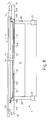
- a dual-mode table 1 has a first mode (Fig. 1) as a coffee table and a second mode (Fig. 4) as a dining table.
- the table 1 generally comprises a legged base structure 2, a work top 3 and extension means 4 located between the base structure 2 and the work top 3 whereby the top 3 can be set at the relatively lower position of Fig 1 or at the relatively higher position of Fig 4.
- the table top height (H1) in Fig 1 can be the norm for coffee tables, say about 15 ins (38 cm) while in Fig 4 the top height (H1 + H2) will be suitable for dining purposes, say about 29 ins (73,5 cm).
- the base structure 2 comprises two pairs of legs 5, 6 (Fig 2), upper and lower cross bars 7, 8 of circular cross section joining the legs 5, 6 of each leg pair and longitudinal frame members 9 linking the bars 7, 8 of each leg pair, each member 9 including an upwardly facing recess 10.
- Each extension means 4 comprises a one-piece (ie unarticulated) frame 11 of ladder form with side bars 12 and cross members 13, each frame 11 being pivotally mounted on a respective cross-bar 7.
- the inner ends of the frame 11 (Fig. 1) are slidably coupled to the work top 3 by means of pin members 14 engaging in slots 15 in longitudinal plates 16 (of angle form) attached to the underside of the work top 3.
- Each slot 15 includes an axial portion 15A which co-operates with the pin member 14 of the associated frame 11 for raising of the work top 3 when the frame 11 is swung upwardly while, to assist retainment of the work top 3 in the raised position, to outer end of each slot 15 has a portion 15B which extends laterally to the portion 15A and curves backwardly to receive the pin member 14 in a locked condition.
- the side bars 12 of the frame 11 included tail portions 12 A which abut against the bars 8, when the extension means 4 are swung to the raised position, to set the frames 11 in the upright position (Fig. 4) with the work top 3 raised.
- the angle form plates 16 on the work top 3 rest against the cross bar 7 of the base structure 2 so that the work top 3 is substantially at the level of the top of the base structure 2.
- the work top 3 is moved from a low setting where the top 3 is at a high H1 above a floor datum D-D through a height H2 to the high setting.
- the extension means 4 enable movement of the work top 4 between the settings to be simple and straightforward.
- Figs. 7(a) - 7(e) to move the top 3 to the elevated (dining) setting, one of the frames 11 is swung upwardly (Fig. 7b) to the raised condition so that the associated pin member 14 is locked in slot-portion 15B, then a similar operation is carried out on the other frame 11 (Fig. 7d, e).
- the extension means 4 enable the raised height H2 of the table top 3 to be at least 0.75 H1 and even greater so that the top 3 can be set relatively low for the first mode (i.e. as a coffee table) but nevertheless be set substantially high for the second mode (i.e. in the dining table mode).
- the base structure 2 has end uprights 20 of solid form mounted on base support 21, and a single central beam 22 of rectangular cross-section joins the uprights 20.
- the use of this single beam 22 gives improved leg room when the table top 3 is in the raised dining mode (Fig. 10).
- the frames 11 are pivotally coupled to the uprights 20 via pins 23 while the tail portions 12A of the frames 11 abut against buffers 24 in the lower surface of table top 3 in the top lowered condition (Fig. 8).
- the lower surface of the top 3 also carries a rib structure 25 to which the slot-plates 16 are attached, and lugs 26 on the tail portions 12A abut against the uprights 20 in the raised condition (Fig. 11) to stabilize the extension means 4.
- Figs. 8-11 is set in exactly the same manner as shown in Figs 7(a)-(e).
- each extension means is in the form of a concertina frame device 4A.
- Each concertina frame device 4A comprises a double-frame set 31, 32.
- a first frame 31 of the set includes longitudinal members 33 journalled to a respective cross-bar 7 of the base structure 2 and cross bar 34, 35 between the members 33, the members 33 lying to the outside of the frame members 9, while the second frame 32 of the set has longitudinal members 36 which lie in respective recesses 30 in the lowered position and which are swingably coupled at one end to a transverse rib 37 of the table top 3 by the pins 38.
- the top edge of each frame device 4A is offset from the pins 38 so that when the top edge is in engagement with the table top 3 (Fig 13) the table top 3 and the frame device 4A are precluded from adopting an obtuse angle.
- the members 36 are journalled at the other end to the cross bar 35 of frame 31 to provide the concertina swinging action of the frames 31, 32 the members 36 being recessed to allow the bar 34 to nest in the members 36 in the closed condition.
- the members 33 include tail portions 33A which press against the lower cross bars 8 of the base structure 2 to stabilize the concertina device 4A when the devices 4A are in the open extended condition (Fig. 13).
- locking cams 39 are provided on the frames 32 which co-operate with locking plates 40 in the frames 31.
- the cams 39 are secured to a cross bar 41 rotatably carried by the members 36, the cams 39 being urged into the locking position by coil springs 42 on the bar 41, and each cam 39 includes an inclined nose portion 39A whereby the cam 39 can be swung back by the plate 40 to enable the plate 40 to lock automatically in the recess of the cam.
- a manual release knob 43 is carried by the bar 41.
- the table 1 in each embodiment may be made essentially of wood, but other material could be utilized - for example a wood/metal composite structure is possible with say the various cross bars of metal eg tubes.
- the plates 16 are preferably of metal. It would be possible to have a design where the base structure 2 and the extension means 4 are essentially of tubular metal form.
- the legs 5,6 are shown as having a circular cross section but a rectangular cross-section is of course possible.
Landscapes
- Tables And Desks Characterized By Structural Shape (AREA)
Claims (14)
- Möbel, insbesondere ein Tisch, mit einer festgelegten Basisstruktur, einem Arbeitsaufsatz bzw. einer Arbeitsoberfläche, einer Verlängerungs- bzw. Auszieheinrichtung, die zwischen der festegelegten Basisstruktur und dem Arbeitsaufsatz angeordnet ist, mit schwenkbaren Stützelementen (11), die den Arbeitsaufsatz (3) bei einer ersten Position im wesentlichen auf eine Ebene mit der Oberseite der Basisstruktur (2) und auf eine erste Höhe (H1) über einer Bodenbezugslinie (D-D) setzen, während in einer zweiten erhöhten Position der Arbeitsaufsatz (2) auf eine gesteigerte Höhe (H2) über der ersten Höhe (H1) gesetzt wird, wobei die schwenkbaren Stützelemente (11) schwenkbar bzw. gelenkig mit der festgelegten Basisstruktur (2) bei einer Schwenkeinrichtung (7, 23) verbunden sind, wobei eine Stabilisierungseinrichtung (12A) vorgesehen ist, um die Verlängerungseinrichtung (4) zu stabilisieren, wenn der Arbeitsaufsatz (3) in der zweiten, relativ erhöhten Position ist, dadurch gekennzeichnet, daß jedes schwenkbare Stützelement (11) einen Doppelarmhebel (12/12A, 33/33A) aufweist, wobei ein Arm (12A, 33A) von jedem Doppelarmhebel in der Form eines Schwanzes vorliegt, der die Stabilisierungseinrichtung definiert, wobei die Schwänze (12A, 33A) der schwenkbaren Elemente (11) fest an der festgelegten Basisstruktur (2) bei Punkten (8) angreifen, die von der Schwenkeinrichtung (7, 23) beabstandet sind, um die Stützelemente (11) zu stabilisieren, wenn die Verlängerungseinrichtung (4) in einem verlängerten Zustand ist, und daß eine freigebbare Verriegelungseinrichtung (15B, 39) für jedes schwenkbare Stützelement (11) vorgesehen ist, um das Stützelement in der zweiten erhöhten Position zu verriegeln.
- Möbel nach Anspruch 1, dadurch gekennzeichnet, daß jede Verlängerungseinrichtung (4A) und der Arbeitsaufsatz (3) Oberflächenpositionen aufweisen, die aneinander anstoßen unter Begrenzung der relativen Schwenkbewegung zwischen der Verlängerungseinrichtung (4A) und dem Arbeitsaufsatz (3).
- Möbel nach Anspruch 1 oder 2, dadurch gekennzeichnet, daß die gesteigerte Höhe (H2) zumindest drei Viertel der ersten Höhe (H1) beträgt.
- Möbel nach einem der vorhergehenden Ansprüche, dadurch gekennzeichnet, daß der Arbeitsaufsatz (3) auf der Basisstruktur (2) in der ersten Position liegt.
- Möbel nach einem der vorhergehenden Ansprüche, dadurch gekennzeichnet, daß die Verlängerungseinrichtung (4) ein Paar von schwenkbaren Stützelementen (11) aufweist, die, benachbart einem Ende, schwenkbar an der Basisstruktur (2) angebracht sind, wobei das andere Ende von jedem Stützelement gleitbar mit dem Arbeitsaufsatz (3) durch eine Koppeleinrichtung (14, 15) an bzw. bei dem Arbeitsaufsatz (3) gekoppelt bzw. verbunden ist, wodurch die schwenkbaren Stützelemente (11) von einer abgesenkten Position, bei der der Arbeitsaufsatz (3) die erste Position einnimmt, zu einer erhobenen Position geschwenkt werden können, um den Arbeitsaufsatz (3) in der zweiten erhobenen Position anzuordnen.
- Möbel nach Anspruch 5, dadurch gekennzeichnet, daß die Koppeleinrichtung (14, 15) eine Stift-und-Schlitz-Anordnung aufweist.
- Möbel nach Anspruch 5, dadurch gekennzeichnet, daß der Schlitz der Stift-und-Schlitz-Anordnung (14, 15) einen ersten Achsenabschnitt (15A) aufweist, der mit dem Stift (14) zusammenarbeitet, um den Arbeitsaufsatz (3) anzuheben, wenn die Stützelemente (11) in Richtung auf die erhöhte Position geschwenkt werden, und einen Endschlitzabschnitt (15B) aufweist, der dazu dient, die Verlängerungseinrichtung (4) in der zweiten erhöhten Position zu verriegeln.
- Möbel nach Anspruch 7, dadurch gekennzeichnet, daß der laterale Endschlitzabschnitt (15B) sich nach hinten krümmt bzw. zurückbiegt.
- Möbel nach Anspruch 1, dadurch gekennzeichnet, daß die freigebbare Verriegelungseinrichtung eine federvorgespannte Hebeleinrichtung (39, 42) aufweist, die das schwenkbare Stützelement (4A) automatisch in der zweiten erhöhten Position verriegelt.
- Möbel nach Anspruch 9, dadurch gekennzeichnet, daß die Hebeleinrichtung (39, 42) benachbart zu dem Arbeitsaufsatz angeordnet ist, wenn das schwenkbare Stützelement (4A) in der zweiten erhöhten Position ist.
- Möbel nach einem der vorhergehenden Ansprüche, dadurch gekennzeichnet, daß die schwenkbaren Stützelemente (11) in entgegengesetzter Beziehung angeordnet sind, wenn die Verlängerungseinrichtung (4) in der ersten abgesenkten Position ist.
- Möbel nach einem der vorhergehenden Ansprüche, dadurch gekennzeichnet, daß die Basisstruktur Endträger (20) und zumindest ein Längselement (22) aufweist, welches die Endträger (20) verbindet, wobei der Arbeitsaufsatz (3) im wesentlichen von rechteckiger Form ist.
- Möbel nach Anspruch 12, dadurch gekennzeichnet, daß ein zentrales Längselement (22) vorgesehen ist.
- Möbel nach einem der Ansprüche 1 bis 3, dadurch gekennzeichnet, daß die Verlängerungseinrichtung in der Form einer ziehharmonikaartigen Einrichtung (4A, Fig. 12, 13) vorliegt, wobei die ziehharmonikaartige Einrichtung ein Paar von Doppelrahmensätzen (31, 32) aufweist, wobei jeder Doppelrahmensatz (31, 32) einen ersten und einen zweiten Rahmen hat, die mit der Basisstruktur (2) bzw. dem Arbeitsaufsatz (3) verbunden sind und zusätzlich schwenkbar miteinander verbunden sind, wodurch die Rahmen (31, 32) auf eine ziehharmonikaartige Weise zwischen einem geschlossenen zurückgezogenen Zustand und einem offenen verlängerten Zustand geschwenkt werden können.
Priority Applications (1)
| Application Number | Priority Date | Filing Date | Title |
|---|---|---|---|
| AT89909592T ATE94734T1 (de) | 1988-08-11 | 1989-08-10 | Moebelstuecke. |
Applications Claiming Priority (4)
| Application Number | Priority Date | Filing Date | Title |
|---|---|---|---|
| GB8819076 | 1988-08-11 | ||
| GB888819076A GB8819076D0 (en) | 1988-08-11 | 1988-08-11 | Piece of furniture |
| GB898911874A GB8911874D0 (en) | 1988-08-11 | 1989-05-24 | Piece of furniture |
| GB8911874 | 1989-05-24 |
Publications (2)
| Publication Number | Publication Date |
|---|---|
| EP0431016A1 EP0431016A1 (de) | 1991-06-12 |
| EP0431016B1 true EP0431016B1 (de) | 1993-09-22 |
Family
ID=26294262
Family Applications (1)
| Application Number | Title | Priority Date | Filing Date |
|---|---|---|---|
| EP89909592A Expired - Lifetime EP0431016B1 (de) | 1988-08-11 | 1989-08-10 | Möbelstücke |
Country Status (5)
| Country | Link |
|---|---|
| US (1) | US5280753A (de) |
| EP (1) | EP0431016B1 (de) |
| JP (1) | JPH04500022A (de) |
| DE (1) | DE68909414D1 (de) |
| WO (1) | WO1990001282A1 (de) |
Cited By (1)
| Publication number | Priority date | Publication date | Assignee | Title |
|---|---|---|---|---|
| US10968937B2 (en) | 2018-06-08 | 2021-04-06 | Siso A/S | Multifunctional mounting bracket |
Families Citing this family (7)
| Publication number | Priority date | Publication date | Assignee | Title |
|---|---|---|---|---|
| USD354643S (en) | 1992-10-14 | 1995-01-24 | Gesiika Buromobelwerk GmbH & Co. | Table |
| US6401630B1 (en) | 2000-02-09 | 2002-06-11 | William F. Peterson | Convertible article of furniture |
| US7220185B2 (en) * | 2005-10-12 | 2007-05-22 | Chien-Yeh Chen | Height-adjustable game table |
| ES2565253B1 (es) * | 2015-12-02 | 2016-12-12 | Fama Sofas, S.L. | Estructura de mesa convertible |
| AT519325B1 (de) * | 2016-11-11 | 2018-08-15 | Schiestl Franz | Couchtisch mit einer abnehmbaren Tischplatte und einem Tischgestell |
| FR3121022A1 (fr) * | 2021-03-28 | 2022-09-30 | Valentin Lefebvre | Mécanisme de table escamotable relevable |
| US12114769B1 (en) | 2023-01-10 | 2024-10-15 | Christopher James Day | Convertible table with integrated storage |
Family Cites Families (10)
| Publication number | Priority date | Publication date | Assignee | Title |
|---|---|---|---|---|
| US928726A (en) * | 1908-12-24 | 1909-07-20 | Guy Henry Witthaus | Disappearing table. |
| FR908851A (fr) * | 1945-01-22 | 1946-04-22 | Table transformable | |
| GB659265A (en) * | 1948-10-27 | 1951-10-17 | Ferguson Bros Mfg Co | Improvements in or relating to a table of adjustable height |
| US2544229A (en) * | 1950-01-12 | 1951-03-06 | Hoppe Boris | Vertically adjustable table construction |
| US2582791A (en) * | 1950-07-06 | 1952-01-15 | Earl L Page | Vertically adjustable table |
| US2643923A (en) * | 1951-06-04 | 1953-06-30 | Floyd E Beall | Vertically adjustable table |
| FR1130763A (fr) * | 1955-08-25 | 1957-02-12 | Table transformable en hauteur | |
| US4161915A (en) * | 1977-07-19 | 1979-07-24 | Avalanche Limited | Adjustable table |
| US4237795A (en) * | 1978-10-20 | 1980-12-09 | Daystrom Furniture, Inc. | Dual height table |
| US4259909A (en) * | 1979-05-07 | 1981-04-07 | Casimiro Belina | Vertically adjustable table |
-
1989
- 1989-08-10 WO PCT/GB1989/000916 patent/WO1990001282A1/en not_active Ceased
- 1989-08-10 JP JP1508992A patent/JPH04500022A/ja active Pending
- 1989-08-10 EP EP89909592A patent/EP0431016B1/de not_active Expired - Lifetime
- 1989-08-10 US US07/655,386 patent/US5280753A/en not_active Expired - Fee Related
- 1989-08-10 DE DE89909592T patent/DE68909414D1/de not_active Expired - Lifetime
Cited By (1)
| Publication number | Priority date | Publication date | Assignee | Title |
|---|---|---|---|---|
| US10968937B2 (en) | 2018-06-08 | 2021-04-06 | Siso A/S | Multifunctional mounting bracket |
Also Published As
| Publication number | Publication date |
|---|---|
| JPH04500022A (ja) | 1992-01-09 |
| EP0431016A1 (de) | 1991-06-12 |
| DE68909414D1 (de) | 1993-10-28 |
| US5280753A (en) | 1994-01-25 |
| WO1990001282A1 (en) | 1990-02-22 |
Similar Documents
| Publication | Publication Date | Title |
|---|---|---|
| US3028197A (en) | Nestable combination table and bench structure | |
| US4606575A (en) | Lock release for folding table | |
| US7546810B2 (en) | Folding table assembly | |
| AU7648100A (en) | Table with pivotable table-top | |
| EP0791122B1 (de) | Faltbare bühne | |
| EP3858188B1 (de) | Ausziehtisch | |
| US5280753A (en) | Variable height table | |
| US5992567A (en) | Foldable frame | |
| CA2298560A1 (en) | Folding stage | |
| EP0426742A1 (de) | Zusammenklappbarer tisch. | |
| US4662286A (en) | Convertible table | |
| CA2446974A1 (en) | Adjustable bed carriage | |
| GB2182846A (en) | Extensible table | |
| CA2338118A1 (en) | Folding stage | |
| US5513398A (en) | Futon tilt mechanism | |
| US6763770B2 (en) | Folding portable table | |
| SK61894A3 (en) | Seat furniture convertible into a bed | |
| US3635172A (en) | Table with folding legs | |
| US4391007A (en) | Multi-position wall spacer | |
| EP0392817A2 (de) | Tisch | |
| EP0182672A2 (de) | Verwandelbare Möbel | |
| EP0865528B1 (de) | Schwenkbare trageeinrichtung und entfaltbare panele | |
| US20250359662A1 (en) | Foldable Table with Telescopic Legs | |
| JPH0956484A (ja) | 机用サイドチェスト | |
| JPH0232763Y2 (de) |
Legal Events
| Date | Code | Title | Description |
|---|---|---|---|
| PUAI | Public reference made under article 153(3) epc to a published international application that has entered the european phase |
Free format text: ORIGINAL CODE: 0009012 |
|
| 17P | Request for examination filed |
Effective date: 19910208 |
|
| AK | Designated contracting states |
Kind code of ref document: A1 Designated state(s): AT BE CH DE FR GB IT LI NL SE |
|
| 17Q | First examination report despatched |
Effective date: 19921211 |
|
| RAP1 | Party data changed (applicant data changed or rights of an application transferred) |
Owner name: KAVANAGH, MICHAEL Owner name: BRITISH TECHNOLOGY GROUP INTER-CORPORATE LICENSING |
|
| GRAA | (expected) grant |
Free format text: ORIGINAL CODE: 0009210 |
|
| RAP1 | Party data changed (applicant data changed or rights of an application transferred) |
Owner name: BRITISH TECHNOLOGY GROUP INTER-CORPORATE LICENSING |
|
| AK | Designated contracting states |
Kind code of ref document: B1 Designated state(s): AT BE CH DE FR GB IT LI NL SE |
|
| PG25 | Lapsed in a contracting state [announced via postgrant information from national office to epo] |
Ref country code: IT Free format text: LAPSE BECAUSE OF FAILURE TO SUBMIT A TRANSLATION OF THE DESCRIPTION OR TO PAY THE FEE WITHIN THE PRE;WARNING: LAPSES OF ITALIAN PATENTS WITH EFFECTIVE DATE BEFORE 2007 MAY HAVE OCCURRED AT ANY TIME BEFORE 2007. THE CORRECT EFFECTIVE DATE MAY BE DIFFERENT FROM THE ONE RECORDED.SCRIBED TIME-LIMIT Effective date: 19930922 Ref country code: DE Effective date: 19930922 Ref country code: CH Effective date: 19930922 Ref country code: NL Effective date: 19930922 Ref country code: AT Effective date: 19930922 Ref country code: SE Effective date: 19930922 Ref country code: LI Effective date: 19930922 Ref country code: BE Effective date: 19930922 Ref country code: FR Effective date: 19930922 |
|
| REF | Corresponds to: |
Ref document number: 94734 Country of ref document: AT Date of ref document: 19931015 Kind code of ref document: T |
|
| REF | Corresponds to: |
Ref document number: 68909414 Country of ref document: DE Date of ref document: 19931028 |
|
| REG | Reference to a national code |
Ref country code: CH Ref legal event code: PL |
|
| EN | Fr: translation not filed | ||
| NLV1 | Nl: lapsed or annulled due to failure to fulfill the requirements of art. 29p and 29m of the patents act | ||
| PLBE | No opposition filed within time limit |
Free format text: ORIGINAL CODE: 0009261 |
|
| STAA | Information on the status of an ep patent application or granted ep patent |
Free format text: STATUS: NO OPPOSITION FILED WITHIN TIME LIMIT |
|
| PG25 | Lapsed in a contracting state [announced via postgrant information from national office to epo] |
Ref country code: GB Effective date: 19940810 |
|
| 26N | No opposition filed | ||
| GBPC | Gb: european patent ceased through non-payment of renewal fee |
Effective date: 19940810 |