EP0431269B2 - Procédé et dispositif de surveillance des forces de compression d'une machine de production des comprimés - Google Patents
Procédé et dispositif de surveillance des forces de compression d'une machine de production des comprimés Download PDFInfo
- Publication number
- EP0431269B2 EP0431269B2 EP90117988A EP90117988A EP0431269B2 EP 0431269 B2 EP0431269 B2 EP 0431269B2 EP 90117988 A EP90117988 A EP 90117988A EP 90117988 A EP90117988 A EP 90117988A EP 0431269 B2 EP0431269 B2 EP 0431269B2
- Authority
- EP
- European Patent Office
- Prior art keywords
- computer
- die plate
- impulses
- angular
- rotation
- Prior art date
- Legal status (The legal status is an assumption and is not a legal conclusion. Google has not performed a legal analysis and makes no representation as to the accuracy of the status listed.)
- Expired - Lifetime
Links
- 238000000034 method Methods 0.000 title claims description 8
- 238000012544 monitoring process Methods 0.000 title claims description 7
- 238000003825 pressing Methods 0.000 title description 25
- 238000004519 manufacturing process Methods 0.000 claims description 11
- 230000001960 triggered effect Effects 0.000 claims description 8
- 238000011156 evaluation Methods 0.000 claims description 6
- 230000008030 elimination Effects 0.000 claims 1
- 238000003379 elimination reaction Methods 0.000 claims 1
- 238000000418 atomic force spectrum Methods 0.000 description 5
- 238000010586 diagram Methods 0.000 description 4
- 238000005259 measurement Methods 0.000 description 4
- 230000015572 biosynthetic process Effects 0.000 description 1
- 230000005684 electric field Effects 0.000 description 1
- 230000001939 inductive effect Effects 0.000 description 1
- 239000003550 marker Substances 0.000 description 1
- 239000002184 metal Substances 0.000 description 1
- 238000012806 monitoring device Methods 0.000 description 1
- 230000003287 optical effect Effects 0.000 description 1
- 230000002093 peripheral effect Effects 0.000 description 1
- 239000000843 powder Substances 0.000 description 1
- 238000012545 processing Methods 0.000 description 1
- 230000002123 temporal effect Effects 0.000 description 1
- 238000011144 upstream manufacturing Methods 0.000 description 1
Images


Classifications
-
- B—PERFORMING OPERATIONS; TRANSPORTING
- B30—PRESSES
- B30B—PRESSES IN GENERAL
- B30B15/00—Details of, or accessories for, presses; Auxiliary measures in connection with pressing
- B30B15/32—Discharging presses
-
- B—PERFORMING OPERATIONS; TRANSPORTING
- B30—PRESSES
- B30B—PRESSES IN GENERAL
- B30B11/00—Presses specially adapted for forming shaped articles from material in particulate or plastic state, e.g. briquetting presses, tabletting presses
- B30B11/005—Control arrangements
-
- B—PERFORMING OPERATIONS; TRANSPORTING
- B30—PRESSES
- B30B—PRESSES IN GENERAL
- B30B11/00—Presses specially adapted for forming shaped articles from material in particulate or plastic state, e.g. briquetting presses, tabletting presses
- B30B11/02—Presses specially adapted for forming shaped articles from material in particulate or plastic state, e.g. briquetting presses, tabletting presses using a ram exerting pressure on the material in a moulding space
- B30B11/08—Presses specially adapted for forming shaped articles from material in particulate or plastic state, e.g. briquetting presses, tabletting presses using a ram exerting pressure on the material in a moulding space co-operating with moulds carried by a turntable
Definitions
- the invention relates to a method for monitoring the maximum pressing forces the one with a rotating die plate interacting Tableting machine.
- the invention further relates to a tableting machine.
- the pressure forces used for this are continuously measured and with Setpoints compared. Is a measured maximum pressing force value outside of Setpoint limits, the corresponding tablet must be sorted out. Such is done by actuating an ejection device which is arranged behind a press station namely behind the main printing station to which a pre-printing station is assigned. requirement but it is that the maximum press force values of at least the pressure rollers continuously the main printing station can be measured and evaluated. With respect to that high circulation speed of the die plate, the measurement results are evaluated via a computer into which the measured press force values are entered.
- Monitoring the pressing forces in the manufacture of tablets is not only necessary, to identify errors and sort bad tablets in good time, but Monitoring is also carried out to provide evidence of the quality of the tablets produced to be able to create continuously and thus the proof at a later date to be able to lead that the tablets produced correspond to the required quality, in which was produced under a predetermined pressing force.
- About the calculator can be used to continuously check and display the measurement results and the Allow size of any errors that occur.
- This stamp proximity switch is at the known tabletting machine, a second stamp proximity switch as a sensor downstream, whose pulse length depends on the peripheral speed or the speed of the die plate, so that an exact determination of the A stamp can be placed at any time during the circulation of the die plate is.
- EP-A-0 221 091 describes a method for monitoring the maximum pressing forces with a rotating die plate interacting press ram of a tableting machine become known in which an ejection device via a computer control is. The press forces exerted by the press rams are measured and in entered a calculator. When continuously determining the position of the die plate several magnetic sensors are used, with a first sensor at each revolution of the die plate triggers a circulation pulse that is on the at this first sensor connected computer is given.
- each stamp interacting sensor which is designed as a proximity switch a continuous series of pulses per revolution, the pulses of which are spaced apart have, which corresponds to the distance between the ram, with a counter a position signal generated which corresponds to the angular position of the ram and at which Calculator determines the position of the die plate, at which the pressing force has a maximum value so that the calculator can determine standard deviations to determine the Determines the quality of the production and supplies the ejection device with an ejection signal, if the press force measured for a press ram is outside setpoint limits lies.
- the invention has for its object a method for monitoring the pressing forces the press ram interacting with a rotating die plate to specify a tableting machine, which is replaced by a die plate a different kind is allowed without having to change the electronic device needs to determine the position of the individual ram or die plate is around these values the measured maximum press force values for the purpose to be assigned to a further evaluation.
- the position of the die plate continuously with a Angle pulse generator is determined by emitting pulses, which is connected to a computer with which the pulses are assigned to the entered maximum pressing force values for further evaluation.
- An angle pulse generator is a commercially available measuring sensor, which is used either as an inductive pulse generator on a magnet can be formed or works on an optical basis using LEDs and photoelectric cells, the formation can be made such that with an angular pulse generator several independent pulses are to be delivered simultaneously, which is, for example can act three individual pulse generators, which are combined in a housing or a transducer.
- the main advantage of the angular pulse generator is the fact that the position is continuous with it to measure a die plate and thus its associated stamp during circulation is independent of which punch pitch or number of die holes the respective die plate has. This is in any case, when the signal generator for the angular pulse generator with the drive of the die plate is connected so that it is not exchanged for another when the die plate is changed needs to be.
- the invention provides that a coded disk is provided as the signal transmitter, which is preferably arranged on the drive shaft of the die plate, the coding for example can consist of a line marking.
- trigger 3,600 pulses so that with a stamp division of 30 or 30 over the scope of the Arranged die plate for the passage of each punch triggered 120 pulses be, taking into account the rotational speed of the die plate through evaluation by allow the computer to be continuously assigned to the independently measured maximum press force values.
- the rotational speed to be taken into account for this can be continuously with the same angle pulse generator determine if the window or the signal transmitter is provided with a mark by which a separate impulse is caused each time the die plate rotates.
- the angular pulse encoder does not need to be adjusted to be, since its measurement results depend solely on the position of the fixed main pressure station or are independent of the nature of a die plate.
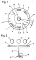
- the die plate 2 is part of a high-performance tableting machine, which is designed as a so-called double rotary machine and has two main printing stations 8 and 8 ', which pre-printing stations 7 and 7' are upstream. Relative to the direction of rotation of the die plate counterclockwise according to arrow 6 are located behind the two main printing stations Sorting switches 10 and 10 ', which are to be moved according to the double arrow 11, if one Bad tablet should be excreted.
- switches 10 and 10 ' Apart from this mobility of the switches 10 and 10 'are the pre-printing stations 7, 7 'and main printing stations 8 and 8' and sorting switches 10 and 10 'are arranged in a fixed position, while the die plate 2 with the die holes 5 and the punches 4 rotate during operation.
- a single tablet For the production of a single tablet, its powder is first passed through in a die hole 5 Pressure rollers 12 or 12 'pre-pressed in a pre-printing station 7 or 7' and then under maximum pressing force with pressure rollers 13 in a main printing station 8 or 8 'pressed.
- the pressing forces used for this will be measured continuously using strain gauges at a measuring point 28 (FIG. 7).
- the measuring point 28 is an amplifier 30 connected downstream, the signals via an analog-digital converter 32 to a Computer 34 transmits, which is designed as a pressure force monitoring device and therefore by electronic Processing compares the received force force signals with setpoint limits.
- a control device 38 for a sorting switch 10 can be activated in order to have a bad tablet to eliminate them.
- an angle pulse generator 20 is provided for their location, which interacts with a coded disk, which acts as a signal generator, for example with a line marking is provided, by means of which, for example, 3,600 pulses during one revolution of the die plate are triggered so that 150 stamps on each stamp in a passage through a main press station omitted.
- the signal disk 18 is arranged on the drive shaft 18 of the die plate 2, so that it with however, each revolution of a die plate rotates once, regardless of its special nature the die plate, that is to say is effective regardless of which stamp division for the die plate is provided.
- the signal disc is provided with a marking that triggers only one pulse with each revolution, the can be referred to as a circumferential pulse or a circulating pulse 22, it is then expedient for this pulse trigger when the marker passes through the starting position zero, that is, at the time, to which a maximum pressing force is exerted on the main station 8 by a punch.
- a circumferential pulse or a circulating pulse 22 A the corresponding representation can be found in FIG. 4, in the upper diagram of the pressure force curve for the Stamps S1, S2 and S3 are reproduced and below the representation is reproduced for the circumferential pulse 22, the switching edge 23 below the maximum pressing force of the punch S1 corresponding to line 40 lies.
- curve (1) shows the pressure force curve at the pre-printing station 7 and curve (2) the pressure force curve at the main pressure station 8, in each case over time (t), so that it can be seen that the maximum pressing force of the punch S1 is measured at the main printing station 8 at a later point in time was when at the pre-printing station 7.
- the maximum of the pressing force of the punch S1 is corresponding to the Curve 2 on the zero line 40, on which the switching edge 23 of the circulation pulse 22 by corresponding Setting the signal disc 18 is.
- the pulse chains with curves 4 and 5, which with mit 1 and ⁇ 2 are designated and can be assigned to the main printing station 8 and the pre-printing station 7.
- Pulse chains or the curves (4, 5) are those pulses that are generated directly by the pulse generator 20 are entered into a first computer 28 (FIG. 7) in accordance with the representation according to FIG. 6.
- the computer 26 converts the signals into output signals according to curves 6 and 7 for the pre-pressure - And main printing station, at which the pulses are at a distance from each other, which is the stamp division ⁇ corresponds to S1, which is entered for curves 2, 3, 4 and 5.
- the pulses corresponding to curves 6 and 7 are parallel to the measured pressing forces in the entered second computer 34 via the analog-digital converter 32, so that a Query of the form as well as the main pressure of individual stamps is made possible and that in double rotary machines also taking into account the second press station and beyond a control the sorting switch 10 and an output of the results in the manner of documents or via a display 36 is possible.
Landscapes
- Engineering & Computer Science (AREA)
- Mechanical Engineering (AREA)
- Medical Preparation Storing Or Oral Administration Devices (AREA)
- Processing And Handling Of Plastics And Other Materials For Molding In General (AREA)
- Presses And Accessory Devices Thereof (AREA)
Claims (6)
- Procédé de surveillance des forces de compression maximales des poinçons (4) d'une machine de production de comprimés coopérant avec un disque de matrices rotatif (2),dans lequel un dispositif d'éjection (10, 10') est à commander par l'intermédiare d'un ordinateur (26, 34) ;dans lequel les forces de compression exercées par les poinçons (4) sont mesurées et entrées dans l'ordinateur (26, 34) ; dans lequel, pour la détermination en continu de la position du disque de matrices (2), on utilise un générateur d'impulsions angulaires (20) coopérant avec un transmetteur de signaux (18) codé couplé de façon réglable à l'arbre d'entraínement (16) du disque de matrices (2), le générateur d'impulsions angulaires (20) déclenchant à chaque rotation du disque de matrices une impulsion séparée de rotation (22) qui est transmise à l'ordinateur (26, 34) connecté au générateur d'impulsions angulaires (20) ; dans lequel le transmetteur de signaux (18) codé est réglé de manière à déclencher l'impulsion de rotation (22) lorsque la force de compression d'un poinçon (4) donné a atteint la valeur maximale ; dans lequel le générateur d'impulsions angulaires (20) génère au moins un train d'impulsions continu (figure 5 : ϕ1 ou ϕ2) et la transmet à l'ordinateur (26, 34) ; et dans lequel l'ordinateur transforme les impulsions reçues en d'autres trains d'impulsions (figure 5 : (6) ou (7)), dont les impulsions présentent une distance les unes par rapport aux autres qui correspond à la distances des poinçons (4), et coordonne des dernières impulsions avec les valeurs de force de compression maximales entrées, de manière à ce que l'ordinateur (26, 34) détermine des écarts type de la force de compression pour émettre des analyses pour la détermination de la qualité de production de chaque comprimé, et transmet au dispositif d'éjection (10, 10') un signal d'éjection se la force de compression mesurée pour un poinçon (4) se situe à l'extérieur de limites de valeurs de consigne.
- Procédé selon la revendication 1, caractérisé en ce qu'avec le générateur d'impulsions angulaires (20) des impulsions séparées pour deux ou plusieurs stations de compression (7, 7', 8, 8') sont données à un ordinateur (26, 34).
- Procédé selon la revendication 1, caractérisé en ce que l'ordinateur (34) commande un aiguillage d'élimination (10) derrière la station de pression principale (8, 8').
- Procédé selon la revendication 1, caractérisé en ce que le générateur d'impulsions angulaires (20) est orienté de manière à ce que l'impulsion de rotation (22) soit générée dans une station de pression principale (8).
- Machine de production de comprimés avec un disque de matrices rotatif (2) entrainé par un arbre d'entraínement et comprenant des poinçons (4) associés aux matrices du disque de matrices (2) ; avec un dispositif d'éjection (10, 10') associé au disque de matrices (2) et avec un ordinateur (26, 34) qui commande le dispositif d'éjection (10, 10') ; avec un dispositif de mesure (28, 30) que mesure les forces de compression exercées par les poinçons (4) et dont les signaux de mesure sont transmis à l'ordinateur (26, 34) ; avec un générateur d'impulsions angulaires (20) pour la détermination en continu de la position du disque de matrices (2), qui coopère avec un transmetteur de signaux (18) codé couplé de façon réglable à l'arbre d'entraínement (16) du disque de matrices (2) ; le générateur d'impulsions angulaires (20) déclenchant à chaque rotation du disque de matrices une impulsion séparée de rotation (22), qui est transmise à l'ordinateur (26, 34) connecté au générateur d'impulsions angulaires (20) ; le transmetteur de signaux codé (18) pouvant être réglé de manière à déclencher l'impulsion de rotation (22) lorsque la force de compression d'un poinçon donné (4) a atteint la valeur maximale ; le générateur d'impulsions angulaires (20) générant au moins un train d'impulsions continu (figure 5 : ϕ1 ou ϕ2) et la transmet tant à l'ordinateur ; et l'ordinateur transformant les impulsions reçues en d'autres trains d'impulsions (figure 5 : (6) ou (7)), dont les impulsions présentent une distance les unes par rapport aux autres qui correspond à la distance des poinçons (4), et coordonnant ces dernières impulsions avec les valeurs de force de compression maximales entrées, de manière à ce que l'ordinateur (26, 34) détermine des écarts type de la force de compression pour émettre des analyses pour la détermination de la qualité de production de chaque comprimé, et transmet au dispositif d'éjection (10, 10') un signal d'éjection si la force de compression mesurée pour un poinçon (4) se situe à l'extérieur de limites de valeurs de consigne.
- Machine de projection de comprimés selon la revendication 5, caractérisée en ce que le transmetteur de signaux (18) présente la forme d'un disque pourvu d'un codage.
Applications Claiming Priority (2)
| Application Number | Priority Date | Filing Date | Title |
|---|---|---|---|
| DE3939956A DE3939956A1 (de) | 1989-12-02 | 1989-12-02 | Verfahren und einrichtung zum ueberwachen der presskraefte einer tablettiermaschine |
| DE3939956 | 1989-12-02 |
Publications (3)
| Publication Number | Publication Date |
|---|---|
| EP0431269A1 EP0431269A1 (fr) | 1991-06-12 |
| EP0431269B1 EP0431269B1 (fr) | 1993-08-11 |
| EP0431269B2 true EP0431269B2 (fr) | 1998-11-04 |
Family
ID=6394714
Family Applications (1)
| Application Number | Title | Priority Date | Filing Date |
|---|---|---|---|
| EP90117988A Expired - Lifetime EP0431269B2 (fr) | 1989-12-02 | 1990-09-19 | Procédé et dispositif de surveillance des forces de compression d'une machine de production des comprimés |
Country Status (3)
| Country | Link |
|---|---|
| US (1) | US5145693A (fr) |
| EP (1) | EP0431269B2 (fr) |
| DE (2) | DE3939956A1 (fr) |
Cited By (2)
| Publication number | Priority date | Publication date | Assignee | Title |
|---|---|---|---|---|
| DE102004008321B3 (de) * | 2004-02-20 | 2005-11-17 | Fette Gmbh | Verfahren und Vorrichtung zur Qualitätsüberwachung bei der Herstellung von Tabletten |
| DE102006002359B4 (de) * | 2006-01-18 | 2009-01-02 | Fette Gmbh | Vorrichtung und Verfahren zur Überwachung der Produktion von Tabletten in einer Rundläuferpresse |
Families Citing this family (18)
| Publication number | Priority date | Publication date | Assignee | Title |
|---|---|---|---|---|
| US5330340A (en) * | 1992-03-25 | 1994-07-19 | The Black Clawson Company | Pelletizer with automatic knife adjustment |
| JPH0780076B2 (ja) * | 1992-04-28 | 1995-08-30 | 株式会社菊水製作所 | 回転式錠剤機の取着ロードセル点検方法 |
| US5322655A (en) * | 1993-02-19 | 1994-06-21 | Thomas Engineering, Inc. | Method for monitoring and controlling the weights of each layer of a multilayer tablet |
| DE19502596C2 (de) * | 1995-01-28 | 1997-08-28 | Fette Wilhelm Gmbh | Meßgerät und Rechner zur Überprüfung der auf einer Rundläuferpresse hergestellten Tabletten der laufenden Produktion |
| US5838571A (en) * | 1996-01-29 | 1998-11-17 | Alza Corporation | Tablet press monitoring and controlling method and apparatus |
| DE19844390B4 (de) | 1998-09-28 | 2005-09-22 | Wilhelm Fette Gmbh | Verfahren zur Herstellung von Tabletten in einer Rundläufertablettiermaschine |
| DE19911294C1 (de) * | 1999-03-13 | 2000-06-15 | Fette Wilhelm Gmbh | Einstellverfahren für eine Rundläufertablettenpresse mit einem Winkelimpulsgeber zur Ermittlung des Preßkraftverlaufs an den einzelnen Stempeln in mindestens einer Preßstation |
| USH2090H1 (en) * | 1999-12-13 | 2003-11-04 | Sherwood Services, A.G. | One-piece unitary occluder |
| DE10113414C2 (de) * | 2001-03-20 | 2003-04-24 | Fette Wilhelm Gmbh | Vorrichtung zum Aussortieren von Tabletten in einer Rundläufer-Tablettenpresse |
| US6854028B2 (en) * | 2001-03-29 | 2005-02-08 | International Business Machines Corporation | Disk drive control for improving the operation of a computer subjected to motion |
| EP1340612A1 (fr) * | 2002-02-14 | 2003-09-03 | Cofmo Preeses | Presse avec un codeur boíte à cames programmable |
| DE102004008322B4 (de) * | 2004-02-20 | 2008-11-27 | Fette Gmbh | Pulverpresse |
| DE102005005012B4 (de) * | 2005-02-03 | 2007-07-05 | Fette Gmbh | Verfahren und Vorrichtung zur Sortierung von Tabletten an einer Rundläufer-Tablettenpresse |
| DE102005007790B4 (de) * | 2005-02-19 | 2007-06-28 | Fette Gmbh | Verfahren und Vorrichtung zur Versuchspressung von Mehrschichttabletten oder Manteltabletten |
| EP1810819B1 (fr) * | 2006-01-18 | 2012-06-13 | Fette GmbH | Presse rotative et procédé destinés à la surveillance de la production de tablettes dans une presse rotative |
| WO2008016183A1 (fr) * | 2006-08-04 | 2008-02-07 | Brother Kogyo Kabushiki Kaisha | Appareil de formation d'image |
| DE102007052552B4 (de) | 2007-10-29 | 2010-01-07 | Luxner, Peter, Dipl.-Ing. | Verfahren und Vorrichtung zur Ermittlung von Steuer- und Regelparametern für Tablettenpressen |
| FR3094656B1 (fr) | 2019-04-03 | 2022-01-07 | Safran Aircraft Engines | Outil de brochage, machine de brochage comportant un tel outil et procédé d’usinage d’une pièce au moyen d’une telle machine |
Family Cites Families (17)
| Publication number | Priority date | Publication date | Assignee | Title |
|---|---|---|---|---|
| DE1958393A1 (de) * | 1969-11-21 | 1971-06-09 | Heidenhain Gmbh Dr Johannes | Vorrichtung zur Winkeleinstellung |
| DE2520662C3 (de) * | 1975-05-09 | 1983-11-03 | Wilhelm Fette Gmbh, 2053 Schwarzenbek | Einrichtung zum Überwachen der Preßkräfte der Stempel einer Tablettenpresse |
| GB1551954A (en) * | 1975-05-28 | 1979-09-05 | Hoffmann La Roche | Standardization of a physiochemical parameter of a batch of formulation in tabletted form |
| AT337532B (de) * | 1975-06-25 | 1977-07-11 | Leinweber Anstalt Ing Joh | Vorrichtung zur optoelektronischen ubertragung von stellsignalen von einem feststehenden teil einer arbeitsmaschine an vorrichtungen bei taktweise weiterdrehenden rundtischen |
| US4100598A (en) * | 1975-09-05 | 1978-07-11 | Hoffmann-La Roche Inc. | Tablet press related instrumentation for use in development and control of formulations of pharmaceutical granulations |
| US4030868A (en) * | 1976-03-15 | 1977-06-21 | Hoffmann-La Roche Inc. | Force measurement and analysis particularly relating to rotary tablet presses |
| DE2824547A1 (de) * | 1978-06-05 | 1979-12-13 | Fette Wilhelm Gmbh | Verfahren und einrichtung zum aussortieren von tabletten nach ihrer herstellung in einer tablettiermaschine |
| US4253811A (en) * | 1979-07-13 | 1981-03-03 | Firma Wilhelm Fette Gmbh | Method of and a device for sorting pellets upon their molding in a preforming press |
| JPS5829600A (ja) * | 1981-08-12 | 1983-02-21 | 株式会社 アマダ | マイクロコンピユ−タによるプレスの制御装置 |
| DE3241063A1 (de) * | 1982-11-06 | 1984-05-10 | Siegfried Ing.(grad.) 7321 Börtlingen Schwarz | Verfahren und einrichtung zur ueberwachung der kraefte an stanzpressen o. dgl. |
| US4570229A (en) * | 1983-09-19 | 1986-02-11 | Pennwalt Corporation | Tablet press controller and method |
| US4606205A (en) * | 1984-11-09 | 1986-08-19 | Continental Can Company, Inc. | Applied force monitor for apparatus for forming products from sheet material |
| US4817006A (en) * | 1986-03-28 | 1989-03-28 | Thomas Engineering, Inc. | Pharmaceutical tablet press control mechanism |
| JPS6310036A (ja) * | 1986-06-30 | 1988-01-16 | Asahi Okuma Ind Co Ltd | パ−ツホ−マ− |
| DE8801566U1 (de) * | 1987-10-22 | 1988-06-01 | ELBEK-Elektroautomation GmbH, 5900 Siegen | Gerät zur Sicherung von Werkzeugen an Stanzen und Pressen |
| DE3735677A1 (de) * | 1987-10-22 | 1989-05-03 | Hohner Elektrotechnik Kg | Drehsignalgeber |
| IT1221567B (it) * | 1987-12-30 | 1990-07-12 | Ima Spa | Macchina comprimitrice per la realizzazione di compresse |
-
1989
- 1989-12-02 DE DE3939956A patent/DE3939956A1/de not_active Withdrawn
-
1990
- 1990-09-19 EP EP90117988A patent/EP0431269B2/fr not_active Expired - Lifetime
- 1990-09-19 DE DE9090117988T patent/DE59002304D1/de not_active Expired - Fee Related
- 1990-11-08 US US07/611,176 patent/US5145693A/en not_active Expired - Lifetime
Cited By (4)
| Publication number | Priority date | Publication date | Assignee | Title |
|---|---|---|---|---|
| DE102004008321B3 (de) * | 2004-02-20 | 2005-11-17 | Fette Gmbh | Verfahren und Vorrichtung zur Qualitätsüberwachung bei der Herstellung von Tabletten |
| US7981352B2 (en) | 2004-02-20 | 2011-07-19 | Fette Gmbh | Method and apparatus for quality surveillance during the manufacture of tablets |
| DE102006002359B4 (de) * | 2006-01-18 | 2009-01-02 | Fette Gmbh | Vorrichtung und Verfahren zur Überwachung der Produktion von Tabletten in einer Rundläuferpresse |
| US7713469B2 (en) | 2006-01-18 | 2010-05-11 | Fette Gmbh | Device and method for monitoring the production of tablets in a rotary press |
Also Published As
| Publication number | Publication date |
|---|---|
| US5145693A (en) | 1992-09-08 |
| DE3939956A1 (de) | 1991-06-06 |
| EP0431269B1 (fr) | 1993-08-11 |
| EP0431269A1 (fr) | 1991-06-12 |
| DE59002304D1 (de) | 1993-09-16 |
Similar Documents
| Publication | Publication Date | Title |
|---|---|---|
| EP0431269B2 (fr) | Procédé et dispositif de surveillance des forces de compression d'une machine de production des comprimés | |
| DE2520662C3 (de) | Einrichtung zum Überwachen der Preßkräfte der Stempel einer Tablettenpresse | |
| DE69612172T2 (de) | Vorrichtung zum Herstellen von Kaffeefiltertabletten für Espresso-Maschinen,ausgehend von einem Folienmaterial | |
| EP1693182B1 (fr) | Procédé et dispositif pour le pressage d'essai de comprimés multi-couches ou de comprimés enrobés | |
| EP0155380A1 (fr) | Ponceuse à bande | |
| DE2600680A1 (de) | Verfahren zur steuerung des betriebsablaufs von werkzeugmaschinen und einrichtung zur durchfuehrung des verfahrens | |
| EP3475027B1 (fr) | Installation d'usinage d'éléments formant flans circulaires | |
| EP0204266B1 (fr) | Presse à tablettes | |
| DE19502596C2 (de) | Meßgerät und Rechner zur Überprüfung der auf einer Rundläuferpresse hergestellten Tabletten der laufenden Produktion | |
| DE102008015820B4 (de) | Vorrichtung und Verfahren zur Messung der vertikalen Position von Ober- und Unterstempeln einer Rundläufer-Tablettenpresse | |
| DE2832982A1 (de) | Positionierungsvorrichtung | |
| DE202018006065U1 (de) | Rundläufer-Tablettenpresse sowie Tablettenablauf hierfür | |
| AT389847B (de) | Elektronisch gesteuerte auswerfvorrichtung fuer fehlerhafte presslinge von einer tablettenpresse mit einem matrizendrehtisch | |
| DE69003581T2 (de) | Pelletpresse. | |
| EP0620108A1 (fr) | Ensemble de poinçons pour une machine de fabrication de comprimés | |
| EP0698481A1 (fr) | Procédé de commande floue pour assurer la qualité dans la fabrication de comprimés | |
| DE1752760A1 (de) | Einrichtung zur Tablettengewichtsueberwachung an Tablettiermaschinen | |
| EP1473145B1 (fr) | Procédé pour le pressage d'essai de comprimés | |
| DE3823417A1 (de) | Verfahren und einrichtung zum ueberwachen der presskraefte der stempel einer tablettenpresse | |
| DE29520473U1 (de) | Vorrichtung zur Herstellung von Tabletten | |
| DE102011101286B4 (de) | Rundläuferpresse und Verfahren zum Betreiben einer Rundläuferpresse | |
| DE19911294C1 (de) | Einstellverfahren für eine Rundläufertablettenpresse mit einem Winkelimpulsgeber zur Ermittlung des Preßkraftverlaufs an den einzelnen Stempeln in mindestens einer Preßstation | |
| DE3639918A1 (de) | Vorrichtung zur steuerung und ueberwachung einer rotationstablettierpresse | |
| DE2547439A1 (de) | Werkzeugsicherung, insbesondere fuer eine werkzeugmaschine | |
| DE2044663B2 (de) | Vorrichtung zum Ablesen von Marken auf der Druckform einer Offsetdruckmaschine |
Legal Events
| Date | Code | Title | Description |
|---|---|---|---|
| PUAI | Public reference made under article 153(3) epc to a published international application that has entered the european phase |
Free format text: ORIGINAL CODE: 0009012 |
|
| AK | Designated contracting states |
Kind code of ref document: A1 Designated state(s): BE CH DE FR GB IT LI |
|
| 17P | Request for examination filed |
Effective date: 19910515 |
|
| 17Q | First examination report despatched |
Effective date: 19930122 |
|
| GRAA | (expected) grant |
Free format text: ORIGINAL CODE: 0009210 |
|
| AK | Designated contracting states |
Kind code of ref document: B1 Designated state(s): BE CH DE FR GB IT LI |
|
| REF | Corresponds to: |
Ref document number: 59002304 Country of ref document: DE Date of ref document: 19930916 |
|
| ITF | It: translation for a ep patent filed | ||
| GBT | Gb: translation of ep patent filed (gb section 77(6)(a)/1977) |
Effective date: 19931001 |
|
| ET | Fr: translation filed | ||
| PLBI | Opposition filed |
Free format text: ORIGINAL CODE: 0009260 |
|
| 26 | Opposition filed |
Opponent name: KORSCH PRESSEN GMBH Effective date: 19940507 |
|
| APAE | Appeal reference modified |
Free format text: ORIGINAL CODE: EPIDOS REFNO |
|
| APCC | Communication from the board of appeal sent |
Free format text: ORIGINAL CODE: EPIDOS OBAPO |
|
| APCC | Communication from the board of appeal sent |
Free format text: ORIGINAL CODE: EPIDOS OBAPO |
|
| APAC | Appeal dossier modified |
Free format text: ORIGINAL CODE: EPIDOS NOAPO |
|
| PLAW | Interlocutory decision in opposition |
Free format text: ORIGINAL CODE: EPIDOS IDOP |
|
| PLAW | Interlocutory decision in opposition |
Free format text: ORIGINAL CODE: EPIDOS IDOP |
|
| PUAH | Patent maintained in amended form |
Free format text: ORIGINAL CODE: 0009272 |
|
| STAA | Information on the status of an ep patent application or granted ep patent |
Free format text: STATUS: PATENT MAINTAINED AS AMENDED |
|
| 27A | Patent maintained in amended form |
Effective date: 19981104 |
|
| AK | Designated contracting states |
Kind code of ref document: B2 Designated state(s): BE CH DE FR GB IT LI |
|
| REG | Reference to a national code |
Ref country code: CH Ref legal event code: AEN Free format text: AUFRECHTERHALTUNG DES PATENTES IN GEAENDERTER FORM |
|
| ITF | It: translation for a ep patent filed | ||
| ET3 | Fr: translation filed ** decision concerning opposition | ||
| GBTA | Gb: translation of amended ep patent filed (gb section 77(6)(b)/1977) | ||
| REG | Reference to a national code |
Ref country code: GB Ref legal event code: IF02 |
|
| APAH | Appeal reference modified |
Free format text: ORIGINAL CODE: EPIDOSCREFNO |
|
| PGFP | Annual fee paid to national office [announced via postgrant information from national office to epo] |
Ref country code: CH Payment date: 20080818 Year of fee payment: 19 |
|
| PGFP | Annual fee paid to national office [announced via postgrant information from national office to epo] |
Ref country code: IT Payment date: 20080827 Year of fee payment: 19 Ref country code: FR Payment date: 20080915 Year of fee payment: 19 |
|
| PGFP | Annual fee paid to national office [announced via postgrant information from national office to epo] |
Ref country code: GB Payment date: 20080924 Year of fee payment: 19 |
|
| PGFP | Annual fee paid to national office [announced via postgrant information from national office to epo] |
Ref country code: DE Payment date: 20080731 Year of fee payment: 19 |
|
| PGFP | Annual fee paid to national office [announced via postgrant information from national office to epo] |
Ref country code: BE Payment date: 20080901 Year of fee payment: 19 |
|
| BERE | Be: lapsed |
Owner name: WILHELM *FETTE G.M.B.H. Effective date: 20090930 |
|
| REG | Reference to a national code |
Ref country code: CH Ref legal event code: PL |
|
| GBPC | Gb: european patent ceased through non-payment of renewal fee |
Effective date: 20090919 |
|
| REG | Reference to a national code |
Ref country code: FR Ref legal event code: ST Effective date: 20100531 |
|
| PG25 | Lapsed in a contracting state [announced via postgrant information from national office to epo] |
Ref country code: DE Free format text: LAPSE BECAUSE OF NON-PAYMENT OF DUE FEES Effective date: 20100401 Ref country code: FR Free format text: LAPSE BECAUSE OF NON-PAYMENT OF DUE FEES Effective date: 20090930 |
|
| PG25 | Lapsed in a contracting state [announced via postgrant information from national office to epo] |
Ref country code: BE Free format text: LAPSE BECAUSE OF NON-PAYMENT OF DUE FEES Effective date: 20090930 |
|
| PG25 | Lapsed in a contracting state [announced via postgrant information from national office to epo] |
Ref country code: LI Free format text: LAPSE BECAUSE OF NON-PAYMENT OF DUE FEES Effective date: 20090930 Ref country code: CH Free format text: LAPSE BECAUSE OF NON-PAYMENT OF DUE FEES Effective date: 20090930 |
|
| PG25 | Lapsed in a contracting state [announced via postgrant information from national office to epo] |
Ref country code: GB Free format text: LAPSE BECAUSE OF NON-PAYMENT OF DUE FEES Effective date: 20090919 |
|
| PG25 | Lapsed in a contracting state [announced via postgrant information from national office to epo] |
Ref country code: IT Free format text: LAPSE BECAUSE OF NON-PAYMENT OF DUE FEES Effective date: 20090919 |