EP0431459A1 - Assemblage de vanne à trois voies avec une vanne d'équilibrage - Google Patents
Assemblage de vanne à trois voies avec une vanne d'équilibrage Download PDFInfo
- Publication number
- EP0431459A1 EP0431459A1 EP90122754A EP90122754A EP0431459A1 EP 0431459 A1 EP0431459 A1 EP 0431459A1 EP 90122754 A EP90122754 A EP 90122754A EP 90122754 A EP90122754 A EP 90122754A EP 0431459 A1 EP0431459 A1 EP 0431459A1
- Authority
- EP
- European Patent Office
- Prior art keywords
- pressure
- port
- housing
- valve
- end surface
- Prior art date
- Legal status (The legal status is an assumption and is not a legal conclusion. Google has not performed a legal analysis and makes no representation as to the accuracy of the status listed.)
- Granted
Links
Images


Classifications
-
- F—MECHANICAL ENGINEERING; LIGHTING; HEATING; WEAPONS; BLASTING
- F16—ENGINEERING ELEMENTS AND UNITS; GENERAL MEASURES FOR PRODUCING AND MAINTAINING EFFECTIVE FUNCTIONING OF MACHINES OR INSTALLATIONS; THERMAL INSULATION IN GENERAL
- F16K—VALVES; TAPS; COCKS; ACTUATING-FLOATS; DEVICES FOR VENTING OR AERATING
- F16K27/00—Construction of housing; Use of materials therefor
-
- F—MECHANICAL ENGINEERING; LIGHTING; HEATING; WEAPONS; BLASTING
- F15—FLUID-PRESSURE ACTUATORS; HYDRAULICS OR PNEUMATICS IN GENERAL
- F15B—SYSTEMS ACTING BY MEANS OF FLUIDS IN GENERAL; FLUID-PRESSURE ACTUATORS, e.g. SERVOMOTORS; DETAILS OF FLUID-PRESSURE SYSTEMS, NOT OTHERWISE PROVIDED FOR
- F15B13/00—Details of servomotor systems ; Valves for servomotor systems
- F15B13/02—Fluid distribution or supply devices characterised by their adaptation to the control of servomotors
- F15B13/06—Fluid distribution or supply devices characterised by their adaptation to the control of servomotors for use with two or more servomotors
- F15B13/08—Assemblies of units, each for the control of a single servomotor only
- F15B13/0803—Modular units
- F15B13/0821—Attachment or sealing of modular units to each other
-
- F—MECHANICAL ENGINEERING; LIGHTING; HEATING; WEAPONS; BLASTING
- F15—FLUID-PRESSURE ACTUATORS; HYDRAULICS OR PNEUMATICS IN GENERAL
- F15B—SYSTEMS ACTING BY MEANS OF FLUIDS IN GENERAL; FLUID-PRESSURE ACTUATORS, e.g. SERVOMOTORS; DETAILS OF FLUID-PRESSURE SYSTEMS, NOT OTHERWISE PROVIDED FOR
- F15B13/00—Details of servomotor systems ; Valves for servomotor systems
- F15B13/02—Fluid distribution or supply devices characterised by their adaptation to the control of servomotors
- F15B13/04—Fluid distribution or supply devices characterised by their adaptation to the control of servomotors for use with a single servomotor
- F15B13/0401—Valve members; Fluid interconnections therefor
- F15B13/0405—Valve members; Fluid interconnections therefor for seat valves, i.e. poppet valves
-
- F—MECHANICAL ENGINEERING; LIGHTING; HEATING; WEAPONS; BLASTING
- F15—FLUID-PRESSURE ACTUATORS; HYDRAULICS OR PNEUMATICS IN GENERAL
- F15B—SYSTEMS ACTING BY MEANS OF FLUIDS IN GENERAL; FLUID-PRESSURE ACTUATORS, e.g. SERVOMOTORS; DETAILS OF FLUID-PRESSURE SYSTEMS, NOT OTHERWISE PROVIDED FOR
- F15B13/00—Details of servomotor systems ; Valves for servomotor systems
- F15B13/02—Fluid distribution or supply devices characterised by their adaptation to the control of servomotors
- F15B13/06—Fluid distribution or supply devices characterised by their adaptation to the control of servomotors for use with two or more servomotors
- F15B13/08—Assemblies of units, each for the control of a single servomotor only
- F15B13/0803—Modular units
- F15B13/0832—Modular valves
- F15B13/0839—Stacked plate type valves
-
- F—MECHANICAL ENGINEERING; LIGHTING; HEATING; WEAPONS; BLASTING
- F15—FLUID-PRESSURE ACTUATORS; HYDRAULICS OR PNEUMATICS IN GENERAL
- F15B—SYSTEMS ACTING BY MEANS OF FLUIDS IN GENERAL; FLUID-PRESSURE ACTUATORS, e.g. SERVOMOTORS; DETAILS OF FLUID-PRESSURE SYSTEMS, NOT OTHERWISE PROVIDED FOR
- F15B13/00—Details of servomotor systems ; Valves for servomotor systems
- F15B13/02—Fluid distribution or supply devices characterised by their adaptation to the control of servomotors
- F15B13/06—Fluid distribution or supply devices characterised by their adaptation to the control of servomotors for use with two or more servomotors
- F15B13/08—Assemblies of units, each for the control of a single servomotor only
- F15B13/0803—Modular units
- F15B13/0878—Assembly of modular units
- F15B13/0885—Assembly of modular units using valves combined with other components
- F15B13/0892—Valves combined with fluid components
-
- F—MECHANICAL ENGINEERING; LIGHTING; HEATING; WEAPONS; BLASTING
- F16—ENGINEERING ELEMENTS AND UNITS; GENERAL MEASURES FOR PRODUCING AND MAINTAINING EFFECTIVE FUNCTIONING OF MACHINES OR INSTALLATIONS; THERMAL INSULATION IN GENERAL
- F16K—VALVES; TAPS; COCKS; ACTUATING-FLOATS; DEVICES FOR VENTING OR AERATING
- F16K27/00—Construction of housing; Use of materials therefor
- F16K27/003—Housing formed from a plurality of the same valve elements
-
- Y—GENERAL TAGGING OF NEW TECHNOLOGICAL DEVELOPMENTS; GENERAL TAGGING OF CROSS-SECTIONAL TECHNOLOGIES SPANNING OVER SEVERAL SECTIONS OF THE IPC; TECHNICAL SUBJECTS COVERED BY FORMER USPC CROSS-REFERENCE ART COLLECTIONS [XRACs] AND DIGESTS
- Y10—TECHNICAL SUBJECTS COVERED BY FORMER USPC
- Y10T—TECHNICAL SUBJECTS COVERED BY FORMER US CLASSIFICATION
- Y10T137/00—Fluid handling
- Y10T137/8593—Systems
- Y10T137/87169—Supply and exhaust
- Y10T137/87233—Biased exhaust valve
- Y10T137/87241—Biased closed
-
- Y—GENERAL TAGGING OF NEW TECHNOLOGICAL DEVELOPMENTS; GENERAL TAGGING OF CROSS-SECTIONAL TECHNOLOGIES SPANNING OVER SEVERAL SECTIONS OF THE IPC; TECHNICAL SUBJECTS COVERED BY FORMER USPC CROSS-REFERENCE ART COLLECTIONS [XRACs] AND DIGESTS
- Y10—TECHNICAL SUBJECTS COVERED BY FORMER USPC
- Y10T—TECHNICAL SUBJECTS COVERED BY FORMER US CLASSIFICATION
- Y10T137/00—Fluid handling
- Y10T137/8593—Systems
- Y10T137/877—With flow control means for branched passages
- Y10T137/87885—Sectional block structure
Definitions
- the present invention relates to a three way valve assembly with a pressure compensating valve, and the pressure compensating valve serves to hold an oil pressure within an actuating oil chamber in a hydraulic apparatus at a predetermined pressure by releasing an abnormal pressure raised at a slow speed when the oil pressure within the actuating oil chamber is abnormally increased at the slow speed by a thermal expansion of the pressurized oil and so on.
- a three way valve assembly 201 with a pressure compensating valve is provided with a three way valve 202, a pressure compensating valve 203, left and right paired end plates 204, 205 and assembly bolts 206, 207, having said three way valve 202 and said pressure compensating valve 203 located between the left and right end plates 204, 205 and having tile left and right end plates 204, 205 tightened by means of said assembly bolts 206, 207 toward the central side from left and right sides.
- the three way valve 202 is provided with a first housing 210, a directional changeover valve member 211 and a directional changeover manipulation means 212.
- a pressure port P, a work port A, a return port R and an abnormal pressure relief port M are communicated to a valve chamber 215, the directional changeover valve member 211 is inserted into the valve chamber 215, and the directional changeover valve member 211 is adapted to be manipulated by the directional changeover manipulation means 212 so as to be changed over to a pressure supply position X and to a pressure discharge position.
- the pressure port P and the return port R are opened in the left and the right end surfaces 210a, 210b of the first housing 210, and to the contrary, said work port A is opened in a portion of an upper, lower, front or back external surrounding surface of the first housing 210.
- the pressure compensating valve 203 is constructed by communicating a pressure discharge outlet port 260 to a pressure inlet port 258 through a throttling passage 259a and a relief valve chamber 260 within a second housing 257, a relief valve member 263 is inserted into the relief valve chamber 260, the pressure inlet port 258 is communicated to the work port A of the three way valve 202, and the pressure discharge outlet port 261 is communicated to the return port R of the three way valve 2.
- a pressure supply port S and a pressure discharge port T are opened in the end plates 204, 205, the pressure supply port S is communicated to the pressure port P of the three way valve 202, and the pressure discharge port T is communicated to the return port R of the three way valve 202.
- the second housing 257 of the pressure compensating valve 203 is kept at its left end surface in contact with the right end surface 210b of the first housing 210 of the three way valve 202 so that both the valves 202, 203 are held and fixedly secured between the left and the right end plates 204, 205 by means of the assembly bolts 206, 207.
- the pressure port P of the three way valve 202 and the pressure supply inlet port 121 of the pressure compensating valve 203 are oil-tightly intercommunicated through O-rings 122, 123, 124 respectively.
- the present invention is intended to make a construction for mounting the three way valve and the pressure compensating valve between both the end plates as follows.
- the left and the right end plates are kept in contact with the left and the right end surfaces of the first housing of the three way valve, and the first housing is fixedly secured between these end plates by means of the assembly bolts.
- the second housing of the pressure compensating valve is kept in contact with any one of the upper, the lower, the front and the back end surfaces of the first housing.
- the second housing is fixedly secured to the first housing by a fixing means.
- the end surface of the first housing with which the second housing is kept in contact may be the lower, the front, or the back end surface besides the upper end surface thereof.
- the work port A may be opened in the back, the upper, the lower, the left or the right end surface of the first housing besides the front end surface thereof.
- the three way valve assembly with the pressure compensating valve is constructed by newly assembling the pressure compensating valve to the ready-installed three way valve, since it is not necessary to additionally bore the second housing to provide the bolt holes for the assembly bolts, it is easy to carry out the work for adding the pressure compensating valve.
- the multiplicate three way valve assembly is constructed by arranging a plurality of three way valves and pressure compensating valves side by side in the left and right direction, since the length thereof can be made much shorter in comparison with that in the prior art as shown in Fig. 10, the aforementioned advantages can be further increased.
- the pressure compensating valve can be readily dismounted from the first housing of the three way valve at the time of maintenance without removal of the assembly bolts, the maintenance can be readily performed.
- FIGS 1 through 8 show embodiments of the present invention
- FIG. 1 through 4 show one embodiment
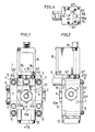
- Figure 1 is an elevation view of a three way valve assembly with a pressure compensating valve
- Figure 2 is a right side view thereof
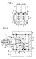
- Figure 3 is a sectional view taken along the III - III directed line in Fig. 1;
- Figure 4 is a sectional view taken along the IV - IV directed line in Fig. 3;
- FIG. 5 through 8 show variants respectively
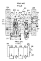
- Figure 5 shows a first variant and is a view corresponding to Fig. 1;
- Figure 6 shows a second variant and is a view corresponding to Fig. 3;
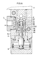
- Figure 7 shows a third variant and is a vertical sectional view of a pressure compensating valve
- Figure 8 shows a fourth variant and is a view corresponding to Fig. 3;
- FIGS 9 and 10 show conventional embodiments
- Figure 9 is a vertical sectional front view of a three way valve assembly with a pressure compensating valve.
- Figure 10 shows a variant and is a view corresponding to Fig. 5.
- a pressure compensating valve 3 is fixedly secured to the upper surface of a three way valve 2, and both these valves 2, 3 are disposed between left and right paired end plates 4, 5. Both the end plates 4, 5 are fixedly tightened to the three way valve 2 by means of two, upper and lower assembly bolts 6, 7 from left and right sides toward central side.
- a pressure switch 8 is fixedly secured to the upper surface of the pressure compensating valve 3.
- the end plates 4, 5 are supported by a stationary table F by means of four attaching bolts 9.
- a valve cover 14 is fixedly secured to the lower portion of a square rod-like first housing 10 in an oil-tight manner by means of threads, and a valve chamber 15 is vertically formed within both the first housing 10 and the valve cover 14.
- a pressure port P is opened in the upper portion of the valve chamber 15.
- the pressure port P is opened in the right end surface 10b of the first housing 10 and is communicated to a pressure supply port S of the right end plate 5.
- This pressure supply port S is connected in communication to a delivery port of a hydraulic pump (not illustrated ).
- a return port R is opened in the lower portion of the valve chamber 15. This return port R is opened in the left end surface 10a of the housing 10, and is communicated to a pressure discharge port T of the left end plate 4.
- This pressure discharge port T is connected in communication to an oil tank (not illustrated ). Further, a work port A is opened in the surrounding wall of the valve chamber 15. This work port A is connected in communication to an actuating oil chamber 18a of a single acting spring return type hydraulic cylinder 18 through a mouthpiece 17 mounted at the front end surface 10e of the first housing 10. A filter 19 is mounted within the mouthpiece 17. Incidentally, the symbol 10f designates a back end surface of the first housing 10.
- valve chamber 15 is vertically partitioned into a first chamber 21 and a second chamber 22 by an intermediate partition wall 20, and these first and second chamber 21, 22 are intercommunicated through a communication port 23.
- a pressure supply valve seat 25 is formed in the first chamber 21 on the side of the pressure supply port P.
- a return valve seat 26 is formed in the second chamber 22 on the side of the return port R.
- a short circuit prevention valve seat 27 is formed in the external periphery of the communication port 23 within the second chamber 22.
- the directional changeover valve member 11 is provided with a check valve member 29 inserted into the first chamber 21 and both a return valve member 32 and a short circuit prevention valve member 33 inserted into the second chamber in order from below.
- the check valve member 29 is resiliently urged onto the pressure supply valve seat 25 by means of a check valve member closing spring 30.
- a valve surface of the check valve member 29 is composed of a rubber elastic sealing member 31.
- the return valve member 32 is vertically oil-tightly inserted into a fitting hole 34 bored in the lower surface of the short circuit prevention valve member 33, through an O-ring 36. Thereby, a received pressure removing chamber 37 is formed between both the valve members 32, 33 in such a manner as being partitioned from the second chamber 22.
- This received pressure removing chamber 37 has its cross-sectional area formed smaller than the opening cross-sectional area of the return valve seat 26 and is communicated to the return port R through a communication port 38 with in the return valve member 32.
- a return valve member closing spring 40 mounted between both the valve member 32, 33, the return valve member 32 is resiliently urged onto the return valve seat 26 as well as the short circuit prevention valve member 33 is resiliently urged onto the short circuit prevention valve seat 27.
- a stopper portion 43 for limiting a downward valve opening movement of the short circuit prevention valve member 33 is formed in the lower side wall of the interior walls of the second chamber 22.
- a stopped portion 44 is downward projected from the short circuit prevention valve member 33 opposite to the stopper portion 43.
- the aforementioned directional changeover manipulation means 12 is disposed outside the lower portion of the valve chamber 15 and is of a pneumatic-actuation single-acting spring-return type. That is, a piston 49 is vertically slidably and air-tightly inserted into a pneumatic cylinder 48 fixedly secured to the lower end surface 10d of the first housing 10. A pneumatic actuation chamber 50 is formed below the piston 49, and a return spring 51 is installed above the piston 49. A valve opening member 53 for the return valve member 32 is formed in the upper portion of a piston rod 52 projected from the upper surface of the piston 49, and the valve opening member 53 is opposed to the return valve member 32 from the side of the return port R.
- the aforementioned three way valve 2 operates as follows.
- a pressurized oil is supplied from the hydraulic pump (not illustrated ) to the pressure port P through the pressure supply port S.
- the check valve member 29 is opened against the valve closing spring 30 by means of an oil pressure at the pressure port P to increase a pressure within the first chamber 21.
- the short circuit prevention valve member 33 is opened against the return valve member closing spring 40 by means of the oil pressure within the first chamber 21.
- the pressurized oil is supplied from the pressure port P to the work port A to extend the hydraulic cylinder 18.
- the return valve member 32 is brought into contact with the return valve seat 26 for valve closing by means of a resultant force of the resilient force of the return valve member closing spring 40 and the inner pressure of the second chamber 22.
- the inner pressure of the second chamber 22 acts on a valve closing pressure receiving area as an annular area obtained by extracting a cross-sectional area of the received pressure removing chamber 37 from the opening cross-sectional area of the return valve seat 26, so that a downward valve closing force is imposed onto the return valve member 32.
- a valve opening movement of the short circuit prevention valve member 33 is limited to a predetermined distance because the stopped portion 44 is adapted to be received by means of the stopper portion 43.
- valve opening member 53 is downward retreated through the piston 49 and the piston rod 52 and changed over to the pressure supply condition.
- a lower end surface 57a as a basic end surface of its second housing 57 is fixedly secured to the upper end surface 10c of the first housing 10 by means of a fixing means 67 composed of four bolts as shown in Figs. 1 and 2.
- the construction of the pressure compensating valve 3 will be explained with reference to Figs. 3 and 4 hereinafter.
- a pressure discharge outlet port 61 is communicated to a pressure inlet port 58 through a throttling valve chamber 59 and a relief valve chamber 60 in order within the second housing 57, and a throttling valve member 62 is inserted into the throttling valve chamber 59 as well as a relief valve member 63 is inserted into the relief valve chamber 60.
- the throttling valve member 62 is internally fitted into the throttling valve chamber 59 so as to be slidable in the left and right direction, and a throttling passage 59a is formed by a gap for sliding between the throttling valve member 62 and the internal surrounding surface of the throttling valve chamber 59.
- a relief valve seat 72 formed at the left end surface of the throttling valve member 62 is capable of advancing and retreating relative to the relief valve chamber 60.
- a receiving surface 73 for the relief valve member 63 is formed at the right end surface of the relief valve chamber 60.
- the relief valve member 63 When a relief pressure adjusting nut 69 is manipulated for such adjustment, the relief valve member 63 is adapted to be pushed toward the throttling valve chamber 59 on the right side by means of the resilient force of the a relief pressure setting spring 70 so that the valve surface 63a can be brought into contact with the relief valve seat 72 for valve closing.
- the pressure inlet port 58 is communicated to the work port A through an abnormal pressure relief port M of the three way valve 2 and the valve chamber 15.
- the pressure discharge outlet port 61 is communicated to the return port R through an abnormal pressure return port N of the three way valve 2.
- a starting end portion 64 of the abnormal pressure return port N and an ending end portion 65 of the abnormal pressure relief port M are opened in the upper end surface 10c of the first housing 10.
- a starting end portion 58a of the pressure inlet port 58 of the pressure compensating valve 3 is communicated to the ending end portion 65 of the abnormal pressure relief port M, and an ending end portion 61b of the pressure discharge outlet port 61 of the pressure compensating valve 3 is communicated to the starting end portion 64 of the abnormal pressure return port N.
- the aforementioned pressure compensating valve 3 operates as follows.
- the relief valve seat 72 is retreated outside the right side of the relief valve chamber 60 by means of a resilient force of a relief pressure setting spring 70 through the valve surface 63a of the relief valve member 63, so that the throttling valve member 62 is pushed and returned to the right side as well as the relief valve member 63 is received by means of the receiving surface 73.
- the throttling valve member 62 is pushed to the left side by means of the high oil pressure, so that the relief valve seat 72 is brought into contact with the valve surface 63a of the relief valve member 63 for valve closing as well as the relief valve seat 72 is entered into the relief valve chamber 60 against the resilient force of the relief pressure setting spring 70.
- the aforementioned pressure switch 8 is fixedly secured to the upper end surface 57b of the second housing 57 of the pressure compensating valve 3 by means of a fixing means 76 composed of two bolts.
- a pressure extraction port 74 communicated to the pressure inlet port 58 with in the second housing 57 and a pressure introduction port 79 of the pressure switch 8 are intercommunicated between the contact surfaces of upper end surface 57b of the second housing 57 and of the pressure switch 8.
- a pressure receiving rod 81 is inserted into a pressure receiving chamber 80 communicated to the pressure introduction port 79 so that the pressure receiving rod 81 can actuate a microswitch (not illustrated ).
- the number of the assembly bolt employed for the left and the right end plates 4, 5 may be not less than three or may be one.
- the upper end surface 10c of the first housing 10 of the three way valve 2 may be located above the upper end surfaces of the left and the right end plates 4, 5. Further, the pressure supply port S and the pressure discharge port T may be provided in only one of the left and the right end plates 4, 5.
- Figs. 5 through 8 show variants respectively.
- a component having the same construction as that in the above embodiment is designated by the same symbol.
- Fig. 5 shows a first variant.
- two sets of three way valves 2 and pressure compensating valves 3 are arranged on the left side and on the right side between the left and right end plates 4, 5. Incidentally, there may be provided not less than three sets of both valves 2, 3.
- Fig. 6 shows a second variant, which modifies the three way valve 2 as follows.
- the directional changeover valve member 11 within the valve chamber 15 is provided with a pressure valve member 93 disposed within the pressure port P and a return valve member 94 disposed within the return port R.
- the pressure valve member 93 and a pressure relief valve member 95 are internally fitted into the return valve member 94, and a valve closing spring 96 is interposed between both these valve members 93, 95.
- a pressure relief valve opening member 98 and a return valve opening member 99 are arranged in the directional changeover manipulation means 12 in order from above so as to be opposed to the pressure relief valve member 95 and the return valve member 94 respectively. Firstly, after the pressure within the valve chamber 15 has been relieved by opening the pressure relief valve member 95, the return valve member 94 is adapted to be opened.
- Fig. 7 shows a third variant, which has the pressure compensating valve 3 modified as follows.
- throttling small screws 84, 85 are threadably engaged with the pressure inlet port 58 so that the throttling passage 59a is constructed by the fitting gap.
- a relief valve member 87 is brought into contact with a relief valve seat 86 fixedly secured to the second housing 57 for valve closing, by means of a relief pressure setting spring 88.
- a resilient force of this setting spring 88 is adapted to be adjusted by means of an adjusting bolt 90 through a piston 89.
- Fig. 8 shows a fourth variant.
- a directional changeover manipulation means 101 of the three way valve 2 is of a manually actuating type and is constructed as follows.
- a pivot shaft 106 is rotatably supported by the lower portion of a bracket 102 fixedly secured to the first housing 10.
- a central portion of the pivot shaft 106 in the left and right direction is reduced in diameter, and a pusher roller 108 is supported by means of a pin 109 at an eccentric position outside the reduced diameter portion 107.
- a pusher tube 111 is inserted into a valve cover 110 so as to be opposed to the pusher roller 108.
- a valve opening manipulation rod 113 is resiliently upward urged by means of a pushing spring 112 within the tubular bore of the pusher tube 111.
- a valve opening member 115 for the return valve member 114 is provided in the upper portion of that rod 113, and the rod 113 is resiliently downward urged by means of a return spring 116.
- This directional changeover manipulation means 101 operates as follows.
Landscapes
- Engineering & Computer Science (AREA)
- General Engineering & Computer Science (AREA)
- Mechanical Engineering (AREA)
- Physics & Mathematics (AREA)
- Fluid Mechanics (AREA)
- Fluid-Pressure Circuits (AREA)
- Valve Housings (AREA)
- Safety Valves (AREA)
- Multiple-Way Valves (AREA)
Applications Claiming Priority (2)
| Application Number | Priority Date | Filing Date | Title |
|---|---|---|---|
| JP1320109A JP2521544B2 (ja) | 1989-12-07 | 1989-12-07 | 油圧装置の圧力保障弁付き三方弁装置 |
| JP320109/89 | 1989-12-07 |
Publications (2)
| Publication Number | Publication Date |
|---|---|
| EP0431459A1 true EP0431459A1 (fr) | 1991-06-12 |
| EP0431459B1 EP0431459B1 (fr) | 1993-07-28 |
Family
ID=18117802
Family Applications (1)
| Application Number | Title | Priority Date | Filing Date |
|---|---|---|---|
| EP90122754A Expired - Lifetime EP0431459B1 (fr) | 1989-12-07 | 1990-11-28 | Assemblage de vanne à trois voies avec une vanne d'équilibrage |
Country Status (5)
| Country | Link |
|---|---|
| US (1) | US5082021A (fr) |
| EP (1) | EP0431459B1 (fr) |
| JP (1) | JP2521544B2 (fr) |
| KR (1) | KR100194273B1 (fr) |
| DE (1) | DE69002444T2 (fr) |
Cited By (1)
| Publication number | Priority date | Publication date | Assignee | Title |
|---|---|---|---|---|
| EP1022471A3 (fr) * | 1999-01-19 | 2002-05-08 | Fleischer Horst | Soupape hydraulique avec insert de soupape et cylindre de soupape |
Families Citing this family (7)
| Publication number | Priority date | Publication date | Assignee | Title |
|---|---|---|---|---|
| US6505639B1 (en) | 1999-12-03 | 2003-01-14 | Ramon Munoz Navarro | Hygienic three way valve |
| US6640685B2 (en) | 2001-02-07 | 2003-11-04 | David M. Hamby | Closed loop electrohydraulic actuator control circuit |
| DE602007011961D1 (de) * | 2006-10-13 | 2011-02-24 | Parker Hannifin Corp | Dreiweg-tellerventil |
| WO2011003584A1 (fr) * | 2009-07-09 | 2011-01-13 | Norgren Gmbh | Système de surveillance de pression à multiples pressostats |
| DE102014008648A1 (de) * | 2014-06-13 | 2015-12-17 | Hydac Technology Gmbh | Anschlussvorrichtung |
| IT201800003266A1 (it) * | 2018-03-05 | 2019-09-05 | Oilcomp S R L | Distributore fluidodinamico |
| JP2022050171A (ja) * | 2020-09-17 | 2022-03-30 | 株式会社コスメック | 圧油給排システム |
Citations (2)
| Publication number | Priority date | Publication date | Assignee | Title |
|---|---|---|---|---|
| US3513876A (en) * | 1968-04-09 | 1970-05-26 | Akro Tec Inc | Valve manifold module and system |
| US4770210A (en) * | 1987-07-23 | 1988-09-13 | Mac Valves, Inc. | Valve manifold stacking base |
Family Cites Families (1)
| Publication number | Priority date | Publication date | Assignee | Title |
|---|---|---|---|---|
| JPS5968801A (ja) * | 1982-10-14 | 1984-04-18 | Canon Electronics Inc | 磁気デイスク装置 |
-
1989
- 1989-12-07 JP JP1320109A patent/JP2521544B2/ja not_active Expired - Lifetime
-
1990
- 1990-11-28 EP EP90122754A patent/EP0431459B1/fr not_active Expired - Lifetime
- 1990-11-28 DE DE90122754T patent/DE69002444T2/de not_active Expired - Fee Related
- 1990-11-30 US US07/619,952 patent/US5082021A/en not_active Expired - Lifetime
- 1990-12-04 KR KR1019900019834A patent/KR100194273B1/ko not_active Expired - Fee Related
Patent Citations (2)
| Publication number | Priority date | Publication date | Assignee | Title |
|---|---|---|---|---|
| US3513876A (en) * | 1968-04-09 | 1970-05-26 | Akro Tec Inc | Valve manifold module and system |
| US4770210A (en) * | 1987-07-23 | 1988-09-13 | Mac Valves, Inc. | Valve manifold stacking base |
Cited By (1)
| Publication number | Priority date | Publication date | Assignee | Title |
|---|---|---|---|---|
| EP1022471A3 (fr) * | 1999-01-19 | 2002-05-08 | Fleischer Horst | Soupape hydraulique avec insert de soupape et cylindre de soupape |
Also Published As
| Publication number | Publication date |
|---|---|
| US5082021A (en) | 1992-01-21 |
| EP0431459B1 (fr) | 1993-07-28 |
| JP2521544B2 (ja) | 1996-08-07 |
| DE69002444T2 (de) | 1993-11-18 |
| KR910012585A (ko) | 1991-08-08 |
| KR100194273B1 (ko) | 1999-06-15 |
| DE69002444D1 (de) | 1993-09-02 |
| JPH03181682A (ja) | 1991-08-07 |
Similar Documents
| Publication | Publication Date | Title |
|---|---|---|
| US6491007B1 (en) | Hydraulically controllable globe valve | |
| EP0283053B1 (fr) | Soupape hydraulique | |
| CA1273328A (fr) | Organe de manoeuvre hydraulique bi-etage pour opercule de vanne | |
| CN100520088C (zh) | 流量控制阀和带有该流量控制阀的缸设备 | |
| EP0431459B1 (fr) | Assemblage de vanne à trois voies avec une vanne d'équilibrage | |
| US20110146814A1 (en) | Elbow plug external sleeve valve | |
| KR950704617A (ko) | 가압유 공급장치(Pressurized fluid supply system) | |
| KR100294363B1 (ko) | 베이스부착형변환밸브에부착하기위한압력조절밸브 | |
| US4554940A (en) | Pressure reducing and regulating valve | |
| US4475568A (en) | Pressure reducing and regulating valve | |
| US5638748A (en) | Hydraulic overload proportional valving system for a mechanical press | |
| US5334003A (en) | Air valving mechanism, in combination with a double diaphragm pump subassembly | |
| EP0972948B1 (fr) | Régulateur de pression pour un agrégat à électrovannes et assemblage d'électrovannes muni avec celui-ci | |
| US2661017A (en) | Pilot operated valve | |
| CA1233091A (fr) | Distributeur a tiroir pour reseau pneumatique | |
| EP0122247B1 (fr) | Valve de commande | |
| US5235896A (en) | Hydraulic cylinder/piston mechanism | |
| US2155257A (en) | Fluid compressor | |
| GB2037630A (en) | Hydraulic drilling machine | |
| GB2226110A (en) | Improvements in valve devices for use in mining | |
| CN212616519U (zh) | 一种组合开关 | |
| JPH05196007A (ja) | 空圧シリンダ用制御装置 | |
| KR100271279B1 (ko) | 유압모터의 시간지연장치 | |
| EP0354013B1 (fr) | Vérin dans une transmission toroidale à friction | |
| RU2092715C1 (ru) | Масляный насос с двойным управлением, ручным и пневматическим |
Legal Events
| Date | Code | Title | Description |
|---|---|---|---|
| PUAI | Public reference made under article 153(3) epc to a published international application that has entered the european phase |
Free format text: ORIGINAL CODE: 0009012 |
|
| 17P | Request for examination filed |
Effective date: 19901205 |
|
| AK | Designated contracting states |
Kind code of ref document: A1 Designated state(s): DE FR GB IT |
|
| 17Q | First examination report despatched |
Effective date: 19921214 |
|
| GRAA | (expected) grant |
Free format text: ORIGINAL CODE: 0009210 |
|
| AK | Designated contracting states |
Kind code of ref document: B1 Designated state(s): DE FR GB IT |
|
| REF | Corresponds to: |
Ref document number: 69002444 Country of ref document: DE Date of ref document: 19930902 |
|
| ITF | It: translation for a ep patent filed | ||
| ET | Fr: translation filed | ||
| PLBE | No opposition filed within time limit |
Free format text: ORIGINAL CODE: 0009261 |
|
| STAA | Information on the status of an ep patent application or granted ep patent |
Free format text: STATUS: NO OPPOSITION FILED WITHIN TIME LIMIT |
|
| 26N | No opposition filed | ||
| K1C1 | Correction of patent application (title page) published |
Effective date: 19910612 |
|
| PGFP | Annual fee paid to national office [announced via postgrant information from national office to epo] |
Ref country code: FR Payment date: 19991109 Year of fee payment: 10 |
|
| PGFP | Annual fee paid to national office [announced via postgrant information from national office to epo] |
Ref country code: GB Payment date: 19991124 Year of fee payment: 10 |
|
| PG25 | Lapsed in a contracting state [announced via postgrant information from national office to epo] |
Ref country code: GB Free format text: LAPSE BECAUSE OF NON-PAYMENT OF DUE FEES Effective date: 20001128 |
|
| GBPC | Gb: european patent ceased through non-payment of renewal fee |
Effective date: 20001128 |
|
| PG25 | Lapsed in a contracting state [announced via postgrant information from national office to epo] |
Ref country code: FR Free format text: LAPSE BECAUSE OF NON-PAYMENT OF DUE FEES Effective date: 20010731 |
|
| REG | Reference to a national code |
Ref country code: FR Ref legal event code: ST |
|
| PGFP | Annual fee paid to national office [announced via postgrant information from national office to epo] |
Ref country code: DE Payment date: 20031103 Year of fee payment: 14 |
|
| PG25 | Lapsed in a contracting state [announced via postgrant information from national office to epo] |
Ref country code: DE Free format text: LAPSE BECAUSE OF NON-PAYMENT OF DUE FEES Effective date: 20050601 |
|
| PG25 | Lapsed in a contracting state [announced via postgrant information from national office to epo] |
Ref country code: IT Free format text: LAPSE BECAUSE OF NON-PAYMENT OF DUE FEES Effective date: 20051128 |