EP0432045A1 - Gittergesteuerte Röhre mit besserem Wirkungsgrad - Google Patents
Gittergesteuerte Röhre mit besserem Wirkungsgrad Download PDFInfo
- Publication number
- EP0432045A1 EP0432045A1 EP90403471A EP90403471A EP0432045A1 EP 0432045 A1 EP0432045 A1 EP 0432045A1 EP 90403471 A EP90403471 A EP 90403471A EP 90403471 A EP90403471 A EP 90403471A EP 0432045 A1 EP0432045 A1 EP 0432045A1
- Authority
- EP
- European Patent Office
- Prior art keywords
- signal
- voltage
- duration
- tube
- class
- Prior art date
- Legal status (The legal status is an assumption and is not a legal conclusion. Google has not performed a legal analysis and makes no representation as to the accuracy of the status listed.)
- Granted
Links
- 230000005540 biological transmission Effects 0.000 abstract description 3
- 230000010287 polarization Effects 0.000 abstract description 3
- 230000003321 amplification Effects 0.000 description 3
- 238000003199 nucleic acid amplification method Methods 0.000 description 3
- 238000010586 diagram Methods 0.000 description 2
- 230000000630 rising effect Effects 0.000 description 2
- 241001080024 Telles Species 0.000 description 1
- 230000007547 defect Effects 0.000 description 1
- 230000000694 effects Effects 0.000 description 1
- 230000001960 triggered effect Effects 0.000 description 1
Images


Classifications
-
- H—ELECTRICITY
- H04—ELECTRIC COMMUNICATION TECHNIQUE
- H04N—PICTORIAL COMMUNICATION, e.g. TELEVISION
- H04N5/00—Details of television systems
- H04N5/38—Transmitter circuitry for the transmission of television signals according to analogue transmission standards
-
- H—ELECTRICITY
- H03—ELECTRONIC CIRCUITRY
- H03F—AMPLIFIERS
- H03F1/00—Details of amplifiers with only discharge tubes, only semiconductor devices or only unspecified devices as amplifying elements
- H03F1/02—Modifications of amplifiers to raise the efficiency, e.g. gliding Class A stages, use of an auxiliary oscillation
- H03F1/04—Modifications of amplifiers to raise the efficiency, e.g. gliding Class A stages, use of an auxiliary oscillation in discharge-tube amplifiers
Definitions
- the present invention relates to tubes with at least one grid, used as amplifiers and which produce signals whose amplitude varies significantly. It aims to improve their performance.
- the tubes used in television transmitters are generally tetrodes.
- the invention can very well be applied to other grid tubes such as triodes, pentodes, etc.
- the amplifier tubes used as television transmitters generally operate in class B.
- the invention can also be applied to amplifier tubes operating in class AB, B or C.
- a triode is a tube comprising a cathode emitting electrons, an anode or plate and a single grid, called the control grid, placed between the cathode and the anode.
- a tetrode has an additional grid called a screen grid, placed between the control grid and the anode.
- a pentode has one more grid than the tetrode, this grid known as the stop grid being inserted between the screen grid and the anode.
- a television transmitter transmits a video signal comprising in particular the repetition of the following two signals: a synchronization signal and a line video signal.
- the repetition period of these two signals is approximately 64 microseconds in 625 line systems.
- the synchronization signal is a pulse substantially rectangular, the duration of which is approximately 4.6 microseconds. This duration is very short compared to the rehearsal period.
- the line video signal lasts the rest of the repeat period, i.e. approximately 59.4 microseconds.
- the maximum power of the transmitter is delivered during the synchronization signal.
- the maximum level of the line video signal corresponds to black
- the minimum level of the line video signal corresponds to white.
- the synchronization signal corresponds to the minimum power of the transmitter.
- the maximum level of the line video signal corresponds to white and the minimum level to black.
- This bias voltage is used only for the duration of the synchronization signal and is unnecessarily high for the duration of the line video signal.
- the efficiency of the tube is proportional to the ratio of the voltage of the video signal emitted by the tube to the bias voltage of the anode. Since the transmission time of the line signal is much longer than the transmission time of the synchronization signal, the overall efficiency of the tube is practically that of the line video signal. And this efficiency is very low because of the unnecessarily high bias voltage.
- the present invention aims to remedy this drawback by proposing a grid tube with improved efficiency. It applies to all amplifier tubes producing at least a combination of a first signal for a short duration and a second signal for a longer duration, the maximum voltage of the first signal being greater than the maximum voltage of the second signal.
- the anode bias voltage is reduced to a level sufficient to obtain the maximum voltage of the second signal.
- the reduced anode bias voltage no longer makes it possible a priori to obtain the maximum voltage of the first signal.
- the gain of the tube then drops during the duration of the first signal which is not desirable.
- the class of the tube is changed to class A for the duration of the first signal.
- the present invention provides a grid amplifier tube comprising an anode and at least one control grid each supplied by a bias voltage, producing with a substantially constant gain, at least a combination of a first signal over a short duration and of a second signal over a longer duration, the maximum voltage of the first signal being greater than the maximum voltage of the second signal, characterized in that: the anode bias voltage is adjusted to a level allowing the tube to operate in class B , AB or C and to produce the maximum voltage of the second signal but not that of the first signal and in that means allow the class of the tube to evolve towards class A during the duration of the first signal so that the tube produces the voltage maximum of the first signal.
- At least one of the bias voltages is varied.
- the tube has a screen grid, it can supply its screen grid with a modulated bias voltage.
- This voltage then comprises a pulse of positive amplitude, the duration of which is that of the first signal.
- This voltage then includes a pulse of positive amplitude, the duration of which is that of the first signal.
- This voltage then comprises a pulse of positive amplitude, the duration of which is that of the first signal.
- the invention is particularly applicable to television transmitters operating in negative modulation and the amplifier tube produces a video signal which is at least a combination of a short duration synchronization signal and a longer duration line video signal. .
- the maximum voltage of the line video signal corresponds to the color black.
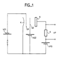
- FIG. 1 The diagram of a conventional tetrode tube mounted as an amplifier is shown in FIG. 1.
- This tube comprises a cathode K intended to emit electrons, a control grid G1 supplied by a bias voltage VG1, a screen grid G2 powered by a bias voltage VG2 and an anode A or plate powered by a bias voltage VPO. Thereafter, a voltage source and the voltage it produces will be designated by the same reference.
- a voltage V is applied to the gate G1 which corresponds to the signal to be amplified.
- a resistor R is mounted between the anode A and the voltage source VPO. At the terminals of this resistance appears a voltage VP which corresponds to the voltage V after amplification.
- the bias voltages are direct voltages.
- the voltage VG1 is negative with respect to the potential of the cathode K.
- the tetrode When the tetrode is used as an amplifier in a television transmitter, it produces a video signal VP comprising in particular the repetition of the following two signals: a synchronization signal and a line video signal.
- the repetition period for these two signals is approximately 64 microseconds.
- the synchronization signal lasts 4.6 microseconds and the line video signal approximately 59.4 microseconds.
- the tube produces at least a combination of a first signal which is the synchronization signal and a second signal which is the line video signal.
- the synchronization signal consists of a substantially rectangular pulse.
- the maximum voltage VP max of the synchronization signal is greater than the maximum voltage VPN of the line video signal.
- the VPN voltage corresponds to the black color.
- FIG. 2 shows the voltages VPO and VP as a function of time.
- the level of the VPN voltage of the black video signal is indicated.
- the voltages VG1, VG2 are shown. The two figures are not on the same scale.
- the voltage VP is such that the ratio VP2 / 2 R is equal to the power that must be output from the transmitter.
- the VPO voltage must be greater than VP.
- the VP / VPO ratio is of the order of 0.8.
- the ratio of the maximum voltage of the VPN line video signal to the voltage of the synchronization signal is of the order of 0.73.
- the tube must operate linearly even at high output power. Otherwise, the non-linearities introduce distortions in the amplitude of the output signal and these non-linearities are very troublesome especially for color video signals.
- the power gain curve of the tube should be as straight as possible. This curve represents the power of the tube output signal as a function of the power of the tube input signal. It can however be assumed that this curve bends a few percent for output powers greater than the power corresponding to the black level.
- the tubes used as television transmitters operate in class B.
- the efficiency of the tube is practically the efficiency for the duration of the line video signal and this efficiency is very low.
- the present invention aims to remedy this drawback.
- the voltage VP1 is naturally lower than the voltage VPO chosen previously.
- the power obtained at the output of the transmitter is then insufficient and a drop in gain and a linearity defect in the tube are observed.
- the fall gain can go up to 10 to 12%, for example.
- FIG. 4 also includes the voltage VP ′ of the video signal which is obtained, when a voltage VP1 lower than VPO is used and the class of the tube has been changed to class A, during the duration of the synchronization signal.
- a voltage VP1 and changing the class of the tube during the duration of the synchronization signal makes it possible to obtain both the maximum voltage VP 'max of the synchronization signal and the maximum voltage VPN' of the video signal of line.
- the pulses have the duration of the synchronization signal duration, they will be substantially rectangular with rising and falling edges as steep as possible. Their amplitude will be positive.
- the bias voltage VG1 of the control gate G1 is not changed.
- bias voltage VG1 of the control gate G1 it is also possible to act on the bias voltage VG1 of the control gate G1 throughout the duration of the synchronization signal. This amounts to modulating the voltage VG1 in pulses.
- the pulses will be substantially rectangular with rising and falling edges as steep as possible. Their amplitude will be positive.
- the bias voltage of the screen grid G2 is not modified.
- an appropriate electronic device triggered by the pulses of the synchronization signal is used.
- the invention is not limited to amplifier tubes used in television transmitters.
Landscapes
- Engineering & Computer Science (AREA)
- Power Engineering (AREA)
- Multimedia (AREA)
- Signal Processing (AREA)
- Amplifiers (AREA)
- Picture Signal Circuits (AREA)
- Making Paper Articles (AREA)
- Vessels And Coating Films For Discharge Lamps (AREA)
- Vaporization, Distillation, Condensation, Sublimation, And Cold Traps (AREA)
- Table Equipment (AREA)
Priority Applications (1)
| Application Number | Priority Date | Filing Date | Title |
|---|---|---|---|
| AT90403471T ATE104098T1 (de) | 1989-12-08 | 1990-12-06 | Gittergesteuerte roehre mit besserem wirkungsgrad. |
Applications Claiming Priority (2)
| Application Number | Priority Date | Filing Date | Title |
|---|---|---|---|
| FR8916266A FR2655790B1 (fr) | 1989-12-08 | 1989-12-08 | Tube a grille a rendement ameliore. |
| FR8916266 | 1989-12-08 |
Publications (2)
| Publication Number | Publication Date |
|---|---|
| EP0432045A1 true EP0432045A1 (de) | 1991-06-12 |
| EP0432045B1 EP0432045B1 (de) | 1994-04-06 |
Family
ID=9388301
Family Applications (1)
| Application Number | Title | Priority Date | Filing Date |
|---|---|---|---|
| EP90403471A Expired - Lifetime EP0432045B1 (de) | 1989-12-08 | 1990-12-06 | Gittergesteuerte Röhre mit besserem Wirkungsgrad |
Country Status (7)
| Country | Link |
|---|---|
| US (1) | US5099332A (de) |
| EP (1) | EP0432045B1 (de) |
| JP (1) | JP3226286B2 (de) |
| AT (1) | ATE104098T1 (de) |
| DE (1) | DE69007950T2 (de) |
| ES (1) | ES2050982T3 (de) |
| FR (1) | FR2655790B1 (de) |
Families Citing this family (2)
| Publication number | Priority date | Publication date | Assignee | Title |
|---|---|---|---|---|
| FR2823618B1 (fr) * | 2001-04-13 | 2003-05-30 | Electricite De France | Etage d'un generateur de puissance d'un courant haute frequence |
| IT1398612B1 (it) * | 2010-03-16 | 2013-03-08 | Parsek S R L | Metodo per regolare la potenza di uscita massima di uno stadio amplificatore di potenza a valvole per un amplificatore audio, e corrispondente stadio amplificatore di potenza a valvole |
Citations (4)
| Publication number | Priority date | Publication date | Assignee | Title |
|---|---|---|---|---|
| GB444050A (en) * | 1934-05-02 | 1936-03-12 | Lorenz C Ag | Improvements in or relating to thermionic valve amplifiers |
| DE747334C (de) * | 1938-03-19 | 1944-12-04 | Lorenz C Ag | Verfahren zur Leistungsersparnis in Hochfrequenzsendern |
| US2500831A (en) * | 1945-08-08 | 1950-03-14 | Hartford Nat Bank & Trust Co | Circuit arrangement for amplifying image signals and synchronizing signals |
| US2881394A (en) * | 1952-12-05 | 1959-04-07 | Soc Nouvelle Outil Rbv Radio | Grid modulating a television transmitter by successive modulation of carrier in plural stages |
Family Cites Families (22)
| Publication number | Priority date | Publication date | Assignee | Title |
|---|---|---|---|---|
| NL56601C (de) * | 1938-03-19 | |||
| US2903585A (en) * | 1957-12-10 | 1959-09-08 | Admiral Corp | Detector circuit |
| US3027519A (en) * | 1959-04-21 | 1962-03-27 | Bendix Corp | Gain-versus-bandwidth control amplifier particularly adapted for television circuitry |
| GB1135828A (en) * | 1965-05-14 | 1968-12-04 | Fernseh Gmbh | Circuit arrangement for controlling the level of a signal |
| US3598906A (en) * | 1968-01-23 | 1971-08-10 | Mitsubishi Electric Corp | Fine tuning indicator |
| US3648179A (en) * | 1968-06-07 | 1972-03-07 | Hitachi Ltd | Control device with a plurality of controlling units which are simply adjustable bath individually and simultaneously to desirable conditions |
| US3598913A (en) * | 1968-12-18 | 1971-08-10 | Philips Corp | Television receiver |
| FR2116725A5 (de) * | 1970-12-04 | 1972-07-21 | Thomson Csf | |
| FR2255697B1 (de) * | 1973-12-21 | 1977-08-12 | Thomson Csf | |
| FR2255698B1 (de) * | 1973-12-21 | 1977-08-19 | Thomson Csf | |
| FR2276681A1 (fr) * | 1974-06-28 | 1976-01-23 | Thomson Csf | Grille pour tube electronique et tube comportant une telle grille |
| FR2298184A1 (fr) * | 1975-01-14 | 1976-08-13 | Thomson Csf | Dispositif de suppression d'oscillations parasites et tube electronique comportant un tel dispositif |
| FR2315764A1 (fr) * | 1975-06-27 | 1977-01-21 | Thomson Csf | Dispositif de prise de vues a cible resistive |
| FR2445037A1 (fr) * | 1978-12-22 | 1980-07-18 | Thomson Csf | Filtre de bande de frequence |
| JPS5767351A (en) * | 1980-10-15 | 1982-04-23 | Nec Corp | Two-way transmission circuit |
| JPS5767381A (en) * | 1980-10-15 | 1982-04-23 | Toshiba Corp | Power amplifier |
| JPS58114510A (ja) * | 1981-12-26 | 1983-07-07 | Nippon Gakki Seizo Kk | 電力増幅器 |
| FR2532468A1 (fr) * | 1982-08-31 | 1984-03-02 | Thomson Csf | Perfectionnement aux cathodes a chauffage direct |
| FR2538612B1 (fr) * | 1982-12-23 | 1985-10-04 | Thomson Csf | Cavites coaxiales resonnantes pour tubes a grilles |
| FR2564240B1 (fr) * | 1984-05-09 | 1986-09-19 | Thomson Csf | Tube electronique muni d'un dispositif de refroidissement de l'embase de grille |
| FR2564239B1 (fr) * | 1984-05-09 | 1986-09-19 | Thomson Csf | Tube electronique muni d'un dispositif de refroidissement de la cathode |
| FR2622067B1 (fr) * | 1987-10-16 | 1991-06-14 | Thomson Csf | Amplificateur haute frequence avec circuit de neutrodynage automatique |
-
1989
- 1989-12-08 FR FR8916266A patent/FR2655790B1/fr not_active Expired - Lifetime
-
1990
- 1990-11-16 US US07/614,126 patent/US5099332A/en not_active Expired - Lifetime
- 1990-12-06 EP EP90403471A patent/EP0432045B1/de not_active Expired - Lifetime
- 1990-12-06 AT AT90403471T patent/ATE104098T1/de not_active IP Right Cessation
- 1990-12-06 ES ES90403471T patent/ES2050982T3/es not_active Expired - Lifetime
- 1990-12-06 DE DE69007950T patent/DE69007950T2/de not_active Expired - Fee Related
- 1990-12-07 JP JP41415790A patent/JP3226286B2/ja not_active Expired - Fee Related
Patent Citations (4)
| Publication number | Priority date | Publication date | Assignee | Title |
|---|---|---|---|---|
| GB444050A (en) * | 1934-05-02 | 1936-03-12 | Lorenz C Ag | Improvements in or relating to thermionic valve amplifiers |
| DE747334C (de) * | 1938-03-19 | 1944-12-04 | Lorenz C Ag | Verfahren zur Leistungsersparnis in Hochfrequenzsendern |
| US2500831A (en) * | 1945-08-08 | 1950-03-14 | Hartford Nat Bank & Trust Co | Circuit arrangement for amplifying image signals and synchronizing signals |
| US2881394A (en) * | 1952-12-05 | 1959-04-07 | Soc Nouvelle Outil Rbv Radio | Grid modulating a television transmitter by successive modulation of carrier in plural stages |
Non-Patent Citations (2)
| Title |
|---|
| PATENT ABSTRACTS OF JAPAN vol. 6, no. 144 (E-122)(1022) 03 août 1982, & JP-A-57 67381 (TOKYO SHIBAURA DENKI K.K.) 23 avril 1982, * |
| PATENT ABSTRACTS OF JAPAN vol. 7, no. 222 (E-201)(1367) 04 septembre 1983, & JP-A-58 114510 (NIPPON GAKKI SEIZO K.K.) 07 juillet 1983, * |
Also Published As
| Publication number | Publication date |
|---|---|
| FR2655790A1 (fr) | 1991-06-14 |
| EP0432045B1 (de) | 1994-04-06 |
| JP3226286B2 (ja) | 2001-11-05 |
| DE69007950D1 (de) | 1994-05-11 |
| DE69007950T2 (de) | 1994-07-21 |
| ES2050982T3 (es) | 1994-06-01 |
| JPH0689668A (ja) | 1994-03-29 |
| ATE104098T1 (de) | 1994-04-15 |
| US5099332A (en) | 1992-03-24 |
| FR2655790B1 (fr) | 1992-01-24 |
Similar Documents
| Publication | Publication Date | Title |
|---|---|---|
| BE1023023B1 (fr) | Systemes et procedes de limitation de retard d'image pour sortie a injection directe tamponnee avec miroir de courant. | |
| FR2529421A1 (fr) | Reglage de l'image d'un televiseur en reponse a la lumiere ambiante, a plusieurs modes de fonctionnement | |
| EP1719102A1 (de) | Einrichtung zur verbesserung der pixeladressierung | |
| EP0432045B1 (de) | Gittergesteuerte Röhre mit besserem Wirkungsgrad | |
| EP0375038B1 (de) | Videobildwiedergabevorrichtung mit einer Kontrastregeleinheit und Verfahren zur Kontrasteinstellung einer solchen Wiedergabevorrichtung | |
| FR2528588A1 (fr) | Procede et dispositif de composition et de recopie d'images electroniques multiples sur une surface photosensible | |
| EP0240395B1 (de) | Verfahren und Vorrichtung zur Gammakorrektur einer mehrfarbigen Kathodenstrahlröhre | |
| FR2473232A1 (fr) | Amplificateur de puissance efficace a tensions d'alimentation decalees | |
| FR2561051A1 (fr) | Systeme de traitement de signaux video avec limiteur automatique des courants des faisceaux | |
| EP2430659A1 (de) | Integrierter hochsensibler bildsensor | |
| EP0540331A2 (de) | Vorrichtung und Verfahren zur Ansteuerung eines Lichtmodulators mit Elektroabsorption | |
| EP3824549B1 (de) | Architektur für hf-funkfrequenzsender | |
| WO2006024739A1 (fr) | Amplificateur audio classe ad | |
| EP4380048A1 (de) | System und verfahren zur betriebsverwaltung eines wanderfeldröhrenverstärkers | |
| EP0711034B1 (de) | Vorrichtung zum Generieren von Übertragungsfunktionen in Segmenten | |
| EP0022412A1 (de) | Verfahren zum automatischen Ausarbeiten und Korrigieren der Sperrspannung einer Elektronenkanone und Vorrichtung zur Durchführung des Verfahrens | |
| FR2547143A1 (de) | ||
| BE662533A (de) | ||
| JPH11304586A (ja) | 光量測定装置および方法 | |
| FR2535550A1 (fr) | Circuit d'echantillonnage de signaux | |
| BE532327A (de) | ||
| FR2853133A1 (fr) | Dispositif et procede de commande et de controle d'une dose d'electrons emise par un micro-emetteur | |
| FR2536937A1 (fr) | Agencement de circuit pour un dispositif analyseur d'image de camera de television en couleurs | |
| FR2711295A1 (fr) | Appareil d'affichage d'images avec modulation de vitesse du spot. | |
| JPH06152026A (ja) | 発光素子の駆動回路 |
Legal Events
| Date | Code | Title | Description |
|---|---|---|---|
| PUAI | Public reference made under article 153(3) epc to a published international application that has entered the european phase |
Free format text: ORIGINAL CODE: 0009012 |
|
| AK | Designated contracting states |
Kind code of ref document: A1 Designated state(s): AT CH DE ES FR GB IT LI NL SE |
|
| 17P | Request for examination filed |
Effective date: 19910706 |
|
| 17Q | First examination report despatched |
Effective date: 19921021 |
|
| GRAA | (expected) grant |
Free format text: ORIGINAL CODE: 0009210 |
|
| AK | Designated contracting states |
Kind code of ref document: B1 Designated state(s): AT CH DE ES FR GB IT LI NL SE |
|
| PG25 | Lapsed in a contracting state [announced via postgrant information from national office to epo] |
Ref country code: SE Free format text: THE PATENT HAS BEEN ANNULLED BY A DECISION OF A NATIONAL AUTHORITY Effective date: 19940406 Ref country code: NL Effective date: 19940406 Ref country code: AT Effective date: 19940406 |
|
| REF | Corresponds to: |
Ref document number: 104098 Country of ref document: AT Date of ref document: 19940415 Kind code of ref document: T |
|
| ITF | It: translation for a ep patent filed | ||
| REF | Corresponds to: |
Ref document number: 69007950 Country of ref document: DE Date of ref document: 19940511 |
|
| REG | Reference to a national code |
Ref country code: ES Ref legal event code: FG2A Ref document number: 2050982 Country of ref document: ES Kind code of ref document: T3 |
|
| GBT | Gb: translation of ep patent filed (gb section 77(6)(a)/1977) |
Effective date: 19940512 |
|
| NLV1 | Nl: lapsed or annulled due to failure to fulfill the requirements of art. 29p and 29m of the patents act | ||
| PG25 | Lapsed in a contracting state [announced via postgrant information from national office to epo] |
Ref country code: LI Effective date: 19941231 Ref country code: CH Effective date: 19941231 |
|
| PLBE | No opposition filed within time limit |
Free format text: ORIGINAL CODE: 0009261 |
|
| STAA | Information on the status of an ep patent application or granted ep patent |
Free format text: STATUS: NO OPPOSITION FILED WITHIN TIME LIMIT |
|
| 26N | No opposition filed | ||
| REG | Reference to a national code |
Ref country code: CH Ref legal event code: PL Ref country code: CH Ref legal event code: AUV Free format text: LE BREVET CI-DESSUS EST TOMBE EN DECHEANCE, FAUTE DE PAIEMENT, DE LA 5E ANNUITE. |
|
| REG | Reference to a national code |
Ref country code: GB Ref legal event code: IF02 |
|
| PGFP | Annual fee paid to national office [announced via postgrant information from national office to epo] |
Ref country code: GB Payment date: 20051130 Year of fee payment: 16 |
|
| PGFP | Annual fee paid to national office [announced via postgrant information from national office to epo] |
Ref country code: DE Payment date: 20051201 Year of fee payment: 16 |
|
| PGFP | Annual fee paid to national office [announced via postgrant information from national office to epo] |
Ref country code: ES Payment date: 20060118 Year of fee payment: 16 |
|
| PGFP | Annual fee paid to national office [announced via postgrant information from national office to epo] |
Ref country code: FR Payment date: 20061208 Year of fee payment: 17 |
|
| PGFP | Annual fee paid to national office [announced via postgrant information from national office to epo] |
Ref country code: IT Payment date: 20061231 Year of fee payment: 17 |
|
| PG25 | Lapsed in a contracting state [announced via postgrant information from national office to epo] |
Ref country code: DE Free format text: LAPSE BECAUSE OF NON-PAYMENT OF DUE FEES Effective date: 20070703 |
|
| GBPC | Gb: european patent ceased through non-payment of renewal fee |
Effective date: 20061206 |
|
| PG25 | Lapsed in a contracting state [announced via postgrant information from national office to epo] |
Ref country code: GB Free format text: LAPSE BECAUSE OF NON-PAYMENT OF DUE FEES Effective date: 20061206 |
|
| REG | Reference to a national code |
Ref country code: ES Ref legal event code: FD2A Effective date: 20061207 |
|
| PG25 | Lapsed in a contracting state [announced via postgrant information from national office to epo] |
Ref country code: ES Free format text: LAPSE BECAUSE OF NON-PAYMENT OF DUE FEES Effective date: 20061207 |
|
| REG | Reference to a national code |
Ref country code: FR Ref legal event code: ST Effective date: 20081020 |
|
| PG25 | Lapsed in a contracting state [announced via postgrant information from national office to epo] |
Ref country code: FR Free format text: LAPSE BECAUSE OF NON-PAYMENT OF DUE FEES Effective date: 20071231 |
|
| PG25 | Lapsed in a contracting state [announced via postgrant information from national office to epo] |
Ref country code: IT Free format text: LAPSE BECAUSE OF NON-PAYMENT OF DUE FEES Effective date: 20071206 |