EP0432083A1 - Spiralverdichter und Montageverfahren dafür - Google Patents
Spiralverdichter und Montageverfahren dafür Download PDFInfo
- Publication number
- EP0432083A1 EP0432083A1 EP90630194A EP90630194A EP0432083A1 EP 0432083 A1 EP0432083 A1 EP 0432083A1 EP 90630194 A EP90630194 A EP 90630194A EP 90630194 A EP90630194 A EP 90630194A EP 0432083 A1 EP0432083 A1 EP 0432083A1
- Authority
- EP
- European Patent Office
- Prior art keywords
- stator
- bearing
- outer ring
- shell
- rotor
- Prior art date
- Legal status (The legal status is an assumption and is not a legal conclusion. Google has not performed a legal analysis and makes no representation as to the accuracy of the status listed.)
- Granted
Links
- 238000000034 method Methods 0.000 title claims abstract description 5
- 238000010276 construction Methods 0.000 description 4
- 241000239290 Araneae Species 0.000 description 1
- 238000004378 air conditioning Methods 0.000 description 1
- 238000010420 art technique Methods 0.000 description 1
- 239000000969 carrier Substances 0.000 description 1
- 230000006835 compression Effects 0.000 description 1
- 238000007906 compression Methods 0.000 description 1
- 239000012530 fluid Substances 0.000 description 1
- 238000010438 heat treatment Methods 0.000 description 1
- 238000009434 installation Methods 0.000 description 1
- 230000007774 longterm Effects 0.000 description 1
- 238000005086 pumping Methods 0.000 description 1
- 238000005057 refrigeration Methods 0.000 description 1
- 238000003466 welding Methods 0.000 description 1
- 238000004804 winding Methods 0.000 description 1
Images

Classifications
-
- F—MECHANICAL ENGINEERING; LIGHTING; HEATING; WEAPONS; BLASTING
- F04—POSITIVE - DISPLACEMENT MACHINES FOR LIQUIDS; PUMPS FOR LIQUIDS OR ELASTIC FLUIDS
- F04C—ROTARY-PISTON, OR OSCILLATING-PISTON, POSITIVE-DISPLACEMENT MACHINES FOR LIQUIDS; ROTARY-PISTON, OR OSCILLATING-PISTON, POSITIVE-DISPLACEMENT PUMPS
- F04C18/00—Rotary-piston pumps specially adapted for elastic fluids
- F04C18/02—Rotary-piston pumps specially adapted for elastic fluids of arcuate-engagement type, i.e. with circular translatory movement of co-operating members, each member having the same number of teeth or tooth-equivalents
-
- F—MECHANICAL ENGINEERING; LIGHTING; HEATING; WEAPONS; BLASTING
- F04—POSITIVE - DISPLACEMENT MACHINES FOR LIQUIDS; PUMPS FOR LIQUIDS OR ELASTIC FLUIDS
- F04C—ROTARY-PISTON, OR OSCILLATING-PISTON, POSITIVE-DISPLACEMENT MACHINES FOR LIQUIDS; ROTARY-PISTON, OR OSCILLATING-PISTON, POSITIVE-DISPLACEMENT PUMPS
- F04C23/00—Combinations of two or more pumps, each being of rotary-piston or oscillating-piston type, specially adapted for elastic fluids; Pumping installations specially adapted for elastic fluids; Multi-stage pumps specially adapted for elastic fluids
- F04C23/008—Hermetic pumps
-
- Y—GENERAL TAGGING OF NEW TECHNOLOGICAL DEVELOPMENTS; GENERAL TAGGING OF CROSS-SECTIONAL TECHNOLOGIES SPANNING OVER SEVERAL SECTIONS OF THE IPC; TECHNICAL SUBJECTS COVERED BY FORMER USPC CROSS-REFERENCE ART COLLECTIONS [XRACs] AND DIGESTS
- Y10—TECHNICAL SUBJECTS COVERED BY FORMER USPC
- Y10T—TECHNICAL SUBJECTS COVERED BY FORMER US CLASSIFICATION
- Y10T29/00—Metal working
- Y10T29/49—Method of mechanical manufacture
- Y10T29/49229—Prime mover or fluid pump making
- Y10T29/49236—Fluid pump or compressor making
- Y10T29/4924—Scroll or peristaltic type
-
- Y—GENERAL TAGGING OF NEW TECHNOLOGICAL DEVELOPMENTS; GENERAL TAGGING OF CROSS-SECTIONAL TECHNOLOGIES SPANNING OVER SEVERAL SECTIONS OF THE IPC; TECHNICAL SUBJECTS COVERED BY FORMER USPC CROSS-REFERENCE ART COLLECTIONS [XRACs] AND DIGESTS
- Y10—TECHNICAL SUBJECTS COVERED BY FORMER USPC
- Y10T—TECHNICAL SUBJECTS COVERED BY FORMER US CLASSIFICATION
- Y10T29/00—Metal working
- Y10T29/49—Method of mechanical manufacture
- Y10T29/49826—Assembling or joining
- Y10T29/49895—Associating parts by use of aligning means [e.g., use of a drift pin or a "fixture"]
Definitions
- This invention relates to rotating machines, e.g. rotary compressors, and is more especially directed to scroll compressors for refrigeration and air conditioning systems, and in which an electric motor is formed of a rotor and a stator in a tubular shell, with the rotor being arranged to drive a scroll compression mechanism.
- the invention is also directed to the construction of a compressor of this type which facilitates precise alignment of the bearings and stator, so that the rotor assembly can be easily installed in precise alignment with respect to the stator and with respect to upper and lower bearings in which the crankshaft is journaled.
- Scroll type rotary machines are used to compress or to pump a gas, and these devices typically have two scroll members, each formed of a generally circular end plate and a spiral or involute wrap.
- the scroll members maintain a fixed azimuth relative to one another but are radially offset so that one orbits about the other. Both wraps interfit to maintain contact at surfaces of the other element, such as to define crescent shaped volumes that move towards the center of the pair of scrolls and become smaller as one scroll member orbits the other.
- Relative orbital motion is typically obtained by holding one scroll member fixed in the shell, and orbiting the other by rotating an eccentric crankshaft and holding the orbiting scroll member with an anti-rotation device, e.g., an Oldham ring.
- the driven orbiting scroll member being offset from the axis of the crankshaft, represents an unbalanced torsional load. Even though this is compensated by an eccentric counterweight, there are couple forces acting on the crankshaft when the compressor is at operating speeds.
- the drive motor for the compressor has an annular stator armature that is positioned in the compressor's tubular shell, and a generally cylindrical rotor that fits into a cylindrical passage in the stator.
- the air gap between the rotor and the wall of the passage in the stator should be as symmetrical as possible.
- the rotor must be held strictly in alignment with the stator for this air gap to be adequately aligned.
- the crankshaft must be rather precisely supported by the bearing system so that the crankshaft and its associated eccentric drive move the orbiting scroll member in a precise orbiting motion relative to the fixed scroll member.
- the bearing that supports the upper end of the crankshaft should not extend too far down the crankshaft, so that the rotor counterweight can be positioned as high on the crankshaft as possible.
- a scroll compressor has a tubular shell which contains an armature stator, the stator having a cylindrical axial passage through it of a predetermined radius.
- a rotor assembly has a crankshaft that is rotatably journaled above and below the stator in an upper bearing and a lower bearing, respectively.
- the lower bearing is affixed, e.g., by welding a bearing support, to the interior wall of the tubular shell and the upper bearing is affixed to the crankshaft.
- a cylindrical rotor is affixed concentrically on the shaft, fitting within the passage in the stator.
- a scroll compressor mechanism comprising a fixed scroll, an orbiting scroll, and an anti-rotating device for the orbiting scroll, is situated above the upper bearing which is supported by the crankcase and is driven by the crankshaft for compressing or pumping the gas or other fluid.
- Upper and lower end caps close off the upper and lower ends of the tubular shell.
- the upper end of the crankshaft carriers a generally cylindrical journal or crankmember that is received in an upper bearing in the crankcase.
- the lower bearing is a two-piece assembly, with an outer ring portion that is attached to the wall of the shell, and an inner bearing plate that journals the lower end of the crankshaft.
- the outer portion has a central opening that is as large as or larger than the passage in the stator, so that the stator assembly can be installed from below through the outer ring portion.
- the bearing plate then is fastened, e.g. with bolts, in precise alignment with respect to the upper bearing and stator.
- Construction of the compressor assembly involves placing the stator into the shell in a shrink fit. Then the upper bearing, crankcase, and lower bearing outer ring portion are placed within the tubular shell and are precisely aligned within the shell using an alignment arbor.
- the arbor can be in the form of a spindle having expandable cylindrical portions or zones that position the upper bearing, crankcase, and lower bearing outer ring portion within the tubular shell. While held by the alignment arbor, these elements are welded or otherwise affixed in the housing, and then the alignment arbor is withdrawn.
- the rotor assembly is installed from below through the opening in the lower bearing outer ring portion. Then the bearing is installed onto the outer ring portion to journal the lower end of the rotor assembly crankshaft. This maintains the rotor in precise alignment with the stator, so that the air gap between the rotor and stator can be as symmetric as possible.
- the remaining elements can be installed in the shell, and then the shell is closed off with the upper and lower end caps.
- Fig. 1 is a sectional elevation of a scroll compressor constructed according to one preferred embodiment of this invention.
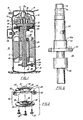
- Fig. 2 is an exploded perspective view of a two-part lower bearing for the scroll compressor of Fig.1.
- Figs. 3 and 4 are sectional elevations of rotor assembly and of partly constructed housing with stator, crankshaft, and bearings, respectively, for the scroll compressor of Fig. 1.
- Fig. 5 shows an alignment arbor which can be employed in assembly of the scroll compressor of the preferred embodiments of this invention.
- Fig. 1 shows a scroll compressor 10 which has a vertically oriented tubular cylindrical shell 11.
- a base 12 in the form of a bottom cap closes off a lower end of the shell 11, and a top 13 in the form of an upper cap closes off a top end of the shell 11.
- a high pressure dome 14 is formed in the upper cap 13, and has a high pressure outlet 15 through which compressed gas is conducted from a center outlet of a compressor scroll assembly 16.
- the scroll assembly 16 includes a fixed scroll 17 that has a spiral involute wrap 18, and a facing orbiting scroll 19 that has an involute wrap 20 that is interleaved with the fixed scroll wrap 18.
- a male stub 21 extends downward from the axis of the orbiting scroll 19, and constitutes the driven member which revolves in orbiting fashion around the axis of the fixed scroll 17.
- low pressure gas enters the interleaved scroll wrap 18 and 20 at the periphery thereof, and then is carried and compresses and discharged from the center of the interleaved scrolls.
- An upper bearing 23 is fixedly supported within the shell 11 just below the scroll compressor assembly 16.
- the bearing 23 is rotationally supported in a generally cylindrical upper journal 24, i.e., a crankcase, coaxial with the center of the fixed scroll.
- a stator 25 which constitutes the motor armature for the scroll compressor 10 is also fixedly mounted within the tubular shell 11.
- An electrical connector 26 which is mounted on the side of the shell 11 provides electric current to the windings on the stator 25.
- the stator 25 has a central axial passage 27, which is cylindrical and has a predetermined, uniform radius.
- a lower bearing assembly 28, shown in more detail in Fig. 2, consists of two major parts.
- An outer ring portion 29, in the form of a spider, has a ring 30 with an opening 31 that has a radius as great as or greater than the radius of the stator passage 27.
- a number of legs 32 radiate from the ring 30, and provide surfaces which can be welded to the inside surface of the tubular shell 11.
- a number of bores 33 extend axially through the ring 30 outside the opening 31.
- An inner bearing plate 34 has a central journal 35 and a number of axial bores 36 that are in registry with the bores 33 of the outer ring portion 29.
- the inner bearing plate 34 can be accurately positioned on the outer ring portion 29, and attached thereto with bolts 37 that pass through aligned ones of the bores 33 and 36.
- a rotor assembly 38 also shown with reference to Fig. 3, has a generally cylindrical rotor 39 that has a radius that is slightly less than the radius of the stator cylindrical passage 27.
- the rotor 39 is positioned within the passage 27, with a small annular gap between the rotor and the stator.
- a crankshaft 40 for the rotor assembly extends axially through the rotor 39 and has a generally cylindrical crank or journal 41 situated at its upper end.
- the journal 41 has an off-axis receptacle to receive the male stub 21 of the driven orbiting scroll 19.
- the cylindrical journal 41 is received in the bearing 23 of the housing 24.
- an eccentric counter weight 43 that is integrally formed as part of the crankshaft 40 and is situated diametrically opposite the offset of the orbiting scroll.
- the counterweight 43 is in the form of a portion of a cylinder that has a radius smaller than the predetermined radius of the stator passage 27. That is, the radial extent of the counterweight 43 is small enough to pass through the passage 27 when the stator assembly 38 is installed from below.
- a lower end 44 of the shaft 40 protrudes from a lower end of rotor 39 and is journaled in the central journal 35 of the inner bearing plate 34.
- An alignment arbor 50 as shown in Fig. 4, is employed to construct the scroll compressor 10.
- the arbor 50 is an alignment tool generally in the shape of a spindle.
- the first step is to fixedly secure the stator 25 within the tubular shell 11 by a shrinking or press fit. This may be suitably done by heating the shell 11 and the placing stator in the heated shell and permitting the shell to cool.
- the arbor 50 has three selectively pressurizeable zones 51, 52, 53 and associated therewith are shoulders 51a, 52a and a flange 54, respectively, for axially locating the parts.
- the lower bearing ring 29 is placed on the arbor 50 such that the ring 29 rests on the flange 54.
- Arbor 50 together with the bearing ring 29 is inserted into the shell 11 such that the shoulder 52a engages the stator 25.
- the crankcase 24 which carries the bearing 23 is placed into the shell 11 and on the arbor 50 such that the bearing 23 engages the shoulder 51a.
- the zone 52 With the arbor 50 properly axially located by the engagement of the shoulder 52a with the stator 25, the zone 52 is pressurized. This properly locates the arbor 52 radially and fixedly locates the arbor 50 with respect to the stator 25.
- the zone 51 is then pressurized which properly radially locates the bearing 23 and the crankcase 24 such that the crankcase 24 can be welded to the shell 11 and the zone 51 can be depressurized.
- the zone 53 is then pressurized which properly radially locates lower bearing ring 29 which may then be welded to shell 11.
- the zones 52 and 53 are then depressurized which permits the arbor 50 to be withdrawn for the stator 25 and the shell 11.
- the zone 52 must be kept pressurized during the foregoing procedure because assembly is keyed off the stator 25 rather than the shell 11.
- the three zones 51, 52, and 53 have individual radially expandable portions allowing the alignment arbor 50 to be expanded radially to lock the upper bearing, and the lower bearing outer ring portion in predetermined, precisely aligned positions relative to the stator 25.
- a radial flange 54 ensures the lower bearing outer ring portion 29 is perpendicular to the bearing axis.
- a mount 55 on the alignment arbor positions the arbor on an assembly station, workbench, or the like.
- the housing 24 and outer ring portion 29 With the housing 24 and lower bearing outer ring portion 29 positioned and held in place by the alignment arbor 50, the housing 24 and outer ring portion 29 can be welded or otherwise affixed in place onto the shell 11. Then, the alignment arbor can be withdrawn. At this stage, the rotor assembly can be installed through the opening 31 in the lower bearing outer ring portion 29, so that the journal 41 at the upper end of the shaft 40 is accurately positioned in the bearing 23, and the rotor 39 is accurately positioned within the cylindrical passage 27 in the stator 25. The inner bearing plate 34 is then installed onto the lower bearing outer ring portion 29 so that the journal 35 carries the lower end 44 of the shaft in precise alignment with respect to the housing 24 and stator 25. At that time, the remaining elements such as the scroll compressor assembly 16 can be installed, and the housing closed off with the upper and lower end caps 12 and 13.
Landscapes
- Engineering & Computer Science (AREA)
- Mechanical Engineering (AREA)
- General Engineering & Computer Science (AREA)
- Rotary Pumps (AREA)
- Applications Or Details Of Rotary Compressors (AREA)
- Compressor (AREA)
Applications Claiming Priority (2)
| Application Number | Priority Date | Filing Date | Title |
|---|---|---|---|
| US445780 | 1989-12-04 | ||
| US07/445,780 US5042150A (en) | 1989-12-04 | 1989-12-04 | Method of assembling a scroll compressor |
Publications (2)
| Publication Number | Publication Date |
|---|---|
| EP0432083A1 true EP0432083A1 (de) | 1991-06-12 |
| EP0432083B1 EP0432083B1 (de) | 1993-08-04 |
Family
ID=23770163
Family Applications (1)
| Application Number | Title | Priority Date | Filing Date |
|---|---|---|---|
| EP90630194A Expired - Lifetime EP0432083B1 (de) | 1989-12-04 | 1990-11-15 | Spiralverdichter und Montageverfahren dafür |
Country Status (11)
| Country | Link |
|---|---|
| US (1) | US5042150A (de) |
| EP (1) | EP0432083B1 (de) |
| JP (1) | JP2886679B2 (de) |
| KR (1) | KR0143405B1 (de) |
| AR (1) | AR245981A1 (de) |
| BR (1) | BR9006093A (de) |
| DE (1) | DE69002595T2 (de) |
| DK (1) | DK0432083T3 (de) |
| ES (1) | ES2043338T3 (de) |
| MX (1) | MX171384B (de) |
| MY (1) | MY104552A (de) |
Cited By (2)
| Publication number | Priority date | Publication date | Assignee | Title |
|---|---|---|---|---|
| WO2000063560A1 (en) * | 1999-04-20 | 2000-10-26 | Danfoss Maneurop S.A. | Alignment of the bearings of the crankshaft of a scroll compressor |
| WO2009091880A1 (en) * | 2008-01-17 | 2009-07-23 | Bitzer Scroll Inc. | Scroll compressor build assembly |
Families Citing this family (21)
| Publication number | Priority date | Publication date | Assignee | Title |
|---|---|---|---|---|
| JP2712777B2 (ja) * | 1990-07-13 | 1998-02-16 | 三菱電機株式会社 | スクロール圧縮機 |
| KR950004541B1 (ko) * | 1990-10-04 | 1995-05-02 | 미쓰비시덴키 가부시키가이샤 | 스크롤압축기 및 그 제조방법 |
| US5142762A (en) * | 1990-10-22 | 1992-09-01 | United Technologies Corporation | Air cycle machine alignment |
| JP3078369B2 (ja) * | 1991-10-24 | 2000-08-21 | サンデン株式会社 | 圧縮機 |
| US5379516A (en) * | 1993-04-06 | 1995-01-10 | Carrier Corporation | Scroll compressor pump cartridge assembly |
| US5832604A (en) * | 1995-09-08 | 1998-11-10 | Hydro-Drill, Inc. | Method of manufacturing segmented stators for helical gear pumps and motors |
| US6158989A (en) * | 1997-12-15 | 2000-12-12 | Scroll Technologies | Scroll compressor with integral outer housing and fixed scroll member |
| US6247909B1 (en) * | 1999-08-18 | 2001-06-19 | Scroll Technologies | Bearing assembly for sealed compressor |
| US6280155B1 (en) | 2000-03-21 | 2001-08-28 | Tecumseh Products Company | Discharge manifold and mounting system for, and method of assembling, a hermetic compressor |
| US6499977B2 (en) | 2000-04-24 | 2002-12-31 | Scroll Technologies | Scroll compressor with integral outer housing and a fixed scroll member |
| JP4371189B2 (ja) * | 2000-08-25 | 2009-11-25 | 株式会社富士通ゼネラル | スクロール圧縮機の調芯装置およびその調芯方法 |
| JP4371231B2 (ja) * | 2005-01-17 | 2009-11-25 | 株式会社富士通ゼネラル | スクロール圧縮機の調芯装置およびその調芯方法 |
| US20060159579A1 (en) * | 2005-01-20 | 2006-07-20 | Skinner Robin G | Motor-compressor unit mounting arrangement for compressors |
| US8147229B2 (en) | 2005-01-20 | 2012-04-03 | Tecumseh Products Company | Motor-compressor unit mounting arrangement for compressors |
| JP4837331B2 (ja) * | 2005-08-11 | 2011-12-14 | 三菱電機株式会社 | スクロール流体機械の位置決め方法およびその装置、並びにスクロール流体機械の組み立て方法およびその装置 |
| US7550881B1 (en) * | 2006-01-17 | 2009-06-23 | Honeywell International Inc. | Vibration damper for generator or motor stator |
| US8342795B2 (en) * | 2008-04-24 | 2013-01-01 | Emerson Climate Technologies, Inc. | Support member for optimizing dynamic load distribution and attenuating vibration |
| US20130189133A1 (en) * | 2012-01-19 | 2013-07-25 | Danfoss (Tianjin) Ltd. | Compressor and method of assembling compressor |
| US9458850B2 (en) | 2012-03-23 | 2016-10-04 | Bitzer Kuehlmaschinenbau Gmbh | Press-fit bearing housing with non-cylindrical diameter |
| CN105649979B (zh) * | 2016-03-29 | 2024-06-11 | 丁波 | 空压机动盘与静盘平面间隙精准的装配方法以及改良结构 |
| CN119070567B (zh) * | 2024-08-08 | 2025-08-19 | 无锡金汇精工机械制造有限公司 | 一种电机转子铁芯的叠压工装 |
Family Cites Families (6)
| Publication number | Priority date | Publication date | Assignee | Title |
|---|---|---|---|---|
| JPS5915691A (ja) * | 1982-07-15 | 1984-01-26 | Sanden Corp | スクロ−ル型流体装置 |
| JPS59224493A (ja) * | 1983-06-03 | 1984-12-17 | Mitsubishi Electric Corp | スクロ−ル圧縮機 |
| JPS60243301A (ja) * | 1984-05-18 | 1985-12-03 | Mitsubishi Electric Corp | スクロール流体機械及びその流体機械の組立て方法 |
| US4655696A (en) * | 1985-11-14 | 1987-04-07 | American Standard Inc. | Anti-rotation coupling for a scroll machine |
| JPS62186084A (ja) * | 1986-02-12 | 1987-08-14 | Mitsubishi Electric Corp | スクロ−ル圧縮機 |
| US4811471A (en) * | 1987-11-27 | 1989-03-14 | Carrier Corporation | Method of assembling scroll compressors |
-
1989
- 1989-12-04 US US07/445,780 patent/US5042150A/en not_active Expired - Lifetime
-
1990
- 1990-11-15 DE DE90630194T patent/DE69002595T2/de not_active Expired - Fee Related
- 1990-11-15 ES ES90630194T patent/ES2043338T3/es not_active Expired - Lifetime
- 1990-11-15 DK DK90630194.0T patent/DK0432083T3/da active
- 1990-11-15 EP EP90630194A patent/EP0432083B1/de not_active Expired - Lifetime
- 1990-11-29 MX MX023529A patent/MX171384B/es unknown
- 1990-11-30 JP JP2341228A patent/JP2886679B2/ja not_active Expired - Fee Related
- 1990-11-30 MY MYPI90002112A patent/MY104552A/en unknown
- 1990-11-30 AR AR90318515A patent/AR245981A1/es active
- 1990-11-30 BR BR909006093A patent/BR9006093A/pt not_active IP Right Cessation
- 1990-12-03 KR KR1019900019781A patent/KR0143405B1/ko not_active Expired - Fee Related
Non-Patent Citations (6)
| Title |
|---|
| PATENT ABSTRACTS OF JAPAN, vol. 10, no. 153 (M-484)[2209], 3rd June 1986; & JP-A-61 8487 (TOSHIBA K.K.) 16-01-1986 * |
| PATENT ABSTRACTS OF JAPAN, vol. 10, no. 196 (M-497)[2252], 10th July 1986; & JP-A-61 40 472 (TOSHIBA CORP.) 26-02-1986 * |
| PATENT ABSTRACTS OF JAPAN, vol. 11, no. 380 (M-650)[2827], 11th December 1987; & JP-A-62 150 001 (DAIKIN IND. LTD) 04-07-1987 * |
| PATENT ABSTRACTS OF JAPAN, vol. 13, no. 148 (M-812)[3496], 11th April 1989; & JP-A-63 309 794 (SANYO ELECTRIC CO., LTD) 16-12-1988 * |
| PATENT ABSTRACTS OF JAPAN, vol. 13, no. 446 (M-877)[3794], 6th October 1989; & JP-A-1 170 779 (MATSUSHITA ELECTRIC IND. CO., LTD) 05-07-1989 * |
| PATENT ABSTRACTS OF JAPAN, vol. 14, no. 357 (M-1005)[4300], 2nd August 1990; & JP-A³2 125 986 (DAIKIN IND. LTD) 14-05-1990 * |
Cited By (5)
| Publication number | Priority date | Publication date | Assignee | Title |
|---|---|---|---|---|
| WO2000063560A1 (en) * | 1999-04-20 | 2000-10-26 | Danfoss Maneurop S.A. | Alignment of the bearings of the crankshaft of a scroll compressor |
| FR2792718A1 (fr) * | 1999-04-20 | 2000-10-27 | Danfoss Maneurop S A | Procede de montage et d'alignement des paliers du vilebrequin d'un compresseur scroll, et dispositif pour la mise en oeuvre de ce procede |
| US6616429B1 (en) | 1999-04-20 | 2003-09-09 | Danfoss Maneurop S.A. | Apparatus and method for alignment of the bearing of the crankshaft of a scroll compressor and a scroll compressor and device for carrying out this method |
| WO2009091880A1 (en) * | 2008-01-17 | 2009-07-23 | Bitzer Scroll Inc. | Scroll compressor build assembly |
| US8152500B2 (en) | 2008-01-17 | 2012-04-10 | Bitzer Scroll Inc. | Scroll compressor build assembly |
Also Published As
| Publication number | Publication date |
|---|---|
| JPH03182691A (ja) | 1991-08-08 |
| BR9006093A (pt) | 1991-09-24 |
| MY104552A (en) | 1994-04-30 |
| MX171384B (es) | 1993-10-21 |
| JP2886679B2 (ja) | 1999-04-26 |
| ES2043338T3 (es) | 1993-12-16 |
| KR0143405B1 (ko) | 1998-08-01 |
| DE69002595D1 (de) | 1993-09-09 |
| DE69002595T2 (de) | 1994-01-05 |
| DK0432083T3 (da) | 1993-12-13 |
| AR245981A1 (es) | 1994-03-30 |
| EP0432083B1 (de) | 1993-08-04 |
| US5042150A (en) | 1991-08-27 |
| KR910012540A (ko) | 1991-08-08 |
Similar Documents
| Publication | Publication Date | Title |
|---|---|---|
| EP0432083B1 (de) | Spiralverdichter und Montageverfahren dafür | |
| US6488489B2 (en) | Method of aligning scroll compressor components | |
| EP0479412B1 (de) | Oldham's Kupplung für Spiralverdichter | |
| EP1188928B1 (de) | Spiralverdichter | |
| EP0430854B1 (de) | Mehrteilige Exzenterwelle | |
| US5873710A (en) | Motor spacer for hermetic motor-compressor | |
| JP3567237B2 (ja) | かしめられた外殻を備えた圧縮機組立体 | |
| US6682327B2 (en) | Method of aligning scroll compressor components | |
| US8936449B2 (en) | Hermetic compressor and manufacturing method thereof | |
| JPS61118588A (ja) | 回転圧縮機およびの主軸受 | |
| EP0432084B1 (de) | Spiralverdichterkurbelwelle mit Lager und Gegengewicht | |
| EP0478795B1 (de) | Spiralverdichter | |
| CN116097001A (zh) | 压缩机、压缩机的制造方法 | |
| EP0283045B1 (de) | Spiralkompresseur | |
| US11713756B2 (en) | Scroll compressor | |
| CN107850070A (zh) | 涡旋压缩机、涡旋压缩机的制造方法 | |
| GB2344380A (en) | Force-fit scroll compressor | |
| JPH1189138A (ja) | 磁石モータ | |
| JP2609839B2 (ja) | スクロール型圧縮装置 | |
| KR101708307B1 (ko) | 밀폐형 압축기 및 그의 제조방법 | |
| JP2010265845A (ja) | 圧縮機の製造方法および圧縮機 | |
| JP3895956B2 (ja) | スクロール圧縮機の製造方法 | |
| JP2604325B2 (ja) | スクロール圧縮機 | |
| JP2901681B2 (ja) | 密閉形スクロール圧縮機 | |
| JP2010163882A (ja) | スクロール型流体機械 |
Legal Events
| Date | Code | Title | Description |
|---|---|---|---|
| PUAI | Public reference made under article 153(3) epc to a published international application that has entered the european phase |
Free format text: ORIGINAL CODE: 0009012 |
|
| AK | Designated contracting states |
Kind code of ref document: A1 Designated state(s): BE DE DK ES FR IT |
|
| 17P | Request for examination filed |
Effective date: 19910731 |
|
| 17Q | First examination report despatched |
Effective date: 19910920 |
|
| GRAA | (expected) grant |
Free format text: ORIGINAL CODE: 0009210 |
|
| AK | Designated contracting states |
Kind code of ref document: B1 Designated state(s): BE DE DK ES FR IT |
|
| PG25 | Lapsed in a contracting state [announced via postgrant information from national office to epo] |
Ref country code: IT Free format text: LAPSE BECAUSE OF FAILURE TO SUBMIT A TRANSLATION OF THE DESCRIPTION OR TO PAY THE FEE WITHIN THE PRE;WARNING: LAPSES OF ITALIAN PATENTS WITH EFFECTIVE DATE BEFORE 2007 MAY HAVE OCCURRED AT ANY TIME BEFORE 2007. THE CORRECT EFFECTIVE DATE MAY BE DIFFERENT FROM THE ONE RECORDED.SCRIBED TIME-LIMIT Effective date: 19930804 |
|
| ET | Fr: translation filed | ||
| REF | Corresponds to: |
Ref document number: 69002595 Country of ref document: DE Date of ref document: 19930909 |
|
| REG | Reference to a national code |
Ref country code: DK Ref legal event code: T3 |
|
| REG | Reference to a national code |
Ref country code: ES Ref legal event code: FG2A Ref document number: 2043338 Country of ref document: ES Kind code of ref document: T3 |
|
| PLBE | No opposition filed within time limit |
Free format text: ORIGINAL CODE: 0009261 |
|
| STAA | Information on the status of an ep patent application or granted ep patent |
Free format text: STATUS: NO OPPOSITION FILED WITHIN TIME LIMIT |
|
| 26N | No opposition filed | ||
| PGFP | Annual fee paid to national office [announced via postgrant information from national office to epo] |
Ref country code: DK Payment date: 19951016 Year of fee payment: 6 |
|
| PGFP | Annual fee paid to national office [announced via postgrant information from national office to epo] |
Ref country code: ES Payment date: 19951108 Year of fee payment: 6 |
|
| PG25 | Lapsed in a contracting state [announced via postgrant information from national office to epo] |
Ref country code: DK Effective date: 19961115 |
|
| REG | Reference to a national code |
Ref country code: DK Ref legal event code: EBP |
|
| PG25 | Lapsed in a contracting state [announced via postgrant information from national office to epo] |
Ref country code: ES Free format text: LAPSE BECAUSE OF NON-PAYMENT OF DUE FEES Effective date: 19961116 |
|
| PGFP | Annual fee paid to national office [announced via postgrant information from national office to epo] |
Ref country code: DE Payment date: 19981120 Year of fee payment: 9 |
|
| PGFP | Annual fee paid to national office [announced via postgrant information from national office to epo] |
Ref country code: FR Payment date: 19981125 Year of fee payment: 9 |
|
| PGFP | Annual fee paid to national office [announced via postgrant information from national office to epo] |
Ref country code: BE Payment date: 19990119 Year of fee payment: 9 |
|
| PG25 | Lapsed in a contracting state [announced via postgrant information from national office to epo] |
Ref country code: BE Free format text: LAPSE BECAUSE OF NON-PAYMENT OF DUE FEES Effective date: 19991130 |
|
| BERE | Be: lapsed |
Owner name: CARRIER CORP. Effective date: 19991130 |
|
| PG25 | Lapsed in a contracting state [announced via postgrant information from national office to epo] |
Ref country code: FR Free format text: LAPSE BECAUSE OF NON-PAYMENT OF DUE FEES Effective date: 20000731 |
|
| PG25 | Lapsed in a contracting state [announced via postgrant information from national office to epo] |
Ref country code: DE Free format text: LAPSE BECAUSE OF NON-PAYMENT OF DUE FEES Effective date: 20000901 |
|
| REG | Reference to a national code |
Ref country code: FR Ref legal event code: ST |
|
| REG | Reference to a national code |
Ref country code: ES Ref legal event code: FD2A Effective date: 20010503 |