EP0432265B1 - Versorgungsleitungsanordnung und -vorrichtung für ultrareines wasser - Google Patents
Versorgungsleitungsanordnung und -vorrichtung für ultrareines wasser Download PDFInfo
- Publication number
- EP0432265B1 EP0432265B1 EP89907833A EP89907833A EP0432265B1 EP 0432265 B1 EP0432265 B1 EP 0432265B1 EP 89907833 A EP89907833 A EP 89907833A EP 89907833 A EP89907833 A EP 89907833A EP 0432265 B1 EP0432265 B1 EP 0432265B1
- Authority
- EP
- European Patent Office
- Prior art keywords
- pipe
- pure water
- ultra
- connection
- branching
- Prior art date
- Legal status (The legal status is an assumption and is not a legal conclusion. Google has not performed a legal analysis and makes no representation as to the accuracy of the status listed.)
- Expired - Lifetime
Links
- 229910021642 ultra pure water Inorganic materials 0.000 title claims abstract description 103
- 239000012498 ultrapure water Substances 0.000 title claims abstract description 103
- XLYOFNOQVPJJNP-UHFFFAOYSA-N water Substances O XLYOFNOQVPJJNP-UHFFFAOYSA-N 0.000 claims abstract description 78
- 238000011144 upstream manufacturing Methods 0.000 claims description 36
- 229920005989 resin Polymers 0.000 claims description 9
- 239000011347 resin Substances 0.000 claims description 9
- QDOXWKRWXJOMAK-UHFFFAOYSA-N dichromium trioxide Chemical compound O=[Cr]O[Cr]=O QDOXWKRWXJOMAK-UHFFFAOYSA-N 0.000 claims description 8
- BQCIDUSAKPWEOX-UHFFFAOYSA-N 1,1-Difluoroethene Chemical compound FC(F)=C BQCIDUSAKPWEOX-UHFFFAOYSA-N 0.000 claims description 5
- 239000004696 Poly ether ether ketone Substances 0.000 claims description 5
- BZHJMEDXRYGGRV-UHFFFAOYSA-N Vinyl chloride Chemical compound ClC=C BZHJMEDXRYGGRV-UHFFFAOYSA-N 0.000 claims description 5
- 229920002530 polyetherether ketone Polymers 0.000 claims description 5
- 229910001220 stainless steel Inorganic materials 0.000 claims description 5
- 239000010935 stainless steel Substances 0.000 claims description 5
- 238000004519 manufacturing process Methods 0.000 abstract description 3
- 238000000034 method Methods 0.000 description 9
- 239000000463 material Substances 0.000 description 6
- 239000004065 semiconductor Substances 0.000 description 5
- VYPSYNLAJGMNEJ-UHFFFAOYSA-N Silicium dioxide Chemical compound O=[Si]=O VYPSYNLAJGMNEJ-UHFFFAOYSA-N 0.000 description 4
- 230000007423 decrease Effects 0.000 description 3
- 230000000694 effects Effects 0.000 description 3
- 239000012535 impurity Substances 0.000 description 3
- 230000001954 sterilising effect Effects 0.000 description 3
- 241000894006 Bacteria Species 0.000 description 2
- 239000002033 PVDF binder Substances 0.000 description 2
- 239000000356 contaminant Substances 0.000 description 2
- 230000001276 controlling effect Effects 0.000 description 2
- 238000010828 elution Methods 0.000 description 2
- 238000009434 installation Methods 0.000 description 2
- 244000005700 microbiome Species 0.000 description 2
- 230000004048 modification Effects 0.000 description 2
- 238000012986 modification Methods 0.000 description 2
- 230000003647 oxidation Effects 0.000 description 2
- 238000007254 oxidation reaction Methods 0.000 description 2
- 230000000704 physical effect Effects 0.000 description 2
- 229920002981 polyvinylidene fluoride Polymers 0.000 description 2
- 230000035755 proliferation Effects 0.000 description 2
- 239000000377 silicon dioxide Substances 0.000 description 2
- OKTJSMMVPCPJKN-UHFFFAOYSA-N Carbon Chemical compound [C] OKTJSMMVPCPJKN-UHFFFAOYSA-N 0.000 description 1
- QVGXLLKOCUKJST-UHFFFAOYSA-N atomic oxygen Chemical compound [O] QVGXLLKOCUKJST-UHFFFAOYSA-N 0.000 description 1
- 229910052799 carbon Inorganic materials 0.000 description 1
- 230000010485 coping Effects 0.000 description 1
- 230000003247 decreasing effect Effects 0.000 description 1
- 238000000151 deposition Methods 0.000 description 1
- 238000010586 diagram Methods 0.000 description 1
- 239000000428 dust Substances 0.000 description 1
- RTZKZFJDLAIYFH-UHFFFAOYSA-N ether Substances CCOCC RTZKZFJDLAIYFH-UHFFFAOYSA-N 0.000 description 1
- 238000001704 evaporation Methods 0.000 description 1
- 230000008020 evaporation Effects 0.000 description 1
- 239000012530 fluid Substances 0.000 description 1
- 230000001939 inductive effect Effects 0.000 description 1
- 150000002500 ions Chemical class 0.000 description 1
- 238000005304 joining Methods 0.000 description 1
- 229910052760 oxygen Inorganic materials 0.000 description 1
- 239000001301 oxygen Substances 0.000 description 1
- 239000002245 particle Substances 0.000 description 1
- 238000000746 purification Methods 0.000 description 1
- 230000001105 regulatory effect Effects 0.000 description 1
- 239000007787 solid Substances 0.000 description 1
- 239000000126 substance Substances 0.000 description 1
Images


Classifications
-
- B—PERFORMING OPERATIONS; TRANSPORTING
- B01—PHYSICAL OR CHEMICAL PROCESSES OR APPARATUS IN GENERAL
- B01D—SEPARATION
- B01D61/00—Processes of separation using semi-permeable membranes, e.g. dialysis, osmosis or ultrafiltration; Apparatus, accessories or auxiliary operations specially adapted therefor
- B01D61/14—Ultrafiltration; Microfiltration
- B01D61/22—Controlling or regulating
-
- C—CHEMISTRY; METALLURGY
- C02—TREATMENT OF WATER, WASTE WATER, SEWAGE, OR SLUDGE
- C02F—TREATMENT OF WATER, WASTE WATER, SEWAGE, OR SLUDGE
- C02F1/00—Treatment of water, waste water, or sewage
- C02F1/006—Water distributors either inside a treatment tank or directing the water to several treatment tanks; Water treatment plants incorporating these distributors, with or without chemical or biological tanks
-
- C—CHEMISTRY; METALLURGY
- C02—TREATMENT OF WATER, WASTE WATER, SEWAGE, OR SLUDGE
- C02F—TREATMENT OF WATER, WASTE WATER, SEWAGE, OR SLUDGE
- C02F1/00—Treatment of water, waste water, or sewage
- C02F1/30—Treatment of water, waste water, or sewage by irradiation
- C02F1/32—Treatment of water, waste water, or sewage by irradiation with ultraviolet light
-
- C—CHEMISTRY; METALLURGY
- C02—TREATMENT OF WATER, WASTE WATER, SEWAGE, OR SLUDGE
- C02F—TREATMENT OF WATER, WASTE WATER, SEWAGE, OR SLUDGE
- C02F1/00—Treatment of water, waste water, or sewage
- C02F1/44—Treatment of water, waste water, or sewage by dialysis, osmosis or reverse osmosis
- C02F1/444—Treatment of water, waste water, or sewage by dialysis, osmosis or reverse osmosis by ultrafiltration or microfiltration
-
- Y—GENERAL TAGGING OF NEW TECHNOLOGICAL DEVELOPMENTS; GENERAL TAGGING OF CROSS-SECTIONAL TECHNOLOGIES SPANNING OVER SEVERAL SECTIONS OF THE IPC; TECHNICAL SUBJECTS COVERED BY FORMER USPC CROSS-REFERENCE ART COLLECTIONS [XRACs] AND DIGESTS
- Y10—TECHNICAL SUBJECTS COVERED BY FORMER USPC
- Y10S—TECHNICAL SUBJECTS COVERED BY FORMER USPC CROSS-REFERENCE ART COLLECTIONS [XRACs] AND DIGESTS
- Y10S210/00—Liquid purification or separation
- Y10S210/90—Ultra pure water, e.g. conductivity water
Definitions
- the present invention relates to a piping system for supplying ultra-pure water to be used in large quantity in electronic industry such as semiconductor industry, or in biochemical and pharmaceutical industry.
- JP,Y2,62-34061 discloses a piping system as per the preamble of claim 1. Thereby, the water pressure is detected on the connection pipe by means of equipment PIC.
- This pressure control instrument acts on an automatic valve, so that the output of a pump is controlled.
- This system uses the problem of keeping a constant flow at the points of use. However, the said system has the drawback that counter flow occurs and pollutes the water.
- a system as shown in Fig. 3 has been known as a piping system for supplying ultra-pure water for electronics industry, especially in the application for the manufacture of semiconductor integrated circuits.
- the primary pure water produced by a primary ultra-pure water producing system (not shown) is supplied to a circulation tank 102 through a primary pure water supply pipe 101.
- the primary pure water stored in the circulation tank 102 is pressurized by a pressure pump 103 and is purified through ultraviolet sterilizing unit (hereinafter referred as "UV sterilizing unit") 104, cartridge polishers 105, 106 and 107 and ultrafilter units 108 and 109.
- UV sterilizing unit hereinafter referred as "UV sterilizing unit”
- 122 represents a drain pipe for ultrafilter unit.
- the ultra-pure water thus purified is supplied to each of the user points 119, 120 and 121 through an outward pipe, connection pipes 113, 114 and 115 and branching valves 116, 117 and 118.
- connection pipes 113, 114 and 115 After passing through connection pipes 113, 114 and 115, the ultra-pure water flows through a circulation route to return to the circulation tank 102 through a return pipe 112.
- the connection pipes 113, 114 and 115 are composed of upstream pipe sections 113-1, 114-1 and 115-1 and downstream pipe sections 113-2, 114-2 and 115-2.
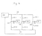
- Fig. 4 shows a piping system for supplying ultra-pure water of Fig. 3.
- 201 represents the entire ultra-pure water producing system.
- 131, 132 and 133 show the branching points of the connection pipes 113, 114 and 115 to the user points.
- the branching valves 116, 117 and 118 are integrally composed of the branching points 131, 132 and 133 respectively.
- the ultra-pure water produced by such ultra-water producing unit is often supplied to the ultra-pure water using unit (hereinafter called as "user point", meaning the place where ultra-pure water is used).
- user point meaning the place where ultra-pure water is used.
- the number of the user points is extremely many, while Fig. 3 shows an example where 3 user points are provided.
- the quantity of ultra-pure water flowing in the outward pipe 110 is decreased when the number of the user points is increased, i.e. when the number of branching points is increased.
- the quantity of water in the return pipe 112 is increased when the number of the branching points is increased. Because the condition to use ultra-pure water at each user point is not constant, it has been difficult in the past to maintain the pressure between the outward pipe 110 and return pipe 112 of each of the connection pipes 113, 114 and 115 at constant level, and it has been impossible to supply a constant quantity of ultra-pure water to each of the user points at all times.
- connection pipes 113, 114 and 115 have the same inner diameter upstream and downstream of the branching points.
- the branching valves 116, 117 and 118 are designed in such manner that, when they are opened, the pressure at the branching points 131, 132 and 133 is approximately equal to the atmospheric pressure.
- the branching valve 117 is opened when ultra-pure water is used in the ultra-pure water using unit 120, the pressure at the branching point 132 is approximately equal to the atmospheric pressure.
- the pressure of ultra-pure water flowing in the outward pipe 110 and the return pipe 112 is adjusted to the valve higher by 1 - 2 kg/cm2 than the atmospheric pressure in normal case.
- the ultra-pure water flowing from the return pipe 112 to the branching pipe 132 is the ultra-pure water, which has passed through the other connection pipes 113 and 115 and the return pipe 112.
- it contains more impurities than the ultra-pure water, which has flown through only the upstream pipe section 114-1 of the connection pipe from the outward pipe 110 because of the elution of impurities from piping materials.
- the resistivity of ultra-pure water supplied to the ultra-pure using unit 120 through only the upstream pipe section 114-1 of the connection pipe from the outward pipe 110 is 18.2 M ⁇ cm.
- the resistivity of the water to be supplied to the ultra-pure water using unit 120 through the downstream pipe section 114-2 of connection pipe from the return pipe 112 is 18.0 M ⁇ cm.
- This difference in resistivity 0.2 M ⁇ cm corresponds to the difference of concentration of about 0.2 ppb.
- the object of the present invention is to offer a piping system, which can supply a constant quantity of ultra-pure water to each of the user points at all times and can provide stable supply of ultra-pure water with ultra-high putity by preventing the counterflow from the return pipe to the ultra-pure water using unit.
- the invention according to claim 1 relates to a piping system comprising the features of the preamble of claim 1.
- the said piping system is characterized in that means for controlling the output of said pump are provided to keep the water pressure at a constant level by detecting the water pressure in said output pipe, and in that the connection pipes are so designed that the energy loss - when water is passed upstream of the branching pipe of that connection pipe - is equal to the energy loss when water is passed downstream of said branching pipe.
- connection pipe has larger pipe diameter in upstream than in downstream.
- the invention of claim 3 describes a piping system according to claim 1, wherein said branching valve is such a valve which can limit the flow rate so that the pressure upstream is higher than the pressure downstream.
- the invention of claim 4 describes a piping system according to claim 1, wherein there are provided two or more combinations of said outward pipe and said return pipe between said final purifiying unit and the ultra-pure water using unit.
- connection pipe is contained partially or totally in said ultra-pure water using unit.
- the invention of claim 6 describes a piping system for supplying ultra-pure water according to one of the claims 1 to 5, wherein a plurality of said branching pipes are furnished on said connection pipe.
- the invention of claim 7 is a piping system according to claim 1, wherein the pipe diameter of said connection pipe is gradually reduced according to the arrangement order of said branching pipe arranged from said outward pipe to said return pipe.
- the invention of claim 8 offers a piping system according to claim 7, wherein said branching valve is furnished at the branching portion between said connection pipe and said outward pipe and at the connection between said connection pipe and said return pipe.
- the invention of claim 9 offers a piping system according to claim 1, wherein said outward pipe, said return pipe and said connection pipe are made of high purity vinyl chloride resin, vinylidene fluoride resin or poiyether-ether ketone.
- the invention of claim 10 offers a piping system for supplying ultra-pure water according to one of the claims 1 to 9, wherein said outward pipe, said return pipe and said connection pipe are made of stainless steel having inner surface, on which passive state film made primarily of Cr2O3 is formed.
- the pressure of water flow from pump is controlled by control means and the pressure in the outward pipe and the return pipe is maintained at constant level.
- Claim 9 offers a piping system according to Claim 1, wherein said branching valve is furnished at the branching portion between said connection pipe and said outward pipe and at the connection between said connection pipe and said return pipe.
- the invention of Claim 10 offers a piping system for supplying ultra-pure water according to one of the Claims 1 to 9, wherein said outward pipe, said return pipe and said connection pipe are made of high purity vinyl chloride resin, vinylidene fluoride resin or polyether-ether ketone.
- the invention of Claim 11 is a piping system according to Claim 1, wherein said outward pipe, said return pipe and said connection pipe are made of stainless steel having inner surface, on which passive state film made primarily of Cr2O3 is formed.
- the pressure of water flow from pump is controlled by control means, and the pressure in the outward pipe and the return pipe is maintained at constant level.
- the energy loss when water passes through each of the connection pipes is equal to each other, and a constant quantity of ultra-pure water can be supplied to each user point through connection pipes.
- the purity of ultra-pure water can be extensively improved when high purity vinyl chloride resin, vinylidene fluoride, vinylidene fluoride resin or polyether-ether ketone are selected as piping material and counterflow is prevented by setting the pipe diameter in upstream of the branching of connention pipe larger than that of upstream.
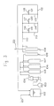
- FIG. 1 An embodiment of the present invention is given in Fig. 1.
- 501 represents a primary pure water supply pipe, and the primary pure water is supplied from a primary pure water producing unit (not shown) to a circulation tank 502 through a primary pure water supply pipe 501.
- the primary pure-water stored in the circulation tank 502 is pressurized by a pressure-feeding pump 503 and is purified as it passes through UV sterilizing unit 504, cartridge polishers 505, 506 and 507 as well as ultrafilter units 508 and 509.
- 522 is a drain pipe for ultrafilter unit.
- the ultra-pure water thus purified is supplied to the outward pipe 510 and is sent to the user points 519, 520 and 521 through connection pipes 513, 514 and 515 and the branching valves with controllable flow rate 516, 517 and 518.
- the present embodiment shows an example having 3 user points.
- connection pipes 513, 514 and 515 are control units for pump output, and the output of the pump 503 is controlled in such manner that the water pressure measured at the pressure sensor 551 is kept at contant level.
- the ultra-pure water passing through the connection pipes 513, 514 and 515 joins into the return pipe 512 and flows through the circulation route, returning to the circulation tank 502.
- connection pipes 513, 514 and 515 downstream of the branching valves 516, 517 and 518 is smaller than that of the pipes upstream.
- the output of the pressure pump 503 is controlled so that sufficient quantity of water is supplied to the outward pipe 510 when water flows in each of the connection pipes 513, 514 and 515 at flow rate of 0.5 m3/h, for example.
- ultra-pure water having ultra-high purity can be stably supplied to user points in the present embodiment.
- Fig. 2 shows a part of a piping system to explain the calculation example.
- 301 represents a pipe section upstream of connection pipe 514, and 302 a downstream pipe section of the connection pipe.
- 303 denotes a branching point of the outward pipe 510 and the connection pipe 514, 304 a confluence point of the connection pipe and the return pipe, 305 a branching point from the connection pipe 514 to the branching valve 517.
- connection pipe 514 is installed at horizontal position and it is straight.
- the length M1 of upstream pipe section 301 of the connection pipe 514 and that of the downstream pipe section 302 M2 are 2 m respectively and that inner diameter of upstream pipe section is 20 mm, and the flow rate and the pressure loss in the pipe are calculated when inner diameter of pipe of downstream pipe section 302 is changed.
- the pressure loss is considered only in the case where connection pipe 514 is installed at horizontal position and it is straight.
- the calculation procedure is as follows: When pipe diameter is given and branching valve 517 is closed, the water quantity flowing in the connection pipe 514 is estimated. This is supposed to be q1.
- the pressure loss between the branching point 303 and the confluence point 304 can be calculated by the equations (1) and (2). This value is supposed as ⁇ P1.
- the pressure loss generated in the upstream pipe section 301 becomes ultimately equal to ⁇ P1 when flow rate of branch flow increases, and pressure loss is no longer generated in the downstream pipe section 302.
- water does not flow in the downstream pipe section 302.
- Ultra-pure water flowing into the connection pipe 514 from the outward pipe 510 totally flows to user points, and ultra-pure water does not flow into the return pipe 512.
- the flow rate of branch flow to give such condition is regarded as maximum branch flow rate. Because the pressure loss at the upstream pipe section 301 is equal to ⁇ P1, the maximum branch flow rate can be calculated by the equations (4) and (5).
- the optimal branch flow rate, at which the flow velocity inside the downstream pipe section 302 is 0.3 m/s, can be obtained as follows:
- the pressure loss generated in the connection pipe 304 can be calculated from the flow velocity of 0.3 m/s. Because the difference ⁇ P1 is pressure loss generated at upstream pipe section 301, the flow rate flowing in the upstream pipe section 301 can be calculated.
- the difference between water quantity flowing in the upstream pipe section 301 and the water quantity flowing in the downstream pipe section 302 is the optimal branch flow rate.
- Table 1 summarizes the results of the calculation, by which maximum branch flow rate and optimal branch flow rate are obtained on various combinations of pipe diameters.
- the flow velocity at upstream and downstream of the branching point of connection pipe under various conditions are also shown in Table 1. From the calculation example of Table 1, it can be understood that optimal branch flow rate is not very high compared with water quantity flowing in connection pipe 514 when not branched off in case the pipe diameters upstream and downstream of the branching point 305 of connection pipe 514 are equal to each other, and that optimal branch flow rate may not be obtainable if the flow rate is low when not branched off.
- connection pipe 514 By sacrificing the uniformity of water quantity flowing in a plurality of connection pipes, the same effect as above can be obtained by providing a flow regulating valve near the confluence point with the return pipe 512 of the connection pipe 514. It cannot be guaranteed that minimum flow velocity is maintained at all portions, but the same effect can be obtained by furnishing a portion with smaller pipe diameter on a part of downstream pipe section of connection pipe.
- the flow rate to be branched off through branching valve is controlled.
- a valve of such type that the pressure at the branching point 305 becomes closer to the atmospheric pressure when branching valve 517 is opened in Fig. 2, excessive flow is branched off, and minimum flow velocity cannot be maintained in the downstream pipe section 302.
- a valve to control maximum flow rate is used as the branching valve 517.
- this value is high, it means that the change of water quantity flowing in the connection pipe 514 is high. If this change occurs suddenly, it leads to the so-called water hammer phenomenon.
- the pipe is vibrated and it may be damaged.
- the value of the equation (11) is 2 or less, or 3 or less at maximum.
- V' u1 /V u1 ⁇ P/(P-1) ⁇ .(0.3/V u2 ) ⁇ 3 (12)
- V u2 /0.3 ⁇ 3 (12) From the equation (13), V u2 ⁇ 0.9 [m/s] (14) If this is substituted in the above equation (12), P/(P-1) ⁇ 9 Therefore, P > 1.125.
- the piping system should be designed in such manner that the flow velocity in the connection pipe satisfies the relation of the equations (17) and (18).
- the values of d u1 , d u2 , V u1 and V' u1 are determined by the equations (15), (16) and (18) in relation to the using quantity q u .
- the length of the connection pipe 514 depends upon the position of the ultra-pure water using unit and is not constant, while it is possible to maintain the energy loss at constant level by furnishing pipe with different pipe diameter in the connection pipes.
- connection pipe there is one user point to be connected to one connection pipe, whereas there may be two or more user points.
- the pipe diameter of connection pipe may be gradually reduced according to the order of the branching points to be arranged from the outward pipe.
- T-type joint is furnished at the branching point of the outward pipe and the connection pipe and at the confluence point of the connection pipe and the return pipe, whereas it is also effective to provide branching valve without dead space.
- this branching valve is normally used in opened state.
- ultra-pure water is flowing in the outward pipe and the return pipe, without leaving any dead space.
- modification or repair is carried out with the branching valves in closed state on the connection pipe, the outward pipe and the return pipe only when user points are to be modified or repaired, the other user points are not affected.
- it is effective to provide branching valves in advance on the outward pipe and the return pipe at the position where the installation increase of ultra-pure water using unit is expected. In so doing, it is possible to connect new ultra-pure water using unit without affecting the other user points.
- modification, repair and installation increase are carried out, connection is made after inner surface of the pipe is completely cleaned up and dried.
- piping materials macromolecular materials such as vinyl chloride, PVDF (polyvinylidene fluoride resin), PEEK (polyether-ether ketone), etc. having smooth circular surface and containing fewer contaminants to be intermingled in ultra-pure water are used.
- piping material having lower elution of contaminants stainless steel may be used.
- Such stainless steel is produced by depositing passive state film (particularly, passive state film primarily composed of Cr2O3) by oxidation in ultra-high purity oxygen at 500 C - 600 C for 5 - 10 hours (particularly, oxidation at 550 C for 9 hours or more) after inner surface is electropolished and completely cleaned up and dried.
- the quality of ultra-pure water thus produced can be maintained by removing dust as solid matters or by removing bacteria or by removing ions, silica, organic substances, etc. dissolved in water.
- the system of the present embodiment to stably supply ultra-pure water of ultra-high purity to user points in a system having many user points.
- the same stable supply of ultra-pure water can be provided by controlling the output of pressure pump 503 to have the flow rate and the pressure as desired.
- the piping system for supplying ultra-pure water of this invention to supply ultra-pure water to a plurality of ultra-pure water in constant quantity by the control of pressure pump.
- the proliferation of microorganisms can be avoided by maintaining minimum flow velocity, and ultra-pure water can be stably supplied to the ultra-pure water using unit through strict selection of piping materials.
- the present invention it is possible to offer a piping system for supplying ultra-pure water, which can supply ultra-pure water to user points, thus coping with the requirements in an era of semiconductor integrated circuits having 64 MB memory.
Landscapes
- Water Supply & Treatment (AREA)
- Engineering & Computer Science (AREA)
- Chemical & Material Sciences (AREA)
- Organic Chemistry (AREA)
- Life Sciences & Earth Sciences (AREA)
- Hydrology & Water Resources (AREA)
- Environmental & Geological Engineering (AREA)
- Chemical Kinetics & Catalysis (AREA)
- Health & Medical Sciences (AREA)
- Toxicology (AREA)
- Pipeline Systems (AREA)
- Cleaning Or Drying Semiconductors (AREA)
- Treatment Of Water By Ion Exchange (AREA)
Claims (10)
- Rohrleitungssystem zum Beschaffen ultra-reinen Wassers, umfassend einen Umwälzbehälter (502) zum speichern primären Reinwassers von einer Primärreinwasser-erzeugenden Einheit, eine Pumpe (503) zum Abziehen des Primärreinwassers vom Umwälzbehälter (502), eine Abgabeleitung, deren eines Ende angeschlossen ist an eine finale Reinigungseinheit (504) zum Reinigen von Primärreinwasser von der Pumpe (503) zu Ultrareinwasser, eine Mehrzahl von Verbindungsleitungen (513, 514, 515), deren jedes Ende an das andere Ende der Abgabeleitung angeschlossen ist, eine Abzweigungsleitung, die zwischen dem mittleren Teil (514) der Verbindungsleitung (513, 514, 515) und die Ultrareinwasser-Verbrauchseinheit geschaltet ist und ein Verzweigungsventil aufweist, um die Wassermenge einzustellen, und eine Rückführleitung (512), die zwischen das andere Ende der Verbindungsleitung (514) und den Umwälzbehälter (502) geschaltet ist, dadurch gekennzeichnet, daß Mittel (550) zum Regeln des Ausgangs der Pumpe (503) vorgesehen sind, um den Wasserdruck durch Erfassen des Wasserdruckes in der Abgabeleitung auf einen konstanten Wert zu halten, und daß die Verbindungsleitungen (513, 514, 515) derart gestaltet sind, daß der Energieverlust beim Durchströmen von Wasser stromaufwärts der Verzweigungsleitung der Verbindungsleitung (514) gleich dem Energieverlust beim Durchströmen stromabwärts der Verbindungsleitung ist.
- Rohrleitungssystem zum Beschaffen ultra-reinen Wassers gemäß Anspruch 1, wobei die Verbindungsleitung (514) einen größeren Leitungsdurchmesser stromaufwärts als stromabwärts hat.
- Rohrleitungssystem zum Beschaffen ultra-reinen Wassers gemäß Anspruch 1, wobei das Verzweigungsventil ein solches Ventil ist, das den Durchsatz begrenzen kann, so daß der Druck stromaufwärts größer als der Druck stromabwärts ist.
- Rohrleitungssystem zum Beschaffen ultra-reinen Wassers gemäß einem der Ansprüche 1 bis 3, wobei zwei oder mehrere Kombinationen der genannten Abgabeleitung und der genannten Rückführleitung (512) zwischen der finalen Reinigungseinheit (504) und der Ultrareinwasser-verbrauchenden Einheit geschaltet sind.
- Rohrleitungssystem zum Beschaffen ultra-reinen Wassers gemäß einem der Ansprüche 1 bis 4, wobei die Verbindungsleitung (514) teilweise oder insgesamt in der Ultrareinwasser-Verbrauchseinheit enthalten ist.
- Rohrleitungssystem zum Beschaffen ultra-reinen Wassers gemäß einem der Ansprüche 1 bis 5, wobei eine Mehrzahl der genannten Verzweigungsleitungen in der Verbindungsleitung (514) angeordnet ist.
- Rohrleitungssystem zum Beschaffen ultra-reinen Wassers gemäß Anspruch 6, wobei der Rohrleitungsdurchmesser der Verbindungsleitung (514) nach und nach verringert wird, entsprechend der Anordnungsfolge der Verzweigungs-Rohrleitungen von der Abgabeleitung zur Rückführleitung (512).
- Rohrleitungssystem zum Beschaffen ultra-reinen Wassers gemäß Anspruch 1, wobei das Verzweigungsventil im Verzweigungsteil zwischen der Verbindungsleitung und der Abgabeleitung sowie an der Verbindung zwischen der Verbindungsleitung (514) und der Rückführleitung (512) vorgesehen ist.
- Rohrleitungssystem zum Beschaffen ultra-feinen Wassers gemäß einem der Ansprüche 1 bis 8, wobei die Abgabeleitung, die Rückführleitung (512) und die Verbindungsleitung (514) aus hoch-reinem Vinylchlorid-Kunstharz, Vinylidenfluorid-Kunstharz oder Polyether-Ether-Keton hergestellt sind.
- Rohrleitungssystem zum Beschaffen ultra-reinen Wassers gemäß einem der Ansprüche 1 bis 7, wobei die Abgabeleitung, die Rückführleitung (512) und die Verbindungsleitung (514) aus rostfreiem Stahl hergestellt sind, mit einer Innenfläche, auf welcher ein passiver Film gebildet ist, der vorwiegend aus Cr₂O₃ besteht.
Applications Claiming Priority (3)
| Application Number | Priority Date | Filing Date | Title |
|---|---|---|---|
| JP63162013A JPH0649187B2 (ja) | 1988-06-29 | 1988-06-29 | 超純水供給配管装置 |
| JP162013/88 | 1988-06-29 | ||
| PCT/JP1989/000648 WO1990000155A1 (fr) | 1988-06-29 | 1989-06-29 | Agencement de conduites d'alimentation en eau ultra-pure |
Publications (3)
| Publication Number | Publication Date |
|---|---|
| EP0432265A1 EP0432265A1 (de) | 1991-06-19 |
| EP0432265A4 EP0432265A4 (en) | 1991-11-13 |
| EP0432265B1 true EP0432265B1 (de) | 1995-02-22 |
Family
ID=15746393
Family Applications (1)
| Application Number | Title | Priority Date | Filing Date |
|---|---|---|---|
| EP89907833A Expired - Lifetime EP0432265B1 (de) | 1988-06-29 | 1989-06-29 | Versorgungsleitungsanordnung und -vorrichtung für ultrareines wasser |
Country Status (5)
| Country | Link |
|---|---|
| US (1) | US5160429A (de) |
| EP (1) | EP0432265B1 (de) |
| JP (1) | JPH0649187B2 (de) |
| DE (1) | DE68921342T2 (de) |
| WO (1) | WO1990000155A1 (de) |
Families Citing this family (26)
| Publication number | Priority date | Publication date | Assignee | Title |
|---|---|---|---|---|
| JP2652301B2 (ja) * | 1992-05-28 | 1997-09-10 | 株式会社荏原製作所 | 洗浄水製造装置 |
| FR2693374B1 (fr) * | 1992-07-10 | 1994-10-07 | Sogoba | Installation pour la délivrance d'un liquide stérile et procédé de stérilisation permanente. |
| US6110534A (en) * | 1992-08-01 | 2000-08-29 | Tadahiro Ohmi | Method and apparatus for modifying surface material |
| DE4237651A1 (de) * | 1992-11-07 | 1994-05-11 | Uhde Gmbh | Verfahren und Anlage zur Versorgung wenigstens eines Verbrauchspunktes mit flüssigen hochreinen Chemikalien |
| US5447640A (en) * | 1993-06-28 | 1995-09-05 | Permelec Electrode Ltd. | Method and apparatus for sterilization of and treatment with ozonized water |
| US5376281A (en) * | 1993-07-21 | 1994-12-27 | Safta; Eugen | Water purification system |
| US5573662A (en) * | 1993-09-13 | 1996-11-12 | Nomura Micro Science Co., Ltd. | Apparatus for treatment of low-concentration organic waste water |
| KR0141059B1 (ko) * | 1993-09-20 | 1998-06-01 | 코사이 아키오 | 액체공급시스템 액체공급방법 |
| US5518624A (en) * | 1994-05-06 | 1996-05-21 | Illinois Water Treatment, Inc. | Ultra pure water filtration |
| US5542441A (en) | 1994-08-03 | 1996-08-06 | Yieldup International | Apparatus for delivering ultra-low particle counts in semiconductor manufacturing |
| KR100251649B1 (ko) * | 1997-04-22 | 2000-04-15 | 윤종용 | 반도체장치제조공정용초순수의제조를위한살균조성물 및 이를이용한초순수제조장치의살균방법 |
| US5919357A (en) * | 1997-05-20 | 1999-07-06 | United States Filter Corporation | Filter cartridge assembly |
| US5925240A (en) * | 1997-05-20 | 1999-07-20 | United States Filter Corporation | Water treatment system having dosing control |
| US6348157B1 (en) | 1997-06-13 | 2002-02-19 | Tadahiro Ohmi | Cleaning method |
| US6015493A (en) * | 1997-07-14 | 2000-01-18 | Teleparts International, Inc. | Multiple filtration bypass method and apparatus for reducing particles in liquid distribution systems |
| JP4135780B2 (ja) * | 1997-08-29 | 2008-08-20 | ユーシーティー株式会社 | 薬液定量注入装置および方法 |
| US6148847A (en) * | 1999-03-25 | 2000-11-21 | The Boc Group, Inc. | Low vapor pressure gas distribution system and method |
| JP2001082346A (ja) * | 1999-09-14 | 2001-03-27 | Kitz Corp | 半導体製造プロセス用純水昇圧装置 |
| JP4483160B2 (ja) * | 2002-07-18 | 2010-06-16 | 栗田工業株式会社 | 超純水供給設備 |
| JP4762648B2 (ja) * | 2005-08-30 | 2011-08-31 | 三和シヤッター工業株式会社 | 窓装置のロック装置 |
| US8540872B1 (en) | 2009-05-09 | 2013-09-24 | Watertronics, LLC | Portable water treatment plant |
| WO2014010628A1 (ja) * | 2012-07-10 | 2014-01-16 | 東レ株式会社 | 造水方法および造水装置 |
| JP6981331B2 (ja) * | 2018-03-23 | 2021-12-15 | 栗田工業株式会社 | 超純水供給装置 |
| JP7031538B2 (ja) * | 2018-09-05 | 2022-03-08 | 栗田工業株式会社 | 超純水製造装置の運転方法 |
| JP7584574B1 (ja) * | 2023-06-15 | 2024-11-15 | 野村マイクロ・サイエンス株式会社 | 液体循環システム |
| TW202511199A (zh) | 2023-07-26 | 2025-03-16 | 美商首威專業聚合物美國公司 | 用於輸送超純水(upw)之系統 |
Family Cites Families (6)
| Publication number | Priority date | Publication date | Assignee | Title |
|---|---|---|---|---|
| JPS60129103A (ja) * | 1983-12-19 | 1985-07-10 | Hitachi Ltd | 超純水製造装置 |
| US4734201A (en) * | 1984-08-20 | 1988-03-29 | Oki Electric Industry Co., Ltd. | Deionized water supplying system |
| US4595498A (en) * | 1984-12-27 | 1986-06-17 | Thomson Components-Mostek Corporation | Water-polishing loop |
| JPS61220788A (ja) * | 1985-03-27 | 1986-10-01 | Hitachi Ltd | 超純水製造装置の運転制御方法 |
| JPS6234061U (de) * | 1985-08-15 | 1987-02-28 | ||
| JPS63283788A (ja) * | 1987-05-13 | 1988-11-21 | Mitsui Toatsu Chem Inc | 超純水の製造使用方法およびそのための装置 |
-
1988
- 1988-06-29 JP JP63162013A patent/JPH0649187B2/ja not_active Expired - Lifetime
-
1989
- 1989-06-29 US US07/635,590 patent/US5160429A/en not_active Expired - Lifetime
- 1989-06-29 WO PCT/JP1989/000648 patent/WO1990000155A1/ja not_active Ceased
- 1989-06-29 DE DE68921342T patent/DE68921342T2/de not_active Expired - Fee Related
- 1989-06-29 EP EP89907833A patent/EP0432265B1/de not_active Expired - Lifetime
Non-Patent Citations (2)
| Title |
|---|
| CHEMIC. ENGINEERING, vol. 32, no. 2, 01 February 1987, Tokyo (JP); p. 3 # * |
| OyaHaruhiko, JUNSUI.CHO-JUNSUI SEIZOHO-YOSO GIJUTSU TO OYO SYSTEM, 20 March1985, Miyuki shobo, Tokyo (JP); pp. 176-179 # * |
Also Published As
| Publication number | Publication date |
|---|---|
| JPH0256293A (ja) | 1990-02-26 |
| JPH0649187B2 (ja) | 1994-06-29 |
| WO1990000155A1 (fr) | 1990-01-11 |
| EP0432265A4 (en) | 1991-11-13 |
| DE68921342D1 (de) | 1995-03-30 |
| DE68921342T2 (de) | 1995-06-22 |
| US5160429A (en) | 1992-11-03 |
| EP0432265A1 (de) | 1991-06-19 |
Similar Documents
| Publication | Publication Date | Title |
|---|---|---|
| EP0432265A1 (de) | Versorgungsleitungsanordnung und -vorrichtung für ultrareines wasser | |
| US9776893B2 (en) | Mobile station for diagnosing and modeling site specific effluent treatment facility requirements | |
| AU2008282848B2 (en) | Mobile station and methods for diagnosing and modeling site specific effluent treatment facility requirements | |
| Wiesner et al. | Cost estimates for membrane filtration and conventional treatment | |
| DE69616100T2 (de) | Verfahren und Vorrichtung zur Herstellung von ozonisiertem Wasser | |
| EP1017628B1 (de) | System zur wasserbehandlung mit dosierkontrolle | |
| US6863817B2 (en) | Membrane bioreactor, process and aerator | |
| US5614088A (en) | Cleaning water production system | |
| KR100645952B1 (ko) | 폐수 정화용 중공사막 여과 장치, 여과 모듈 및 그를 이용하는 물 또는 폐수 처리 방법 | |
| US12006239B2 (en) | Oxygen infusion module for wastewater treatment | |
| US11795081B2 (en) | Systems of gas infusion for wastewater treatment | |
| US5106503A (en) | Ultra-pure water supply piping system | |
| US5490934A (en) | Method of biological denitrification | |
| DE19807890C2 (de) | Verfahren und Kleinkläranlage zum Behandeln von Schwarz und/oder Grauwasser mit Membrantechnologie | |
| US5585001A (en) | Waste water treatment method employing a continuous respiration meter and an apparatus thereof | |
| JP2001334130A (ja) | 流量調整機能付き膜分離ユニット | |
| JPS60206491A (ja) | 廃水処理装置 | |
| KR100710501B1 (ko) | 유량 조절장치 | |
| JP5080739B2 (ja) | 活性汚泥処理装置 | |
| KR200400681Y1 (ko) | 유량 조절장치 | |
| KR101993680B1 (ko) | 실리카 함유 폐수의 처리장치 | |
| JPH04317796A (ja) | 浄化槽およびその運転方法 | |
| JPH0957284A (ja) | 浄化槽 | |
| CN120603789A (zh) | 液体循环系统 | |
| JPH0450073B2 (de) |
Legal Events
| Date | Code | Title | Description |
|---|---|---|---|
| PUAI | Public reference made under article 153(3) epc to a published international application that has entered the european phase |
Free format text: ORIGINAL CODE: 0009012 |
|
| 17P | Request for examination filed |
Effective date: 19901228 |
|
| AK | Designated contracting states |
Kind code of ref document: A1 Designated state(s): DE FR GB NL |
|
| A4 | Supplementary search report drawn up and despatched |
Effective date: 19910923 |
|
| AK | Designated contracting states |
Kind code of ref document: A4 Designated state(s): DE FR GB NL |
|
| 17Q | First examination report despatched |
Effective date: 19920806 |
|
| GRAA | (expected) grant |
Free format text: ORIGINAL CODE: 0009210 |
|
| AK | Designated contracting states |
Kind code of ref document: B1 Designated state(s): DE FR GB NL |
|
| PG25 | Lapsed in a contracting state [announced via postgrant information from national office to epo] |
Ref country code: FR Effective date: 19950222 |
|
| REF | Corresponds to: |
Ref document number: 68921342 Country of ref document: DE Date of ref document: 19950330 |
|
| EN | Fr: translation not filed | ||
| PLBE | No opposition filed within time limit |
Free format text: ORIGINAL CODE: 0009261 |
|
| STAA | Information on the status of an ep patent application or granted ep patent |
Free format text: STATUS: NO OPPOSITION FILED WITHIN TIME LIMIT |
|
| 26N | No opposition filed | ||
| PGFP | Annual fee paid to national office [announced via postgrant information from national office to epo] |
Ref country code: GB Payment date: 19960520 Year of fee payment: 8 |
|
| PGFP | Annual fee paid to national office [announced via postgrant information from national office to epo] |
Ref country code: NL Payment date: 19960618 Year of fee payment: 8 |
|
| PGFP | Annual fee paid to national office [announced via postgrant information from national office to epo] |
Ref country code: DE Payment date: 19960816 Year of fee payment: 8 |
|
| PG25 | Lapsed in a contracting state [announced via postgrant information from national office to epo] |
Ref country code: GB Free format text: LAPSE BECAUSE OF NON-PAYMENT OF DUE FEES Effective date: 19970629 |
|
| PG25 | Lapsed in a contracting state [announced via postgrant information from national office to epo] |
Ref country code: NL Effective date: 19980101 |
|
| GBPC | Gb: european patent ceased through non-payment of renewal fee |
Effective date: 19970629 |
|
| NLV4 | Nl: lapsed or anulled due to non-payment of the annual fee |
Effective date: 19980101 |
|
| PG25 | Lapsed in a contracting state [announced via postgrant information from national office to epo] |
Ref country code: DE Free format text: LAPSE BECAUSE OF NON-PAYMENT OF DUE FEES Effective date: 19980303 |