EP0432368B1 - Connecteur électrique avec dispositif de court circuitage automatique de conducteurs sélectionnés lors de la déconnexion d'un connecteur - Google Patents
Connecteur électrique avec dispositif de court circuitage automatique de conducteurs sélectionnés lors de la déconnexion d'un connecteur Download PDFInfo
- Publication number
- EP0432368B1 EP0432368B1 EP90116404A EP90116404A EP0432368B1 EP 0432368 B1 EP0432368 B1 EP 0432368B1 EP 90116404 A EP90116404 A EP 90116404A EP 90116404 A EP90116404 A EP 90116404A EP 0432368 B1 EP0432368 B1 EP 0432368B1
- Authority
- EP
- European Patent Office
- Prior art keywords
- elongated conductive
- conductive elements
- past
- extends
- arm portions
- Prior art date
- Legal status (The legal status is an assumption and is not a legal conclusion. Google has not performed a legal analysis and makes no representation as to the accuracy of the status listed.)
- Expired - Lifetime
Links
- 239000004020 conductor Substances 0.000 title claims 2
- 230000000295 complement effect Effects 0.000 claims abstract description 23
- 238000003780 insertion Methods 0.000 claims description 15
- 230000037431 insertion Effects 0.000 claims description 15
- 239000000853 adhesive Substances 0.000 description 2
- 230000001070 adhesive effect Effects 0.000 description 2
- 230000006835 compression Effects 0.000 description 2
- 238000007906 compression Methods 0.000 description 2
- 230000000694 effects Effects 0.000 description 2
- 230000013011 mating Effects 0.000 description 2
- 230000035939 shock Effects 0.000 description 2
- 230000003068 static effect Effects 0.000 description 2
- 238000010276 construction Methods 0.000 description 1
- 239000011888 foil Substances 0.000 description 1
- 238000000034 method Methods 0.000 description 1
- 230000008520 organization Effects 0.000 description 1
- 238000003466 welding Methods 0.000 description 1
Images

Classifications
-
- H—ELECTRICITY
- H01—ELECTRIC ELEMENTS
- H01R—ELECTRICALLY-CONDUCTIVE CONNECTIONS; STRUCTURAL ASSOCIATIONS OF A PLURALITY OF MUTUALLY-INSULATED ELECTRICAL CONNECTING ELEMENTS; COUPLING DEVICES; CURRENT COLLECTORS
- H01R13/00—Details of coupling devices of the kinds covered by groups H01R12/70 or H01R24/00 - H01R33/00
- H01R13/66—Structural association with built-in electrical component
- H01R13/70—Structural association with built-in electrical component with built-in switch
- H01R13/703—Structural association with built-in electrical component with built-in switch operated by engagement or disengagement of coupling parts, e.g. dual-continuity coupling part
- H01R13/7031—Shorting, shunting or bussing of different terminals interrupted or effected on engagement of coupling part, e.g. for ESD protection, line continuity
- H01R13/7032—Shorting, shunting or bussing of different terminals interrupted or effected on engagement of coupling part, e.g. for ESD protection, line continuity making use of a separate bridging element directly cooperating with the terminals
Definitions
- This invention relates generally to an electrical connector and receptacle assembly in which selected pins or conductive elements of the connector are automatically shorted upon disconnection.
- a primary object of this invention to provide an electrical connector-receptacle arrangement in which a connector member of the type having a plurality of spaced apart conductive elements or pins operates in a simple and economical manner to short a select number of its pins upon its disconnection from a complementary receptacle member.
- the invention accordingly comprises a system possessing a construction, combination of elements and arrangement of parts which are exemplified in the following detailed disclosure.
- An electrical connector and receptacle assembly comprises a connector member configured to define a first substantially planar surface.
- a plurality of elongated conductive elements or pins extend outward from the planar surface in substantially parallel spaced apart insulated relation with respect to each other.
- a receptacle member is provided for mating connection with the connector member and is configured to define a second substantially planar surface.
- a plurality of elongated receptacles extend inward from the second planar surface in substantially parallel spaced apart relation with respect to each other and in complementary receiving relation with respect to the elongated conductive elements or pins so as to accommodate insertion of the elongated conductive elements or pins into respective ones of the receptacles.
- a shorting member comprises a thin conductive sheet having a base portion fixedly connected with respect to the connector member in spaced relation with respect to each of the elongated conductive elements.
- a plurality of thin elongated arm portions are each integrally connected at one end to the base portion and cantilevered therefrom so as to extend past at least a respective one of the elongated conductive elements or pins with the other end of each arm portion extending laterally outward so as to be in contacting relation with respect to a select side of that elongated conductive element or pin past which its respective arm portion extends.
- Each of the arm portions has an inherent resilient bias so as to urge its other laterally extending end away from the first planar surface and into electrically contacting engagement with the select side of that elongated conductive element or pin past which that arm portion extends.
- the insertion of the elongated conductive elements or pins of the connector member into the complementary receptacles of the receptacle member operate to bring the second planar surface of the receptacle member into engagement with the laterally extending other ends of the arm portions so as to deflect the arm portions against the inherent resilient bias towards the first planar surface and out of electrical connection to respective ones of the elongated conductive elements or pins.
- the elongated conductive elements or pins and complementary receptacles are arranged in respective spaced apart linear relation.
- a first one of the arm portions extends past at least two of the linearly spaced apart elongated conductive elements or pins and the other end of the first arm portion extends laterally outward so as to be resiliently biased into electrical contact with the select side of the last elongated conductive element or pin past which that first arm portion extends.
- a second one of the arm portions overlies the first arm portion and extends past at least one of the linearly spaced apart conductive elongated elements or pins but not past the last elongated conductive element or pin past which the first one of said arm portions extends and the other end of the second arm portion extends laterally outward so as to be resiliently biased into electrical contact with the select side of the last elongated conductive element or pin past which the second arm portion extends.
- Insertion of the elongated conductive elements or pins of the connector member into the complementary receptacles of the receptacle member operate to bring the second planar surface of the receptacle member into engagement with the laterally extending other ends of the first and second arm portions so as to deflect the arm portions against their inherent resilient bias, towards the first planar surface and out of electrical connection to respective ones of the elongated conductive elements or pins.
- the elongated conductive elements or pins and complementary receptacles are arranged, respectively, in a spaced apart circumferential relationship.
- the base portion of the shorting member is fixedly connected within the area bounded by the circumferentially spaced apart elongated conductive elements or pins.
- a first one of the arm portions extends from the area bounded by the circumferentially spaced apart elongated conductive elements or pins past a first one of the elongated conductive elements or pins and the other end of the first arm portion extends laterally outward so as to be resiliently biased into electrical contact with the select side of the first elongated conductive element or pin.
- a second one of the arm portions extends from the area bounded by the circumferentially spaced apart elongated conductive elements or pins past a second one of the elongated conductive elements or pins and the other end of the second arm portion extends laterally outward so as to be resiliently biased into electrical contact with the select side of the second elongated conductive element or pin.
- Insertion of the elongated conductive elements or pins of the connector member into the complementary receptacles of the receptacle member operate to bring the second planar surface of receptacle member into engagement with the laterally extending other ends of the first and second arm portions so as to deflect the arm portions against their inherent resilient bias towards the first planar surface and out of electrical connection to the first and second elongated conductive leads, respectively.
- the connector member 12 in one embodiment may comprise a generally cylindrical housing 14 having a substantially planar surface 16 at one end thereof.
- a plurality of elongated conductive elements or pins 18 extend from the planar surface 16 in substantially parallel, spaced apart, insulated relation with respect to each other.
- the conductive elements or pins 18 are preferably circumferentially disposed with respect to each other so as to define a circular arrangement.
- the housing 14 may house a single electrical component such as an integrated circuit, a laser, a light emitting diode, etc., or a plurality of such electrical components.
- the housing 14 may simply house the electrical connection between the conductive elements or pins 18 and a plurality of corresponding lead wires which ultimately connect to other electrical components remotely stationed with respect to the connector housing 14 in a well-known manner.
- the connector member 12 is adapted for ready insertion or withdrawal from the complementary receptacle member 20 which comprises a housing 22 defining a substantially planar surface 24 on one select face thereof.
- a plurality of elongated receptacles 26 extend inward from the planar surface 24 in substantially parallel spaced apart insulated relation with respect to each other and in complementary relation with respect to the elongated conductive elements or pins 18 so as to accommodate ready insertion of the elongated conductive elements or pins 18 into respective ones of the receptacles 26.
- connection of the connector member 12 to the receptacle member 20 by insertion of the elongated conductive elements or pins 18 into respective corresponding ones of the receptacles 26 operates to bring the planar surface 16 of the connector member 12 into overlapping substantially contiguous relation with respect to the substantially planar surface 24 of the receptacle member 20.
- the receptacle member housing 22 aside from the planar surface 24 may have any convenient shape or form and may operate to house either a single electrical component or a plurality of electrical components such as previously recited with respect to the connector housing 14. Alternatively, the receptacle housing 22 may simply operate to house a plurality of connections between the receptacles 26 and corresponding lead wires which ultimately connect to other electrical components remotely stationed with respect to the receptacle housing 22.
- a shorting member as shown generally at 28 comprising a thin conductive sheet having a base portion 30 fixedly connected in overlying relationship with respect to the planar surface 16 of the connector member 12 and in spaced relation with respect to the conductive elements 18.
- the base portion 30 of the connector member 12 although preferably residing within the area bounded by the circumferentially spaced apart elongated conductive elements or pins 18, as shown, can alternatively be outside this area.
- the thin conductive sheet of the shorting member 28 is cut to define a plurality of thin elongated arm portions two of which are shown at 32A and 32B.
- the arm portions 32A and 32B are cantilevered from the base portion 30 so as to extend past at least a respective one of the elongated conductive elements or pins 18A and 18B.
- the other end of the arm portions 32A and 32B extend laterally outward as shown at 34A and 34B so as to be in respective electrically contacting relation with respect to a select side of the conductive elements 18A and 18B past which said arm portions 32A and 32B respectively extend.
- the arm portions 32A and 32B have an inherent resilient spring bias so as to urge their respective laterally extending ends 34A and 34B away from the planar surface 16 and into respective electrically contacting engagement with the select sides of the elongated conductive elements 18A and 18B past which the arm portions 32A and 32B respectively extend.
- arm portions 32A and 32B spring upward such that the laterally extending end portions 34A and 34B thereof respectively engage conductive elements or pins 18A and 18B so as to establish an electrical connection therebetween by way of the shorting member 28.
- the shorting of select conductive elements or pins is accomplished so as to effect protection from static shock which can operate to damage electrical components connected thereto.
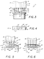
- Insertion of the conductive elements 18 of the connector member 12 into the complementary receptacles 26 of the receptacle member 20 operates to move the planar surface 24 into engagement with the laterally extending ends 34A and 34B so as to break their electrical connection with conductive elements or pins 18A and 18B, respectively, and thereafter move their respective arm portions 32A and 32B against the force of their inherent resilient spring bias toward the planar surface 16 of the electrical connector member 12.
- the inherent resilient spring biased arm portions 32A and 32B are substantially flattened between the planar surface 16 of the electrical connector 12 and the planar surface 24 of the receptacle member 20 so as to be out of electrical contact with any of the conductive elements or pins 18.
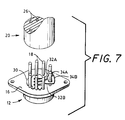
- the number of conductive elements of the connector member 12 to be shorted by the shorting member 28 is not just limited to the opposing pins 18A and 18B as shown at FIGS. 1 - 3 but may also include adjacent pins as shown in the embodiment of FIG. 7 where like numerals designate previously described elements.
- the shorting member 28 is not limited to having only two shorting arm portions but may have any select number of arm portions extending past respective corresponding conductive elements so as to effectively short any select number of conductive elements upon disconnection of the connector member from the receptacle member.
- the shorting member 28 may comprise any metallized foil and may be fixedly connected with respect to the planar surface 16 of the connector member 12 by any conventional means such as a suitable adhesive or by tack welding.
- FIGS. 4 - 6 where like numerals designate previously described elements, there is shown an alternate embodiment for the electrical connector and receptacle assembly 10′ of this invention.
- the plurality of elongated conductive elements or pins 18 are arranged in linear spaced apart relationship with respect to each other.
- the connector member 12′ further comprises a rectangularly shaped housing 14′ having a substantially planar surface 16′ and a plurality of depending side surfaces 36′ substantially orthogonal to the planar surface 16′.
- the shorting member as shown generally at 28′ comprises two overlapping thin conductive sheets each having base portions 30′ and 30 ⁇ , respectively, fixedly connected in contiguous relationship with respect to each other and the side surface 36′.
- an arm portion 32′ which extends past the conductive elements or pins 18A, 18B and 18C with the laterally extending end 34′ thereof engaging a side of the conductive element or pin 18A.
- a second arm portion 32 ⁇ extending past the conductive element or pin 18C with the laterally extending end portion 34 ⁇ thereof electrically contacting a select side of the conductive element or pin 18C.
- the laterally extending end portions 34′ and 34 ⁇ of the spring biased arm portions 32′ and 32 ⁇ engage respectively the conductive elements or pins 18A and 18C so as to create an electrical short by way of the contacting base portions 30′ and 30 ⁇ .
- Insertion of the conductive elements or pins 18 of the connector member 12 into the complementary receptacles 26′ of the receptacle member 20′ operate to move the planar surface 24′ of the receptacle member 20′ into engagement with the laterally extending portions 34′ and 34 ⁇ so as to break the electrical connection to their respective conductive elements or pins 18A and 18C.
- Complete insertion of the connector member 12′ with respect to the receptacle member 20′ operates to substantially flatten the arm portions 32′ and 32 ⁇ of the shorting member 28′ between the planar surfaces 16′ and 24′ thereby electrically disconnecting the short between the conductive elements or pins 18A and 18C.
Landscapes
- Details Of Connecting Devices For Male And Female Coupling (AREA)
- Coupling Device And Connection With Printed Circuit (AREA)
- Multi-Conductor Connections (AREA)
Claims (8)
- Connecteur électrique comprenant:
une partie connecteur (12) définissant une surface sensiblement plane (16);
une pluralité d'éléments conducteurs allongés (18) s'étendant depuis ladite surface plane (16) dans une disposition mutuelle où ils sont sensiblement parallèles et espacés les uns par rapport aux autres, et
un organe de court-circuitage,
caractérisé en ce que l'organe de court-circuitage comprend une mince feuille conductrice comportant une partie base (30) montée de façon fixe par rapport à la partie connecteur précitée (12) dans une disposition espacée par rapport à chacun desdits éléments conducteurs allongés (18) et une pluralité de minces parties bras allongées (32A, 32B) faisant corps chacune à une de leurs extrémités avec ladite partie base (30) et, s'étendant en porte-à-faux depuis cette dernière de manière à se prolonger au-delà d'au moins un élément correspondant desdits éléments conducteurs allongés (18), l'autre extrémité de chacune desdites parties bras (34A, 34B) s'étendant latéralement vers l'extérieur de manière à se trouver en contact électrique avec un côté choisi de cet élément conducteur allongé (12) au-delà duquel cette partie bras (34A, 34B) s'étend, chaque partie bras précitée (32A, 32B) présentant une force élastique de sollicitation inhérente de manière à pousser cette dite autre extrémité (34A, 34B), s'étendant latéralement, pour qu'elle s'éloigne de ladite surface plane (16) et vienne en contact électrique avec ledit côté choisi de cet élément conducteur allongé (18) au-delà duquel, cette partie bras (34A, 34B) s'étend. - Connecteur électrique selon la revendication 1, dans lequel: lesdits éléments conducteurs allongés (18) sont placés dans une position linéaire où ils sont espacés les uns des autres, une première desdites parties bras (32′) s'étend au-delà d'au moins deux desdits éléments conducteurs allongés (18) espacés linéairement les uns des autres, et ladite autre extrémité de ladite première partie bras s'étend latéralement vers l'extérieur de manière à être sollicitée élastiquement pour venir en contact électrique avec ledit côté choisi de l'élément conducteur allongé (18) au-delà duquel 10 ladite première partie bras s'étend, et une seconde desdites parties bras (32˝) recouvre ladite première partie bras (32′) et s'étend au-delà d'au moins un desdits éléments conducteurs allongés (18) espacés les uns des autres linéairement mais pas au-delà de l'élément conducteur allongé (18) au-delà duquel ladite première desdites parties bras (32′) s'étend et ladite autre extrémité de ladite seconde partie bras (32˝) s'étend latéralement vers l'extérieur de manière à être sollicitée élastiquement élastiquement pour venir en contact électrique avec ledit côté choisi de l'élément conducteur allongé (18) au-delà duquel ladite seconde partie bras (32˝) s'étend.
- Connecteur électrique selon la revendication 2 dans lequel: ladite partie connecteur (12′) comprend un boîtier comportant une première surface qui définit ladite surface plane (16′) à partir de laquelle lesdits éléments conducteurs allongés (18) s'étendent et une pluralité de surfaces latérales (14′) s'étendant vers le bas et sensiblement orthogonales à ladite première surface (16′); et ladite partie base (30) dudit organe de court-circuitage est montée de façon fixe par rapport à une surface choisie desdites surfaces latérales (14′).
- Connecteur électrique selon la revendication 1, dans lequel lesdits éléments conducteurs allongés (18) sont disposés de façon circonférentielle en étant espacés les uns des autres, ladite partie base (30) dudit organe de court-circuitage est montée de façon fixe à l'intérieur de la zone délimitée par lesdits éléments conducteurs allongés (18) espacés circonférentiellement les uns des autres; une première (32A) desdites parties bras s'étend depuis ladite zone délimitée par lesdits éléments conducteurs allongés (18) espacés circonférentiellement les uns des autres au-delà d'un premier desdits éléments conducteurs allongés (18) et ladite autre extrémité de ladite première partie bras (32A) s'étend latéralement vers l'extérieur de manière à être sollicitée élastiquement pour venir en contact électrique avec ledit côté choisi dudit premier élément conducteur allongé (18); et une seconde desdites parties bras (32B) s'étend depuis ladite zone délimitée par lesdits éléments conducteurs allongés (18) espacés circonférentiellement les uns des autres au-delà d'un second desdits éléments conducteurs allongés (18) et ladite autre extrémité (34B) de ladite seconde partie bras s'étend latéralement vers l'extérieur de manière à être sollicitée élastiquement pour venir en contact électrique avec ledit côté choisi dudit second élément conducteur allongé (18).
- Ensemble électrique de connecteur et de réceptacle comprenant:
une partie connecteur (12) définissant une première surface sensiblement plane (16);
une pluralité d'éléments conducteurs allongés (18) s'étendant vers l'extérieur depuis ladite première surface plane (16) dans une disposition mutuelle où ils sont isolés, espacés et sensiblement parallèles les uns par rapport aux autres;
une partie réceptacle (20) définissant une seconde surface sensiblement plane (24);
une pluralité de réceptacles allongés (26) s'étendant vers l'intérieur depuis ladite seconde surface plane (24) dans une disposition mutuelle où ils sont isolés, espacés et sensiblement parallèles les uns par rapport aux autres et dans une disposition complémentaire vis-à-vis desdits éléments conducteurs allongés (18) pour permettre l'insertion desdits éléments conducteurs allongés (18) dans les réceptacles respectifs desdits réceptacles (26); et
un organe de court-circuitage comprenant une mince feuille conductrice comportant une partie base (30) montée de façon fixe par rapport à ladite partie connecteur (12) et espacée de chacun desdits éléments conducteurs allongés (18), et une pluralité de minces parties bras allongées (32A, 32B) faisant corps chacune à une de leurs extrémités à ladite partie base (30) et s'étendant en porte-à-faux depuis cette dernière de manière à se prolonger au-delà d'au moins un élément respectif desdits éléments conducteurs allongés (18), l'autre extrémité de chacune desdites parties bras (34A, 34B) s'étendant latéralement vers l'extérieur de manière à être en contact électrique avec un côté choisi de l'élément conducteur allongé (18) au-delà duquel ladite partie bras s'étend, chaque partie bras précitée présentant une force élastique de sollicitation inhérente de manière à pousser ladite autre extrémité (34A, 34B) s'étendant latéralement pour qu'elle s'éloigne de ladite première surface plane (16) et vienne en contact électrique avec ledit côté choisi de l'élément conducteur allongé (18) au-delà duquel cette partie bras s'étend, l'insertion des éléments conducteurs allongés (18) de ladite partie connecteur (12) dans les réceptacles complémentaires (26) de ladite partie réceptacle (20) ayant pour effet d'amener ladite seconde surface plane (24) de ladite partie réceptacle (20) en contact avec les autres extrémités (34A, 34B) qui s'étendent latéralement et que comportent lesdites parties bras de manière à dévier dévier lesdites parties bras, à l'encontre de leur force de sollicitation élastique inhérente, en direction de ladite première surface (16) et hors de contact électrique avec ceux respectifs desdits éléments conducteurs allongés (18). - Ensemble selon la revendication 5 dans lequel: lesdits éléments conducteurs allongés (18) et lesdits réceptacles complémentaires sont disposés de façon espacée linéairement les uns des autres; une première (32′) desdites parties bras s'étend au-delà d'au moins deux desdits éléments conducteurs allongés (18′) espacés linéairement les uns des autres et ladite autre extrémité (34′) de ladite première partie bras (32′) s′étend latéralement vers l'extérieur de manière à être sollicitée élastiquement pour venir en contact électrique avec ledit côté choisi de l'élément conducteur allongé (18′) au-delà duquel ladite première partie bras (32′) s'étend; une seconde (32˝) desdites parties bras recouvre ladite première partie bras (32′) et s'étend au-delà d'au moins un desdits éléments allongés conducteurs (18) espacés linéairement les uns des autres, mais non pas au-delà de l'élément conducteur allongé (18′) au-delà duquel ladite première (32′) desdites parties bras s'étend et ladite autre extrémité (34˝) de ladite seconde partie bras (32′) s'étend latéralement vers l'extérieur de manière à être sollicitée élastiquement pour venir en contact électrique avec ledit côté choisi de l'élément conducteur allongé (18′) au-delà duquel ladite seconde partie bras (32˝) s'étend; et l'insertion des éléments conducteurs allongés (18′) de ladite partie connecteur (12′) dans les réceptacles complémentaires (26′) de ladite partie réceptacle (20′) a pour effet d'amener ladite seconde surface plane (24′) de ladite partie réceptacle (20′) en contact avec les autres extrémités (34', 34˝) qui s'étendent latéralement et que comportent lesdites première et seconde parties bras (32', 32˝) de manière à dévier lesdites parties bras (32', 32˝) à l'encontre de leur force élastique de sollicitation inhérente, en direction de ladite première surface plane (16′) et hors de contact électrique avec ceux respectifs desdits éléments conducteurs allongés (18).
- Ensemble selon la revendication 6, dans lequel: ladite partie connecteur (12′) comprend un boîtier comportant une première surface qui définit ladite surface plane (16′) à partir de laquelle lesdits éléments conducteurs allongés (18) s'étendent et une pluralité de surfaces latérales (14′) s'étendant vers le bas, de façon sensiblement orthogonales par rapport à ladite première surface (16′); et ladite partie base (30′) dudit organe de court-circuitage est montée de façon fixe par rapport à celle choisie desdites surfaces latérales (14′).
- Ensemble selon la revendication 5, dans lequel lesdits éléments conducteurs allongés (18′) et lesdits réceptacles complémentaires (26) sont disposés circonférentiellement en étant espacés les uns des autres; ladite partie base (30) dudit organe de court-circuitage est montée de façon fixe à l'intérieur de la zone délimitée par lesdits éléments conducteurs allongés (18) espacés circonférentiellement les uns des autres; une première (32A) desdites parties bras s'étend depuis ladite zone délimitée par lesdits éléments conducteurs allongés (18) espacés circonférentiellement les uns des autres, au-delà d'un premier desdits éléments conducteurs allongés (18) et ladite autre extrémité (34A) de ladite première partie bras (32A) s'étend latéralement vers l'extérieur de manière à être sollicitée élastiquement pour venir en contact électrique avec ledit côté choisi dudit premier élément conducteur allongé (18); une seconde desdites parties bras (32B) s'étend depuis ladite zone délimitée par lesdits éléments conducteurs allongés (18) espacés circonférentiellement les uns des autres au-delà d'un second desdits éléments conducteurs allongés (18) et ladite autre extrémité (34B) de ladite seconde partie bras (32B) s'étend latéralement vers l'extérieur de manière à être sollicitée élastiquement pour venir en contact électrique avec ledit côté choisi dudit second élément conducteur allongé (18); et, l'insertion des éléments conducteurs allongés (18) dudit élément connecteur (12) dans les réceptacles complémentaires (26) de ladite partie réceptacle (20) a pour effet d'amener ladite seconde surface plane (24) de ladite partie réceptacle (20) en contact avec les autres extrémités (34A, 34B) qui s'étendent latéralement et que comportent lesdites première et seconde parties bras (32A, 32B) de manière à dévier lesdites parties bras (32A, 32B) à l'encontre de leur force élastique de sollicitation inhérente, en direction de ladite première surface plane (16) et hors de contact électrique avec lesdits premier et second éléments conducteurs allongés (18), respectivement.
Applications Claiming Priority (2)
| Application Number | Priority Date | Filing Date | Title |
|---|---|---|---|
| US448228 | 1989-12-11 | ||
| US07/448,228 US4971568A (en) | 1989-12-11 | 1989-12-11 | Electrical connector with attachment for automatically shorting select conductors upon disconnection of connector |
Publications (2)
| Publication Number | Publication Date |
|---|---|
| EP0432368A1 EP0432368A1 (fr) | 1991-06-19 |
| EP0432368B1 true EP0432368B1 (fr) | 1994-11-09 |
Family
ID=23779475
Family Applications (1)
| Application Number | Title | Priority Date | Filing Date |
|---|---|---|---|
| EP90116404A Expired - Lifetime EP0432368B1 (fr) | 1989-12-11 | 1990-08-27 | Connecteur électrique avec dispositif de court circuitage automatique de conducteurs sélectionnés lors de la déconnexion d'un connecteur |
Country Status (8)
| Country | Link |
|---|---|
| US (1) | US4971568A (fr) |
| EP (1) | EP0432368B1 (fr) |
| JP (1) | JPH088130B2 (fr) |
| AT (1) | ATE114080T1 (fr) |
| CA (1) | CA2021889A1 (fr) |
| DE (1) | DE69014082T2 (fr) |
| DK (1) | DK0432368T3 (fr) |
| ES (1) | ES2066920T3 (fr) |
Cited By (1)
| Publication number | Priority date | Publication date | Assignee | Title |
|---|---|---|---|---|
| US5653606A (en) * | 1994-11-18 | 1997-08-05 | The Whitaker Corporation | Electrical interconnection system having retention and shorting features |
Families Citing this family (20)
| Publication number | Priority date | Publication date | Assignee | Title |
|---|---|---|---|---|
| US5163850A (en) * | 1991-04-18 | 1992-11-17 | Polaroid Corporation | Electrostatic discharge protection devices for semiconductor chip packages |
| US5108299A (en) * | 1991-04-18 | 1992-04-28 | Polaroid Corporation | Electrostatic discharge protection devices for semiconductor chip packages |
| DE4118312C2 (de) * | 1991-06-04 | 1995-03-09 | Amphenol Tuchel Elect | Kontaktsatz für eine Kontaktzonen aufweisende Karte |
| JPH089915Y2 (ja) * | 1991-07-15 | 1996-03-21 | 日本航空電子工業株式会社 | スイッチ付きコネクタ |
| US5401180A (en) * | 1993-06-01 | 1995-03-28 | Itt Corporation | Connector shorting spring |
| US5490033A (en) * | 1994-04-28 | 1996-02-06 | Polaroid Corporation | Electrostatic discharge protection device |
| US5599205A (en) * | 1994-07-20 | 1997-02-04 | Polaroid Corporation | Electrostatic discharge protection device |
| US5583733A (en) * | 1994-12-21 | 1996-12-10 | Polaroid Corporation | Electrostatic discharge protection device |
| EP0734100B1 (fr) * | 1995-03-20 | 2003-05-07 | The Whitaker Corporation | Connecteur électrique avec une position finale assurée |
| US5609498A (en) * | 1995-09-19 | 1997-03-11 | Itt Corporation | Secure connector system |
| US5847914A (en) * | 1995-12-21 | 1998-12-08 | Polaroid Corporation | Electrostatic discharge protection device |
| US5697501A (en) * | 1995-12-21 | 1997-12-16 | Polaroid Corporation | Electrostatic discharge protection device |
| US5812357A (en) * | 1996-10-11 | 1998-09-22 | Polaroid Corporation | Electrostatic discharge protection device |
| US5877933A (en) * | 1997-04-16 | 1999-03-02 | Johansen; Arnold W. | Electrostatic discharge protection device for magnetoresistive head |
| US5963415A (en) * | 1997-07-05 | 1999-10-05 | Polaroid Corporation | Electrostatic discharge protection device |
| US6065985A (en) * | 1998-10-14 | 2000-05-23 | Berg Technology, Inc. | Modular jack with flexible shorting structure |
| US6835079B2 (en) * | 2002-05-23 | 2004-12-28 | Positronic Industries, Inc. | Electrical connector assembly with shorting member |
| US7354287B1 (en) | 2006-10-31 | 2008-04-08 | Caterpillar Inc. | Shorting connector |
| US7616421B2 (en) * | 2006-12-18 | 2009-11-10 | Caterpillar Inc. | Electrical interface system |
| US7789685B2 (en) * | 2006-12-18 | 2010-09-07 | Caterpillar Inc | Electrical shorting system |
Family Cites Families (10)
| Publication number | Priority date | Publication date | Assignee | Title |
|---|---|---|---|---|
| US2197426A (en) * | 1936-11-05 | 1940-04-16 | Cinch Mfg Corp | Switch and radio tube socket assembly |
| US3467940A (en) * | 1967-03-17 | 1969-09-16 | William H Wallo | Electrical connecting spring device |
| US3600531A (en) * | 1970-05-08 | 1971-08-17 | Nat Tel Tronics Corp | Self-shorting phono plug |
| US3851944A (en) * | 1973-03-30 | 1974-12-03 | Okzona Inc | Current transformer connector |
| US4070557A (en) * | 1976-07-26 | 1978-01-24 | Northern Telecom Limited | Apparatus for providing closed loop conditions in vacant module positions |
| US4179178A (en) * | 1978-02-02 | 1979-12-18 | Rca Corporation | Plug-in circuit cartridge with electrostatic charge protection |
| USRE32760E (en) * | 1982-12-22 | 1988-10-04 | Amp Domestic Inc. | Electrical connector |
| US4699443A (en) * | 1984-12-28 | 1987-10-13 | American Telephone And Telegraph Company | Modular telephone jack |
| US4786258A (en) * | 1987-05-13 | 1988-11-22 | Amp Incorporated | Electrical connector with shunt |
| US4798542A (en) * | 1987-04-16 | 1989-01-17 | Amp Incorporated | Switching connector |
-
1989
- 1989-12-11 US US07/448,228 patent/US4971568A/en not_active Expired - Lifetime
-
1990
- 1990-07-24 CA CA002021889A patent/CA2021889A1/fr not_active Abandoned
- 1990-08-27 AT AT90116404T patent/ATE114080T1/de not_active IP Right Cessation
- 1990-08-27 EP EP90116404A patent/EP0432368B1/fr not_active Expired - Lifetime
- 1990-08-27 DE DE69014082T patent/DE69014082T2/de not_active Expired - Fee Related
- 1990-08-27 DK DK90116404.6T patent/DK0432368T3/da active
- 1990-08-27 ES ES90116404T patent/ES2066920T3/es not_active Expired - Lifetime
- 1990-10-23 JP JP2285715A patent/JPH088130B2/ja not_active Expired - Fee Related
Cited By (1)
| Publication number | Priority date | Publication date | Assignee | Title |
|---|---|---|---|---|
| US5653606A (en) * | 1994-11-18 | 1997-08-05 | The Whitaker Corporation | Electrical interconnection system having retention and shorting features |
Also Published As
| Publication number | Publication date |
|---|---|
| US4971568A (en) | 1990-11-20 |
| DE69014082T2 (de) | 1995-03-23 |
| ATE114080T1 (de) | 1994-11-15 |
| JPH03190070A (ja) | 1991-08-20 |
| CA2021889A1 (fr) | 1991-06-12 |
| ES2066920T3 (es) | 1995-03-16 |
| DK0432368T3 (da) | 1994-12-12 |
| EP0432368A1 (fr) | 1991-06-19 |
| JPH088130B2 (ja) | 1996-01-29 |
| DE69014082D1 (de) | 1994-12-15 |
Similar Documents
| Publication | Publication Date | Title |
|---|---|---|
| EP0432368B1 (fr) | Connecteur électrique avec dispositif de court circuitage automatique de conducteurs sélectionnés lors de la déconnexion d'un connecteur | |
| US5240430A (en) | Electrical connector for cable to circit board application | |
| US5164880A (en) | Electrostatic discharge protection device for a printed circuit board | |
| EP0772898B1 (fr) | Enveloppe de protection de mise a la terre amelioree pour connecteurs electriques | |
| EP0214830B1 (fr) | Connecteur pour un circuit imprimé flexible | |
| US6165017A (en) | Cable end connector | |
| US6315620B1 (en) | System, method, and device for a pre-loaded straddle mounted connector assembly | |
| US4870753A (en) | Method of manufacturing a light socket | |
| US6099335A (en) | Electrical card connector | |
| US4934943A (en) | Automated connector alignment assembly for connection of printed circuit boards | |
| US6109952A (en) | Terminal connector assembly | |
| US4237435A (en) | Ground fault receptacle re-set guide assembly | |
| US4731925A (en) | Method for providing a power connector | |
| EP0540260B1 (fr) | Connecteur électrique pour connecter une plaquette à circuits imprimés avec un câble | |
| US5186639A (en) | Electrical connector with plug detection switch | |
| US5425646A (en) | Printed circuit connector assembly | |
| US6457987B1 (en) | Plug connector with latch mechanism | |
| US4445742A (en) | Electrical cable connector | |
| US5266042A (en) | Electrical jack and patch plug assembly | |
| EP0213831A2 (fr) | Appareil de réception d'une lampe | |
| JPH09505438A (ja) | シャントコネクタ | |
| EP0354677B1 (fr) | Assemblage modulaire de conjoncteurs | |
| US4236128A (en) | Ground fault receptacle | |
| US4247840A (en) | Ground fault receptacle reversible conductors | |
| US6929510B2 (en) | Electrical connector with shielding plate |
Legal Events
| Date | Code | Title | Description |
|---|---|---|---|
| PUAI | Public reference made under article 153(3) epc to a published international application that has entered the european phase |
Free format text: ORIGINAL CODE: 0009012 |
|
| AK | Designated contracting states |
Kind code of ref document: A1 Designated state(s): AT BE CH DE DK ES FR GB GR IT LI LU NL SE |
|
| 17P | Request for examination filed |
Effective date: 19911206 |
|
| 17Q | First examination report despatched |
Effective date: 19931130 |
|
| GRAA | (expected) grant |
Free format text: ORIGINAL CODE: 0009210 |
|
| AK | Designated contracting states |
Kind code of ref document: B1 Designated state(s): AT BE CH DE DK ES FR GB GR IT LI LU NL SE |
|
| REF | Corresponds to: |
Ref document number: 114080 Country of ref document: AT Date of ref document: 19941115 Kind code of ref document: T |
|
| ET | Fr: translation filed | ||
| REG | Reference to a national code |
Ref country code: DK Ref legal event code: T3 |
|
| REF | Corresponds to: |
Ref document number: 69014082 Country of ref document: DE Date of ref document: 19941215 |
|
| EAL | Se: european patent in force in sweden |
Ref document number: 90116404.6 |
|
| ITF | It: translation for a ep patent filed | ||
| REG | Reference to a national code |
Ref country code: ES Ref legal event code: FG2A Ref document number: 2066920 Country of ref document: ES Kind code of ref document: T3 |
|
| REG | Reference to a national code |
Ref country code: GR Ref legal event code: FG4A Free format text: 3014831 |
|
| PLBE | No opposition filed within time limit |
Free format text: ORIGINAL CODE: 0009261 |
|
| STAA | Information on the status of an ep patent application or granted ep patent |
Free format text: STATUS: NO OPPOSITION FILED WITHIN TIME LIMIT |
|
| 26N | No opposition filed | ||
| REG | Reference to a national code |
Ref country code: GB Ref legal event code: IF02 |
|
| PGFP | Annual fee paid to national office [announced via postgrant information from national office to epo] |
Ref country code: DK Payment date: 20030715 Year of fee payment: 14 Ref country code: CH Payment date: 20030715 Year of fee payment: 14 |
|
| PGFP | Annual fee paid to national office [announced via postgrant information from national office to epo] |
Ref country code: NL Payment date: 20030718 Year of fee payment: 14 |
|
| PGFP | Annual fee paid to national office [announced via postgrant information from national office to epo] |
Ref country code: SE Payment date: 20030722 Year of fee payment: 14 Ref country code: GR Payment date: 20030722 Year of fee payment: 14 |
|
| PGFP | Annual fee paid to national office [announced via postgrant information from national office to epo] |
Ref country code: LU Payment date: 20030728 Year of fee payment: 14 |
|
| PGFP | Annual fee paid to national office [announced via postgrant information from national office to epo] |
Ref country code: BE Payment date: 20030801 Year of fee payment: 14 Ref country code: AT Payment date: 20030801 Year of fee payment: 14 |
|
| PGFP | Annual fee paid to national office [announced via postgrant information from national office to epo] |
Ref country code: ES Payment date: 20030811 Year of fee payment: 14 |
|
| PGFP | Annual fee paid to national office [announced via postgrant information from national office to epo] |
Ref country code: FR Payment date: 20040708 Year of fee payment: 15 |
|
| PGFP | Annual fee paid to national office [announced via postgrant information from national office to epo] |
Ref country code: GB Payment date: 20040712 Year of fee payment: 15 |
|
| PGFP | Annual fee paid to national office [announced via postgrant information from national office to epo] |
Ref country code: DE Payment date: 20040716 Year of fee payment: 15 |
|
| PG25 | Lapsed in a contracting state [announced via postgrant information from national office to epo] |
Ref country code: LU Free format text: LAPSE BECAUSE OF NON-PAYMENT OF DUE FEES Effective date: 20040827 Ref country code: AT Free format text: LAPSE BECAUSE OF NON-PAYMENT OF DUE FEES Effective date: 20040827 |
|
| PG25 | Lapsed in a contracting state [announced via postgrant information from national office to epo] |
Ref country code: SE Free format text: LAPSE BECAUSE OF NON-PAYMENT OF DUE FEES Effective date: 20040828 Ref country code: ES Free format text: LAPSE BECAUSE OF NON-PAYMENT OF DUE FEES Effective date: 20040828 |
|
| PG25 | Lapsed in a contracting state [announced via postgrant information from national office to epo] |
Ref country code: LI Free format text: LAPSE BECAUSE OF NON-PAYMENT OF DUE FEES Effective date: 20040831 Ref country code: DK Free format text: LAPSE BECAUSE OF NON-PAYMENT OF DUE FEES Effective date: 20040831 Ref country code: CH Free format text: LAPSE BECAUSE OF NON-PAYMENT OF DUE FEES Effective date: 20040831 Ref country code: BE Free format text: LAPSE BECAUSE OF NON-PAYMENT OF DUE FEES Effective date: 20040831 |
|
| BERE | Be: lapsed |
Owner name: *POLAROID CORP. Effective date: 20040831 |
|
| PG25 | Lapsed in a contracting state [announced via postgrant information from national office to epo] |
Ref country code: NL Free format text: LAPSE BECAUSE OF NON-PAYMENT OF DUE FEES Effective date: 20050301 |
|
| PG25 | Lapsed in a contracting state [announced via postgrant information from national office to epo] |
Ref country code: GR Free format text: LAPSE BECAUSE OF NON-PAYMENT OF DUE FEES Effective date: 20050303 |
|
| EUG | Se: european patent has lapsed | ||
| REG | Reference to a national code |
Ref country code: CH Ref legal event code: PL |
|
| NLV4 | Nl: lapsed or anulled due to non-payment of the annual fee |
Effective date: 20050301 |
|
| REG | Reference to a national code |
Ref country code: DK Ref legal event code: EBP |
|
| PG25 | Lapsed in a contracting state [announced via postgrant information from national office to epo] |
Ref country code: IT Free format text: LAPSE BECAUSE OF NON-PAYMENT OF DUE FEES;WARNING: LAPSES OF ITALIAN PATENTS WITH EFFECTIVE DATE BEFORE 2007 MAY HAVE OCCURRED AT ANY TIME BEFORE 2007. THE CORRECT EFFECTIVE DATE MAY BE DIFFERENT FROM THE ONE RECORDED. Effective date: 20050827 Ref country code: GB Free format text: LAPSE BECAUSE OF NON-PAYMENT OF DUE FEES Effective date: 20050827 |
|
| REG | Reference to a national code |
Ref country code: ES Ref legal event code: FD2A Effective date: 20040828 |
|
| PG25 | Lapsed in a contracting state [announced via postgrant information from national office to epo] |
Ref country code: DE Free format text: LAPSE BECAUSE OF NON-PAYMENT OF DUE FEES Effective date: 20060301 |
|
| GBPC | Gb: european patent ceased through non-payment of renewal fee |
Effective date: 20050827 |
|
| PG25 | Lapsed in a contracting state [announced via postgrant information from national office to epo] |
Ref country code: FR Free format text: LAPSE BECAUSE OF NON-PAYMENT OF DUE FEES Effective date: 20060428 |
|
| REG | Reference to a national code |
Ref country code: FR Ref legal event code: ST Effective date: 20060428 |
|
| BERE | Be: lapsed |
Owner name: *POLAROID CORP. Effective date: 20040831 |