EP0432458A2 - Couches adhésives distribuées selon une image pour l'impression - Google Patents
Couches adhésives distribuées selon une image pour l'impression Download PDFInfo
- Publication number
- EP0432458A2 EP0432458A2 EP90121435A EP90121435A EP0432458A2 EP 0432458 A2 EP0432458 A2 EP 0432458A2 EP 90121435 A EP90121435 A EP 90121435A EP 90121435 A EP90121435 A EP 90121435A EP 0432458 A2 EP0432458 A2 EP 0432458A2
- Authority
- EP
- European Patent Office
- Prior art keywords
- developer material
- image
- adhesive
- developer
- xerographic marking
- Prior art date
- Legal status (The legal status is an assumption and is not a legal conclusion. Google has not performed a legal analysis and makes no representation as to the accuracy of the status listed.)
- Granted
Links
Images




Classifications
-
- G—PHYSICS
- G03—PHOTOGRAPHY; CINEMATOGRAPHY; ANALOGOUS TECHNIQUES USING WAVES OTHER THAN OPTICAL WAVES; ELECTROGRAPHY; HOLOGRAPHY
- G03G—ELECTROGRAPHY; ELECTROPHOTOGRAPHY; MAGNETOGRAPHY
- G03G13/00—Electrographic processes using a charge pattern
- G03G13/06—Developing
- G03G13/10—Developing using a liquid developer, e.g. liquid suspension
-
- G—PHYSICS
- G03—PHOTOGRAPHY; CINEMATOGRAPHY; ANALOGOUS TECHNIQUES USING WAVES OTHER THAN OPTICAL WAVES; ELECTROGRAPHY; HOLOGRAPHY
- G03G—ELECTROGRAPHY; ELECTROPHOTOGRAPHY; MAGNETOGRAPHY
- G03G13/00—Electrographic processes using a charge pattern
- G03G13/01—Electrographic processes using a charge pattern for multicoloured copies
- G03G13/013—Electrographic processes using a charge pattern for multicoloured copies characterised by the developing step, e.g. the properties of the colour developers
-
- G—PHYSICS
- G03—PHOTOGRAPHY; CINEMATOGRAPHY; ANALOGOUS TECHNIQUES USING WAVES OTHER THAN OPTICAL WAVES; ELECTROGRAPHY; HOLOGRAPHY
- G03G—ELECTROGRAPHY; ELECTROPHOTOGRAPHY; MAGNETOGRAPHY
- G03G13/00—Electrographic processes using a charge pattern
- G03G13/14—Transferring a pattern to a second base
- G03G13/16—Transferring a pattern to a second base of a toner pattern, e.g. a powder pattern
-
- G—PHYSICS
- G03—PHOTOGRAPHY; CINEMATOGRAPHY; ANALOGOUS TECHNIQUES USING WAVES OTHER THAN OPTICAL WAVES; ELECTROGRAPHY; HOLOGRAPHY
- G03G—ELECTROGRAPHY; ELECTROPHOTOGRAPHY; MAGNETOGRAPHY
- G03G9/00—Developers
- G03G9/08—Developers with toner particles
- G03G9/09—Colouring agents for toner particles
-
- G—PHYSICS
- G03—PHOTOGRAPHY; CINEMATOGRAPHY; ANALOGOUS TECHNIQUES USING WAVES OTHER THAN OPTICAL WAVES; ELECTROGRAPHY; HOLOGRAPHY
- G03G—ELECTROGRAPHY; ELECTROPHOTOGRAPHY; MAGNETOGRAPHY
- G03G13/00—Electrographic processes using a charge pattern
- G03G13/01—Electrographic processes using a charge pattern for multicoloured copies
- G03G13/013—Electrographic processes using a charge pattern for multicoloured copies characterised by the developing step, e.g. the properties of the colour developers
- G03G13/0131—Electrographic processes using a charge pattern for multicoloured copies characterised by the developing step, e.g. the properties of the colour developers developing using a step for liquid development, e.g. plural liquid color developers
Definitions
- the present invention relates to the field of xerography wherein an electrostatic latent image is formed upon an image receptor surface and is subsequently made visible with colored marking particles. More particularly, this invention relates to the use of a developer material comprising colorless adhesive particles to which colored marking particles are applied.
- xerography is used to denote any imaging process wherein there is formed a pattern of electrostatic charges upon an image receptor.
- electrostatic latent image a uniform electrostatic charge is placed on a photoconductive insulating layer known as a photoreceptor, the photoreceptor is then exposed to a projected image of light and shadow whereby the surface charge on the areas exposed to light is dissipated, leaving an image-wise pattern of charges on the photoreceptor, known as an electrostatic latent image.
- laser xerography a uniformly charged photoreceptor is discharged by the selective projection of a laser light source thereon, leaving a charge pattern on the photoreceptor.
- ionography charged particles (air ions) are directly deposited, in an imagewise pattern, upon a conductively backed dielectric surface, known as a charge receptor.
- the electrostatic latent image is then developed, i.e. made visible, by the application of a finely divided particulate colorant, known as toner, in either powder or liquid form.
- the resultant developed image may then be transferred to a substrate, such as paper, and may be permanently affixed thereto by heat, pressure, a combination of heat and pressure, or other suitable fixing means such as solvent or overcoating treatment.
- the finely divided pigmented particles are brought into the vicinity of the electrostatic latent image by a transport mechanism, and will be attracted the image if they themselves bear an electrostatic charge opposite to that of the image areas on the charged surface.
- the toner particles used in xerography must become electrically charged in some manner either prior to or during the developing process in order to insure efficient and complete development of the image.
- triboelectric charging i.e. the appearance of static charges on insulating materials due to contact or friction
- the finely divided particles suspended in a dielectric liquid become charged by virtue of their electrokinetic relationship with the surrounding liquid. Both of these particle charging phenomena are surface effects and are critically dependent upon traces of contamination and other factors affecting the nature of the surfaces involved.
- Electrostatic images can be developed with dry powders by a number of different techniques. For example, a powder cloud may be generated adjacent the charged surface or the powder simply may be poured over the surface to be developed. In carrying out these mechanical operations, triboelectrification occurs and some of the particles acquire an electrical charge opposite in polarity to that of the image and hence are held on the image. For better control of the development process, the toner powder is mixed with a much coarser, granular, carrier material, and the mixture is cascaded, i.e. caused to flow, over the charged surface. In brush development, a carrier brush of mechanical or magnetic form transports the toner across the image area while simultaneously giving the toner the proper electrical charge.
- the carrier material selected for use with a given toner powder material must produce a triboelectric charge on the surface of the toner powder particles opposite in polarity to that of the image to be developed.
- Liquid development is usually effected by immersing the charged surface in an insulating liquid containing toner particles suspended therein.
- a satisfactory powder developer material must have a number of attributes, some of which are: it should have a uniform chemical composition; it must be pulverizable or otherwise dispersible into fine particles and have a narrow optimum particle size distribution; it must have the proper color, color intensity and color density, and the proper transparency or opacity; it must be capable of accepting and retaining electrical charges of the correct sign; it should have no adverse effects on the environment nor should it adversely affect the charge receptor surface; it should have the proper characteristics for being fixed to a copy sheet, e.g.
- a melting point within the proper range for heat fixing or sufficient solubility for solvent vapor fixing; it should be easily cleaned from the image receptor without sticking or streaking; it should not agglomerate in storage; it should have an adequate shelf life: and, perhaps most important, it should be reproducible. If carrier particles are used with it to impart the proper triboelectric charge, the carriers must also be designed to satisfy exacting specifications.
- An ideal liquid developer would have many of the same attributes as toner powder, such as color, surface charge magnitude and polarity, shelf life and reproducibility. Additionally, it should have good dispersibility, have the ability to maintain stability in solution, and be self fixing upon evaporation of the liquid carrier.
- the liquid medium should have a high volume resistivity so that the rate of destruction of the electrostatic image is minimized, a high dielectric constant and a high vapor pressure for quick drying. It should also be nontoxic, odorless, have a high flash and boiling point (i.e. nonflammable), have no solvent action on toner, have a specific gravity equal to or greater than that of the dispersed toner, have no reaction with the charge receptor surface, and be compatible with additive control agents (e.g. fixing and charge control).
- additive control agents e.g. fixing and charge control
- the developing function i.e. attracting a properly charged material to the electrostatic latent image
- the coloring function i.e. attracting a properly charged material to the electrostatic latent image
- a xerographic marking apparatus including a charge receptor member, means for creating an electrostatic latent image on the charge receptor member, means for developing the electrostatic latent image for making it visible, and means for transfering and fixing the visible image onto a transfer sheet.
- the means for developing comprises first means for electrostatically depositing a colorless adhesive developer material upon the electrostatic latent image, and second means for coloring the colorless adhesive developer material.
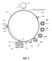
- Figure 1 is a schematic illustration of a xerographic machine configuration suitable for the process of the present invention
- Figure 2 is a schematic illustration of the xerographic machine of Figure 1 with an alternative development station
- Figure 3 is a schematic illustration of another xerographic machine configuration including an intermediate transfer member
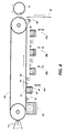
- Figure 4 is a schematic illustration of still another xerographic machine in a belt configuration for coloring with dyes
- Figure 5 is a schematic illustration of the Figure 4 embodiment modified by the introduction of an intermediate transfer member
- Figure 6 is a schematic illustration of another modification of the Figure 4 embodiment including an intermediate transfer member.
- an ionographic xerographic marking apparatus includes a charge receptor member 10 in the form of a metal drum bearing on its exterior surface a layer of a low surface energy dielectric material, such as Teflon® which is rotated in the direction indicated by arrow A.
- the charge receptor may also be in the form of an endless belt.
- An ionographic charge deposition head 12 extending the axial length of the drum 10 selectively projects charges of the appropriate sign onto the drum surface, in a line-by-line manner, through exit orifice 14 within which are ion stream modulating electrodes.
- the charges projected under process control form an electrostatic latent image of the information to be printed on the dielectric surface of the drum.
- the electrostatic latent image may be formed by electrophotography or laser xerography. Rotation of the charge receptor moves the latent image from the charging station through a development zone where the latent image may be made visible in the two-step development process which is the subject of the present invention.
- a colorless adhesive developer material is electrostatically attracted to the latent image
- colorant material is brought into contact with the adhesive imagewise pattern and is attached thereto.
- a liquid development station 16 including a sump 18 and an applicator roller 20 delivers the colorless adhesive developer particles to the drum surface.
- the developer particles used herein will be colorless and will exhibit adhesiveness or tackiness.
- brush applicator 26a is in a colorant dispensing mode while brush applicators 26b, 26c and 26d are in a non-dispensing mode.
- the arrows B indicate physical movement toward and away from the charge receptor they may be understood to represent also a gating mechanism within the applicator structure which selectively renders a stationary housing either operative or inoperative. Subsequent to the coloration step, any excess finely divided particulate colorant material adhering to the non-imaged, or background, areas of the charge receptor surface may beremoved aggressively by an air knife 28 or some other cleaning mechanism which will not disturb the developed image areas.
- this imaging apparatus may be used to produce monochrome images, it may produce a two color image comprising a primary color with highlight color, or it may be used to produce polychrome images being made up of several superimposed partial color images.
- each partial image is formed during a single rotation of the drum 10.
- the final image may be readily transferred and affixed to a suitable substrate, such as paper sheet 30 by a pressure roller 32.
- the adhesiveness of the developer material which is relied upon to attract and to retain the colorant material, should persist through image formation and may be used also to adhere the final image to the paper sheet.
- Transfer to the paper should be readily accomplished by the pressure applied by roller 32 and, if neccesary the further application of heat.
- the adhesive developer material will have a greater affinity for the paper and, if it is a multicolor image, for the other partial images in the image stack, than for the low surface energy material on the drum surface. Therefore, the entire image stack will preferentially adhere to the paper 30 rather than the drum 10.
- the electrostatic latent image is developed with the colorless adhesive developer material which in turn is colored with the desired colorant particles.
- the charge receptor 10 is moved past the charge deposition head 12 once for each partial latent image to be deposited and at each pass the correct colorant station 26 is made operative and the others are rendered inoperative. If the colorant step is carried to completion, i.e. fully loading the surface of the adhesive developer material with colorant particles, there will be no contamination of a preceding colored partial image by a subsequent one, because the surface of the adhesive developer layer will no longer be exposed and be able to accept colorant particles.
- the pressure roller 28 is movable toward and away from the charge receptor drum 10 (as indicated by arrow C) and will be moved to the drum surface only after the image is complete and transfer to sheet 30 is to be effected.
- a similar apparatus is shown with a powder developer applicator 34 for depositing the colorless adhesive developer material upon the image receptor.
- a brush applicator is schematically illustrated, any suitable mechanism may be utilized for transporting dry powder developer over the surface of the charge receptor. Dry powder developer materials, such as encapsulated adhesives, delayed tack adhesives or hot melt adhesives, are more easily applied to the electrostatic image if they are not in an adhesive state.
- an activator element 36 may be provided directly adjacent to the developer station. This element may take many forms. For example, if the developer particles comprise an adhesive material encapsulated in a rupturable shell, activator element 36 may be a pressure roller which will break open the shells.
- element 36 may take the form of a heat lamp or a lamp of the appropriate optical frequency.
- activator element could be an applicator roller to deliver solvent or a catalytic agent to tackify the developer particles.
- Other elements may be the same as that described with respect to the device of Figure 1.
- Either one or both of the moving processing surfaces may be in the form of drums, as shown, or in the form of endless belts.
- the developed colorless adhesive image will preferentially adhere to the latter and is transferred thereto in the nip 40 between these two elements.
- the final image stack will be transferred to substrate sheet 32 by means of pressure applied by pressure roller 30.
- Enhanced images may be formed with the arrangement shown in Figure 4.
- a charge receptor belt 42 has an electrostatic latent image formed thereon by charge deposition head 12 which image is developed at a liquid developer application station 44 where colorless adhesive developer material is attracted thereto. Immediately after emerging from the liquid development station 44, excess solvent is removed by an air knife 46.
- a liquid development station is shown, a powder development station may also be used.
- Colorant stations 48a, 48b, 48c and 48d are selectively made operative (note that station 48a is shown in dispensing position) to dispense a dye suspended in solution.
- Each colorant station comprises a liquid applicator 50 including a dispensing roller 52 immersed in a bath 54.
- the dye exists as independent molecules in solution.
- Dye colorants may readily be designed so as to be absorbed selectively into the particular adhesive developer material and not into the charge receptor surface.
- the solution holding the dye should be chosen to have an affinity for the adhesive developer, so that upon contact therewith it will cause the developer material to swell and to allow the solution and dye molecules to enter into its matrix.
- the charge receptor member 42 in the form of a thin metal belt with an appropriate low surface energy coating, the coating will not be affected by the dye during the coloration step. If some excess dye adheres slightly to the coating in the non-image areas, it can be readily removed by a suitable cleaning device, such as air knife 56.
- each partial color image is formed by first developing with the colorless adhesive developer and then coloring the developer.
- the partial images are deposited one upon the other. Since the previously applied partial developer image is capable of being colored by a subsequently applied dye, there is provided at colorant stations 48a to 48c a dye stop applicator 58 for applying an extremely thin layer of dye stop material, which establish a barrier over the previously colored partial image, and will prevent the developer from accepting subsequent dyes. Such an applicator will not be required at the final colorant station 48d since no subsequent dye is to be applied to the image.
- the dyed partial image adhesive layers may be made extremely thin so that the appearance of the final multicolor built-up image on the paper will have a more attractive appearance than the particulate colorant multicolor xerographic images. Also, since the absorption of dye into the adhesive developer layer should not affect its surface adhesiveness, its built-up layers will have a greater affinity for one another and for the paper surface than for the image receptor surface, and it should be possible to transfer the entire built-up image readily by the application of pressure. If desired a final, complete adhesive image may be developed to assist in the transfer step. In the event that the selected developer material is not tacky as developed, and needs to be made tacky in order to effect transfer, a heater 60 may be provided prior to the transfer station.
- This embodiment uniquely enables the production of continuous tone monochrome or full color images.
- the imagewise thickness of the colorless adhesive material will be proportional to the imagewise charge distribution of the electrostatic image, i.e. areas to be darker will have a greater charge density and will develop thicker. Since the dye actually migrates into the solid volume of the developer layer, if the coloration step is effected to completion, the optical density of the image (or partial image) will be proportional to the thickness of the developer layer.
- the electrostatic latent images also are formed on charge receptor 62 drum by charge deposition head 12.
- the latent images are then developed thereon, as by porous dispenser member 64, followed by the application of heat by heating element 66 for removing excess solvent and rendering the developed images tacky.
- the tackified developed adhesive images are transferred to intermediate, or holding member 68, upon which coloration takes place at stations 48a to 48d.
- the charge receptor member is reserved solely for development of the electrostatic charge images.
- FIG. 4 there is shown an alternative apparatus which eliminates the necessity of appling a dye stop.
- electrostatic latent images are formed on charge receptor belt 70 by charge deposition head 12, the images are developed with a colorless adhesive developer material (a liquid developer application station 72 is shown), excess solvent is removed by an air knife 74, and the developed images are made visible at dye colorant stations 48a, 48b, 48c and 48d.
- colorant materials are freed from the enormous number of compatibility constraints previously assigned to them.
- Color images can be achieved either additively or subtractively depending upon whether the colorants are opaque or colorless. Any colorant may be used, allowing precision in the representation of unique colors (such as those associated with company logos) as opposed to forming a unique, much used, color as a combination of basic colors.
- Color proofing devices may be made wherein the colorants used could be identical to those used in the actual printing inks. Images can be easily made from virtually any colorant material as needed for a specific function, such as insulating, conductive, magnetic, biological and mineral.
- the process of the present invention allows the known electrostatic transfer and heat fusing steps to be eliminated, thereby substantially lowering the cost of this device.
Landscapes
- Physics & Mathematics (AREA)
- General Physics & Mathematics (AREA)
- Color Electrophotography (AREA)
- Liquid Developers In Electrophotography (AREA)
- Wet Developing In Electrophotography (AREA)
- Developing Agents For Electrophotography (AREA)
- Combination Of More Than One Step In Electrophotography (AREA)
Applications Claiming Priority (2)
| Application Number | Priority Date | Filing Date | Title |
|---|---|---|---|
| US450698 | 1989-12-13 | ||
| US07/450,698 US5075186A (en) | 1989-12-13 | 1989-12-13 | Image-wise adhesion layers for printing |
Publications (3)
| Publication Number | Publication Date |
|---|---|
| EP0432458A2 true EP0432458A2 (fr) | 1991-06-19 |
| EP0432458A3 EP0432458A3 (en) | 1991-12-11 |
| EP0432458B1 EP0432458B1 (fr) | 1994-09-21 |
Family
ID=23789145
Family Applications (1)
| Application Number | Title | Priority Date | Filing Date |
|---|---|---|---|
| EP90121435A Expired - Lifetime EP0432458B1 (fr) | 1989-12-13 | 1990-11-08 | Couches adhésives distribuées selon une image pour l'impression |
Country Status (4)
| Country | Link |
|---|---|
| US (1) | US5075186A (fr) |
| EP (1) | EP0432458B1 (fr) |
| JP (1) | JP2609361B2 (fr) |
| DE (1) | DE69012762T2 (fr) |
Cited By (5)
| Publication number | Priority date | Publication date | Assignee | Title |
|---|---|---|---|---|
| WO1993007541A1 (fr) * | 1991-10-09 | 1993-04-15 | Spectrum Sciences B.V. | Amelioration des qualites de reflexion d'images |
| EP0636948A3 (fr) * | 1993-07-26 | 1996-02-07 | Hewlett Packard Co | Procédé et dispositif pour appliquer une couche adhésive pour le transfert d'images amélioré dans l'électrophotographie. |
| EP0692743A4 (fr) * | 1993-03-29 | 1997-02-12 | Fuji Photo Film Co Ltd | Procede et appareil de formation d'une image en couleur |
| WO1997012286A1 (fr) * | 1995-09-29 | 1997-04-03 | Minnesota Mining And Manufacturing Company | Procede et appareil presentant des caracteristiques de transfert d'image ameliorees pour produire une image sur un support recepteur tel que du papier non couche |
| EP0866377A1 (fr) * | 1997-03-19 | 1998-09-23 | Fujitsu Limited | Procédé de formation d'image et appareil |
Families Citing this family (35)
| Publication number | Priority date | Publication date | Assignee | Title |
|---|---|---|---|---|
| JP2953001B2 (ja) * | 1990-08-28 | 1999-09-27 | ミノルタ株式会社 | トナー供給装置 |
| US5702852A (en) * | 1995-08-31 | 1997-12-30 | Eastman Kodak Company | Multi-color method of toner transfer using non-marking toner and high pigment marking toner |
| US5737677A (en) * | 1995-08-31 | 1998-04-07 | Eastman Kodak Company | Apparatus and method of toner transfer using non-marking toner |
| US5794111A (en) * | 1995-12-14 | 1998-08-11 | Eastman Kodak Company | Apparatus and method of transfering toner using non-marking toner and marking toner |
| US5751268A (en) * | 1995-12-15 | 1998-05-12 | Xerox Corporation | Pseudo-four color twisting ball display |
| US5717514A (en) * | 1995-12-15 | 1998-02-10 | Xerox Corporation | Polychromal segmented balls for a twisting ball display |
| US5982346A (en) * | 1995-12-15 | 1999-11-09 | Xerox Corporation | Fabrication of a twisting ball display having two or more different kinds of balls |
| US5767826A (en) * | 1995-12-15 | 1998-06-16 | Xerox Corporation | Subtractive color twisting ball display |
| US5892497A (en) * | 1995-12-15 | 1999-04-06 | Xerox Corporation | Additive color transmissive twisting ball display |
| US6421035B1 (en) * | 1999-06-17 | 2002-07-16 | Xerox Corporation | Fabrication of a twisting ball display having two or more different kinds of balls |
| US5737115A (en) * | 1995-12-15 | 1998-04-07 | Xerox Corporation | Additive color tristate light valve twisting ball display |
| US5708525A (en) * | 1995-12-15 | 1998-01-13 | Xerox Corporation | Applications of a transmissive twisting ball display |
| US5739801A (en) * | 1995-12-15 | 1998-04-14 | Xerox Corporation | Multithreshold addressing of a twisting ball display |
| US5717515A (en) * | 1995-12-15 | 1998-02-10 | Xerox Corporation | Canted electric fields for addressing a twisting ball display |
| US5760761A (en) * | 1995-12-15 | 1998-06-02 | Xerox Corporation | Highlight color twisting ball display |
| US5926679A (en) * | 1997-12-08 | 1999-07-20 | Eastman Kodak Company | Method and apparatus for forming an image for transfer to a receiver sheet using a clear toner and sintering of a pigmented toner layer |
| US5976428A (en) * | 1998-01-09 | 1999-11-02 | Xerox Corporation | Method and apparatus for controlling formation of two-color balls for a twisting ball display |
| US5900192A (en) * | 1998-01-09 | 1999-05-04 | Xerox Corporation | Method and apparatus for fabricating very small two-color balls for a twisting ball display |
| US6440252B1 (en) | 1999-12-17 | 2002-08-27 | Xerox Corporation | Method for rotatable element assembly |
| US6545671B1 (en) | 2000-03-02 | 2003-04-08 | Xerox Corporation | Rotating element sheet material with reversible highlighting |
| US6498674B1 (en) | 2000-04-14 | 2002-12-24 | Xerox Corporation | Rotating element sheet material with generalized containment structure |
| US6504525B1 (en) | 2000-05-03 | 2003-01-07 | Xerox Corporation | Rotating element sheet material with microstructured substrate and method of use |
| US6847347B1 (en) | 2000-08-17 | 2005-01-25 | Xerox Corporation | Electromagnetophoretic display system and method |
| US6524500B2 (en) | 2000-12-28 | 2003-02-25 | Xerox Corporation | Method for making microencapsulated gyricon beads |
| US6690350B2 (en) | 2001-01-11 | 2004-02-10 | Xerox Corporation | Rotating element sheet material with dual vector field addressing |
| US6897848B2 (en) | 2001-01-11 | 2005-05-24 | Xerox Corporation | Rotating element sheet material and stylus with gradient field addressing |
| US6970154B2 (en) | 2001-01-11 | 2005-11-29 | Jpmorgan Chase Bank | Fringe-field filter for addressable displays |
| US6699570B2 (en) | 2001-11-06 | 2004-03-02 | Xerox Corporation | Colored cyber toner using multicolored gyricon spheres |
| US6930668B2 (en) * | 2003-01-15 | 2005-08-16 | Xerox Corporation | Color-enabled electrophoretic display and medium |
| US7046423B2 (en) * | 2003-01-15 | 2006-05-16 | Xerox Corporation | Separation of encapsulated particles from empty shells |
| GB0305856D0 (en) * | 2003-03-14 | 2003-04-16 | Qinetiq Ltd | Bistable display device |
| CA2519208A1 (fr) * | 2003-03-17 | 2004-09-30 | Takeda Pharmaceutical Company Limited | Composition a liberation controlee |
| JP5459612B2 (ja) * | 2009-04-16 | 2014-04-02 | 株式会社リコー | 画像形成装置 |
| US20120069113A1 (en) * | 2010-09-17 | 2012-03-22 | Toshiba Tec Kabushiki Kaisha | Image forming apparatus, medium processing apparatus, and image forming method |
| JP6164574B2 (ja) * | 2015-09-24 | 2017-07-19 | カシオ計算機株式会社 | 画像形成装置 |
Family Cites Families (4)
| Publication number | Priority date | Publication date | Assignee | Title |
|---|---|---|---|---|
| US3640746A (en) * | 1968-09-18 | 1972-02-08 | Xerox Corp | Adhesive contact electrification imaging |
| US4040828A (en) * | 1975-01-06 | 1977-08-09 | Xerox Corporation | Multicolor imaging method and imaged member employing combinations of transparent toner and colorant |
| US4368250A (en) * | 1977-05-23 | 1983-01-11 | Ani-Live Film Service Inc. | Dry transfer of electrophotographic images of an intumescent electroscopic thermoadhesive tower |
| US4464453A (en) * | 1980-01-16 | 1984-08-07 | Ani-Live Film Services, Inc. | Dry transfer carrier sheets for use in an electrophotographic process |
-
1989
- 1989-12-13 US US07/450,698 patent/US5075186A/en not_active Expired - Lifetime
-
1990
- 1990-11-08 DE DE69012762T patent/DE69012762T2/de not_active Expired - Fee Related
- 1990-11-08 EP EP90121435A patent/EP0432458B1/fr not_active Expired - Lifetime
- 1990-11-29 JP JP2336942A patent/JP2609361B2/ja not_active Expired - Fee Related
Cited By (7)
| Publication number | Priority date | Publication date | Assignee | Title |
|---|---|---|---|---|
| WO1993007541A1 (fr) * | 1991-10-09 | 1993-04-15 | Spectrum Sciences B.V. | Amelioration des qualites de reflexion d'images |
| EP0692743A4 (fr) * | 1993-03-29 | 1997-02-12 | Fuji Photo Film Co Ltd | Procede et appareil de formation d'une image en couleur |
| EP0636948A3 (fr) * | 1993-07-26 | 1996-02-07 | Hewlett Packard Co | Procédé et dispositif pour appliquer une couche adhésive pour le transfert d'images amélioré dans l'électrophotographie. |
| WO1997012286A1 (fr) * | 1995-09-29 | 1997-04-03 | Minnesota Mining And Manufacturing Company | Procede et appareil presentant des caracteristiques de transfert d'image ameliorees pour produire une image sur un support recepteur tel que du papier non couche |
| US5650253A (en) * | 1995-09-29 | 1997-07-22 | Minnesota Mining And Manufacturing Company | Method and apparatus having improved image transfer characteristics for producing an image on a receptor medium such as a plain paper |
| EP0866377A1 (fr) * | 1997-03-19 | 1998-09-23 | Fujitsu Limited | Procédé de formation d'image et appareil |
| US6004707A (en) * | 1997-03-19 | 1999-12-21 | Fujitsu Limited | Method and apparatus for forming image using an improved liquid developing technique |
Also Published As
| Publication number | Publication date |
|---|---|
| EP0432458A3 (en) | 1991-12-11 |
| EP0432458B1 (fr) | 1994-09-21 |
| JP2609361B2 (ja) | 1997-05-14 |
| US5075186A (en) | 1991-12-24 |
| DE69012762T2 (de) | 1995-02-09 |
| DE69012762D1 (de) | 1994-10-27 |
| JPH03189661A (ja) | 1991-08-19 |
Similar Documents
| Publication | Publication Date | Title |
|---|---|---|
| US5075186A (en) | Image-wise adhesion layers for printing | |
| US3013890A (en) | Process of developing electrostatic images and composition therefor | |
| AU2003217351B2 (en) | Method and apparatus for making signs having an adhesive | |
| US6137976A (en) | Image formation apparatus using a liquid developing agent | |
| US3574614A (en) | Process of preparing multiple copies from a xeroprinting master | |
| US4040828A (en) | Multicolor imaging method and imaged member employing combinations of transparent toner and colorant | |
| US4135925A (en) | Methods of changing color by image disruption | |
| WO2023069440A1 (fr) | Machine d'impression et plaque à motif fixe | |
| JPS62242977A (ja) | 静電荷像の電気泳動現像 | |
| US4230784A (en) | Electrostatic image forming process and particles comprising reactive sublimable dye, subliming developer and conductive substance | |
| US3676215A (en) | Imaging system | |
| US6219501B1 (en) | Method and apparatus for toner cake delivery | |
| JPH01302358A (ja) | 像形成部材 | |
| US3615394A (en) | Method of forming a pigment image from a pigment-resin toner image | |
| JPH08234614A (ja) | ストリークの除去工程を備えたカラー透明体定着装置および構造 | |
| US5561507A (en) | Apparatus and method for producing an electrostatic image using water-base toner | |
| JPH08305207A (ja) | 剥離剤の計量方法及び計量装置 | |
| US3415186A (en) | Duplicating system | |
| JPH07281499A (ja) | 逆符号の電荷のトナーを用いた電子写真画像形成システムおよび方法 | |
| US3748126A (en) | Multiple copy selective re wetting printing | |
| US6438332B2 (en) | Method and apparatus for toner cake delivery | |
| JP2610304B2 (ja) | 電界粘性インキを用いる記録装置 | |
| JP2707721B2 (ja) | 粉体像の転写方法 | |
| JPH11223997A (ja) | 液状現像剤を用いる撮像装置および撮像方法 | |
| JPH11202631A (ja) | 液状現像剤層を用いる撮像装置及び方法 |
Legal Events
| Date | Code | Title | Description |
|---|---|---|---|
| PUAI | Public reference made under article 153(3) epc to a published international application that has entered the european phase |
Free format text: ORIGINAL CODE: 0009012 |
|
| AK | Designated contracting states |
Kind code of ref document: A2 Designated state(s): DE FR GB |
|
| PUAL | Search report despatched |
Free format text: ORIGINAL CODE: 0009013 |
|
| AK | Designated contracting states |
Kind code of ref document: A3 Designated state(s): DE FR GB |
|
| 17P | Request for examination filed |
Effective date: 19920430 |
|
| 17Q | First examination report despatched |
Effective date: 19930709 |
|
| GRAA | (expected) grant |
Free format text: ORIGINAL CODE: 0009210 |
|
| AK | Designated contracting states |
Kind code of ref document: B1 Designated state(s): DE FR GB |
|
| REF | Corresponds to: |
Ref document number: 69012762 Country of ref document: DE Date of ref document: 19941027 |
|
| ET | Fr: translation filed | ||
| PLBE | No opposition filed within time limit |
Free format text: ORIGINAL CODE: 0009261 |
|
| STAA | Information on the status of an ep patent application or granted ep patent |
Free format text: STATUS: NO OPPOSITION FILED WITHIN TIME LIMIT |
|
| 26N | No opposition filed | ||
| REG | Reference to a national code |
Ref country code: GB Ref legal event code: IF02 |
|
| PGFP | Annual fee paid to national office [announced via postgrant information from national office to epo] |
Ref country code: GB Payment date: 20031105 Year of fee payment: 14 |
|
| PGFP | Annual fee paid to national office [announced via postgrant information from national office to epo] |
Ref country code: FR Payment date: 20031110 Year of fee payment: 14 |
|
| PGFP | Annual fee paid to national office [announced via postgrant information from national office to epo] |
Ref country code: DE Payment date: 20031120 Year of fee payment: 14 |
|
| PG25 | Lapsed in a contracting state [announced via postgrant information from national office to epo] |
Ref country code: GB Free format text: LAPSE BECAUSE OF NON-PAYMENT OF DUE FEES Effective date: 20041108 |
|
| PG25 | Lapsed in a contracting state [announced via postgrant information from national office to epo] |
Ref country code: DE Free format text: LAPSE BECAUSE OF NON-PAYMENT OF DUE FEES Effective date: 20050601 |
|
| GBPC | Gb: european patent ceased through non-payment of renewal fee |
Effective date: 20041108 |
|
| PG25 | Lapsed in a contracting state [announced via postgrant information from national office to epo] |
Ref country code: FR Free format text: LAPSE BECAUSE OF NON-PAYMENT OF DUE FEES Effective date: 20050729 |
|
| REG | Reference to a national code |
Ref country code: FR Ref legal event code: ST |