EP0432771B1 - Dreidimensionaler Ultraschallabtaster - Google Patents
Dreidimensionaler Ultraschallabtaster Download PDFInfo
- Publication number
- EP0432771B1 EP0432771B1 EP90124038A EP90124038A EP0432771B1 EP 0432771 B1 EP0432771 B1 EP 0432771B1 EP 90124038 A EP90124038 A EP 90124038A EP 90124038 A EP90124038 A EP 90124038A EP 0432771 B1 EP0432771 B1 EP 0432771B1
- Authority
- EP
- European Patent Office
- Prior art keywords
- scanner
- ultrasonic
- transducer unit
- transducer
- case
- Prior art date
- Legal status (The legal status is an assumption and is not a legal conclusion. Google has not performed a legal analysis and makes no representation as to the accuracy of the status listed.)
- Expired - Lifetime
Links
- 230000007246 mechanism Effects 0.000 claims description 12
- 230000008878 coupling Effects 0.000 claims description 8
- 238000010168 coupling process Methods 0.000 claims description 8
- 238000005859 coupling reaction Methods 0.000 claims description 8
- 239000012528 membrane Substances 0.000 claims description 8
- 238000005192 partition Methods 0.000 claims description 7
- 239000000463 material Substances 0.000 claims description 3
- 239000000725 suspension Substances 0.000 claims description 3
- 230000000694 effects Effects 0.000 claims description 2
- 230000002093 peripheral effect Effects 0.000 claims 1
- 239000011358 absorbing material Substances 0.000 description 5
- 238000003745 diagnosis Methods 0.000 description 4
- 238000010521 absorption reaction Methods 0.000 description 3
- 230000008901 benefit Effects 0.000 description 3
- 238000001514 detection method Methods 0.000 description 3
- 238000011161 development Methods 0.000 description 3
- 230000018109 developmental process Effects 0.000 description 3
- 210000000056 organ Anatomy 0.000 description 3
- 230000009471 action Effects 0.000 description 2
- 230000005540 biological transmission Effects 0.000 description 2
- 238000000034 method Methods 0.000 description 2
- 230000004044 response Effects 0.000 description 2
- 230000004075 alteration Effects 0.000 description 1
- 230000003321 amplification Effects 0.000 description 1
- 230000017531 blood circulation Effects 0.000 description 1
- 230000000052 comparative effect Effects 0.000 description 1
- 230000001419 dependent effect Effects 0.000 description 1
- 238000010586 diagram Methods 0.000 description 1
- 238000002592 echocardiography Methods 0.000 description 1
- 238000002474 experimental method Methods 0.000 description 1
- 230000006870 function Effects 0.000 description 1
- 239000007788 liquid Substances 0.000 description 1
- 238000003199 nucleic acid amplification method Methods 0.000 description 1
- 239000003921 oil Substances 0.000 description 1
- 229920002379 silicone rubber Polymers 0.000 description 1
- XLYOFNOQVPJJNP-UHFFFAOYSA-N water Substances O XLYOFNOQVPJJNP-UHFFFAOYSA-N 0.000 description 1
Images


Classifications
-
- A—HUMAN NECESSITIES
- A61—MEDICAL OR VETERINARY SCIENCE; HYGIENE
- A61B—DIAGNOSIS; SURGERY; IDENTIFICATION
- A61B8/00—Diagnosis using ultrasonic, sonic or infrasonic waves
- A61B8/42—Details of probe positioning or probe attachment to the patient
- A61B8/4272—Details of probe positioning or probe attachment to the patient involving the acoustic interface between the transducer and the tissue
- A61B8/4281—Details of probe positioning or probe attachment to the patient involving the acoustic interface between the transducer and the tissue characterised by sound-transmitting media or devices for coupling the transducer to the tissue
-
- A—HUMAN NECESSITIES
- A61—MEDICAL OR VETERINARY SCIENCE; HYGIENE
- A61B—DIAGNOSIS; SURGERY; IDENTIFICATION
- A61B8/00—Diagnosis using ultrasonic, sonic or infrasonic waves
- A61B8/13—Tomography
- A61B8/14—Echo-tomography
-
- A—HUMAN NECESSITIES
- A61—MEDICAL OR VETERINARY SCIENCE; HYGIENE
- A61B—DIAGNOSIS; SURGERY; IDENTIFICATION
- A61B8/00—Diagnosis using ultrasonic, sonic or infrasonic waves
- A61B8/44—Constructional features of the ultrasonic, sonic or infrasonic diagnostic device
- A61B8/4444—Constructional features of the ultrasonic, sonic or infrasonic diagnostic device related to the probe
- A61B8/4461—Features of the scanning mechanism, e.g. for moving the transducer within the housing of the probe
-
- A—HUMAN NECESSITIES
- A61—MEDICAL OR VETERINARY SCIENCE; HYGIENE
- A61B—DIAGNOSIS; SURGERY; IDENTIFICATION
- A61B8/00—Diagnosis using ultrasonic, sonic or infrasonic waves
- A61B8/44—Constructional features of the ultrasonic, sonic or infrasonic diagnostic device
- A61B8/4483—Constructional features of the ultrasonic, sonic or infrasonic diagnostic device characterised by features of the ultrasound transducer
-
- A—HUMAN NECESSITIES
- A61—MEDICAL OR VETERINARY SCIENCE; HYGIENE
- A61B—DIAGNOSIS; SURGERY; IDENTIFICATION
- A61B8/00—Diagnosis using ultrasonic, sonic or infrasonic waves
- A61B8/48—Diagnostic techniques
- A61B8/483—Diagnostic techniques involving the acquisition of a 3D volume of data
-
- G—PHYSICS
- G10—MUSICAL INSTRUMENTS; ACOUSTICS
- G10K—SOUND-PRODUCING DEVICES; METHODS OR DEVICES FOR PROTECTING AGAINST, OR FOR DAMPING, NOISE OR OTHER ACOUSTIC WAVES IN GENERAL; ACOUSTICS NOT OTHERWISE PROVIDED FOR
- G10K11/00—Methods or devices for transmitting, conducting or directing sound in general; Methods or devices for protecting against, or for damping, noise or other acoustic waves in general
- G10K11/18—Methods or devices for transmitting, conducting or directing sound
- G10K11/26—Sound-focusing or directing, e.g. scanning
- G10K11/34—Sound-focusing or directing, e.g. scanning using electrical steering of transducer arrays, e.g. beam steering
- G10K11/341—Circuits therefor
-
- G—PHYSICS
- G10—MUSICAL INSTRUMENTS; ACOUSTICS
- G10K—SOUND-PRODUCING DEVICES; METHODS OR DEVICES FOR PROTECTING AGAINST, OR FOR DAMPING, NOISE OR OTHER ACOUSTIC WAVES IN GENERAL; ACOUSTICS NOT OTHERWISE PROVIDED FOR
- G10K11/00—Methods or devices for transmitting, conducting or directing sound in general; Methods or devices for protecting against, or for damping, noise or other acoustic waves in general
- G10K11/18—Methods or devices for transmitting, conducting or directing sound
- G10K11/26—Sound-focusing or directing, e.g. scanning
- G10K11/35—Sound-focusing or directing, e.g. scanning using mechanical steering of transducers or their beams
- G10K11/352—Sound-focusing or directing, e.g. scanning using mechanical steering of transducers or their beams by moving the transducer
- G10K11/355—Arcuate movement
-
- Y—GENERAL TAGGING OF NEW TECHNOLOGICAL DEVELOPMENTS; GENERAL TAGGING OF CROSS-SECTIONAL TECHNOLOGIES SPANNING OVER SEVERAL SECTIONS OF THE IPC; TECHNICAL SUBJECTS COVERED BY FORMER USPC CROSS-REFERENCE ART COLLECTIONS [XRACs] AND DIGESTS
- Y10—TECHNICAL SUBJECTS COVERED BY FORMER USPC
- Y10S—TECHNICAL SUBJECTS COVERED BY FORMER USPC CROSS-REFERENCE ART COLLECTIONS [XRACs] AND DIGESTS
- Y10S128/00—Surgery
- Y10S128/916—Ultrasound 3-D imaging
Definitions
- the present invention relates to an ultrasonic scanner according to the preamble of claim 1, for transmitting/receiving ultrasonic beams and, more particularly, to an ultrasonic scanner capable of acquiring three-dimensional data concerning objects within a living body to be examined for a three-dimensional medical diagnosis use.
- the technique of ultrasonic diagnosis has been widely utilized.
- Such a medical diagnosis is performed by the use of an ultrasonic diagnostic apparatus composed of a mainframe of an ultrasonic diagnostic apparatus and a scanner including an array transducer.
- the diagnostic apparatus transmits ultrasonic beams and receives reflected echoes from objects in the living body by means of an ultrasonic scanner being in contact with a skin of the body, and thus acquired echo data are analyzed and processed by the mainframe of the diagnostic apparatus, so that the information of cross-sectional layer image and blood flow velocity, etc., are visually displayed in the form of a dynamic image.
- an array transducer 12 disposed inside of a convex-shaped end portion of the scanner effects the transmission and reception of an ultrasonic beam.
- this array transducer 12 is composed of a plurality of transducer elements 12a arranged along the end surface of the convex-shaped scanner 10.
- an acoustic lens 14 for focusing the ultrasonic beam
- a matching layer 16 for matching acoustic impedance is disposed between the acoustic lens 14 and the array transducer 12.
- a backing layer 18 is disposed behind of the array transducer 12 for absorbing unnecessary ultrasonic waves.
- each transducer element 12a With such a structure, the application of a drive signal to each transducer element 12a causes the ultrasonic beam to be transmitted in a direction normal to the upper surface of the element 12a. With this result, it becomes possible to acquire data concerning a fun-shaped two-dimensional area.
- a generic ultrasonic scanner is known from the DE-B-2826828 and comprises a transducer unit composed of an array of transducer elements. However, this scanner is only able to acquire quasi three-dimensional images.
- the transducer unit can be positioned in a rotational and translational direction by a positioning mechanism.
- the positioning mechanism according to the DE-B-2826828 it was achieved that the ultrasonic waves of the transducer array are directed to a certain point on an object to be examined, with the ultrasonic waves of a single transducer also impinging on this point.
- the mechanical positioning is performed only for reasons of adjusting, but not for reasons of data acquisition.
- the FR-A-2620327 discloses a scanner which is not able to obtain three-dimensional data.
- the FR-A-2620327 it was already possible to perform a scanning of an object to be examined by a mechanical swinging movement of a transducer, but only for obtaining two-dimensional data.
- the mechanical swinging of the transducer and its angle detection by an angle detector is, according to the invention, superposed with an electronic scanning by the transducer array in a normal direction with respect to each other to form a three-dimensional data acquisition area.
- the three-dimensional area is obtained within a body by specifying a position in three dimension without inclining the angle, or moving the position, of the scanner manually and intentionally.
- the transducer unit is swung in a direction normal to a direction in which a plurality of transducer elements are arranged, and the angle formed by this swing operation is concurrently detected by the angle detector.
- the data acquisition can be realized in a three-dimensional area by mechanically swinging the two-dimensional data acquisition plane constituted by the scanning of the array transducer, accurate and stable data acquisition can be realized independent of any manual and intentional operation.
- Another advantage of the invention is that since the three-dimensional position of the echo data is determined by an address of the transducer element to be driven and the swing angle, it becomes possible to supply the mainframe of the ultrasonic diagnostic apparatus with information as to the swing angle indispensable for executing the processing of three-dimensional images.
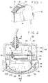
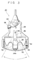
- Fig. 2 is a front sectional view of the three-dimensional scanner in accordance with one preferred embodiment of the invention.
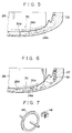
- Fig. 3 is a sectional view of the scanner shown in Fig. 2, taken along a dash-and-one-dot line III-III' shown therein.
- a scanner case 22 in which an ultrasonic scanner 20 is encased has a contact wall 24, which constitutes a bottom part of wall and is formed in a rather smooth convex shape not to provide discomfort to the patient when contacting the scanner with the skin of the patient.
- a grip portion 25, which constitutes the upper portion of the scanner case 22 has a thickness thinner in side elevation view than that of the lower portion of the case 22 so as to provide an easy gripping possibility.
- a transducer unit 28 which is subject to swing by action of a swing mechanism 26.
- the transducer unit 28 is shaped at its lower bottom end into a convex, and an array transducer 30 is arranged inside of the end portion in parallel with the convex-shape periphery.
- the array transducer 30 is composed of a plurality of transducer elements 30a which are arranged in parallel with the convex-shape end surface 28A of transducer unit 28.
- an acoustic lens is disposed at the convex end surface 28A for the purpose of preventing undesired and disturbing propagation of ultrasonic waves. Further, there is provided a matching layer between the acoustic lens and the array transducer 30, for proper matching of the acoustic impedance. Still further, a backing layer is provided at the rear of the array transducer 30.
- a base 32 for dividing the inside space substantially into two parts.
- a pair of oppositely provided bearing members 34 are mounted on the base 32 for rotatably mounting a support shaft 36.
- the transducer unit 28 is suspended at the lower ends of two supporting arms 38, while the upper ends of these arms 38 are securely fixed to the support shaft 36.
- the transducer unit 28 is suspended with mated to the support shaft 36 in such a position as directing its transmitting/receiving surface 28A downwards or more specifically towards the non-illustrated living body to be examined.
- a motor or a drive source, for swinging the transducer unit 28 around the support shaft 36.
- a gear section 42 composed of a plurality of gears between the motor 40 and the support shaft 36.
- the swing mechanism 26 comprises the motor 40, the gear section 42, the support shaft 36 and the suspension arms 38.
- the transducer unit 28 can be swung around the support shaft 36 in a direction normal to the arrangement direction of the transducer elements 30a.
- This angle detector 44 comprises a slit disc 46 fixed on the support shaft 36 and a photointerrupter 48, the one end of which emits light to produce a light path while the other end of which counts the number of times a given light has passed through the slit disc 46.
- This angle detector 44 is further illustrated in an exploded perspective view of Fig. 7 more specifically.
- the swing angle of the transducer unit 28 can be constantly detected. Further, if necessary, the thus obtained swing angle information could be utilized for feedback control of the swing movement.
- the structure of the angle detector 44 cannot be limited to the aforementioned one but may be modified into other forms.
- the coupling medium bath 50 is disposed in the inner bottom part of the scanner case 22; or more specifically, the bath 50 is formed in a space between a partition membrane 52 and a concave inner bottom surface 24A, being filled with an acoustic energy propagation medium.
- the outer periphery of the partition membrane 52 is hermetically attached to the inner side wall of the scanner case 22, and a substantial middle portion of the membrane 52 is adhered to the overall surface of the ultrasonic beam transmitting/receiving end surface 28A.
- This partition membrane 52 has a somewhat looseness as shown in Fig. 3 for allowing the swing movement of the transducer unit 28.
- the space between the partition membrane 52 and the concave inner bottom surface 24A is hermetically sealed, and the acoustic impedance matching is maintained by interposing the acoustic energy propagation medium therebetween regardless of what swing angle the transducer unit 18 takes and what position the scanner is located in.
- an ultrasonic beam causes considerable reflection at the boundary surface between materials having different acoustic impedances. Therefore, with the interposition of such a coupling medium bath 50, there is secured the acoustic propagation of ultrasonic waves emanated from the beam transmitting/receiving end surface 28A of the transducer unit 28 without air on the way of the beam propagation path.
- the acoustic energy propagation medium may be poured into the bath 50 through an inlet 54 shown in Fig. 3.
- this medium may be replaced with any liquid having an acoustic impedance similar to that within the living body, for example, water, oil, or the like.
- a scanning plane "S" of a fan-shaped two-dimensional scanning area shown as shaded is obtained by an electronic scanning of the ultrasonic beam. More specifically, this electronic scanning plane "S" has been realized in such a way that a plurality of transducer elements 30a were sequentially driven one by one or simultaneously in plural.
- the swing movement of the transducer unit 28 can be realized in a direction normal to the arrangement direction of the transducer elements 30a, or a direction normal to the scanning plane S, by means of the swing mechanism 26, whereby it becomes possible to acquire echo data concerning the data acquisition area V shown in Fig. 4.
- echo data concerning a scanning plane S are acquired at a given angle, and then another echo data concerning the scanning plane S are acquired after the scanning plane S has been advanced by a minute swing angle.
- Fig. 5 shows an exemplary phenomenon of the multiple reflection of ultrasonic waves for comparative explanation.
- the shapes of the concave inner bottom surface 24A and the beam transmitting/receiving surface 28A are designed, so that the curvature of the former becomes smaller than that of the latter.
- the shapes of the concave inner bottom surface 24A and the beam transmitting/receiving surface 28A are selected in such a manner that the radius of curvature of the concave inner bottom surface 24A is larger than that of the surface 28A.
- an absorbing material 56 of ultrasonic waves is disposed upon the inner side wall of the coupling medium bath 50 .
- a part of the ultrasonic waves emanated from the transducer element 30a is reflected by the concave inner bottom surface 24A and is further reflected by the beam transmitting/receiving surface 28A, and the thus reflected wave is further reflected between two surfaces successively and- lead to the periphery of the coupling medium bath 50. Finally, the reflected wave is absorbed by the ultrasonic wave absorbing material 56.
- the radius of curvature of the concave inner bottom surface 24A is 100 mm or so, while that of the beam transmitting/receiving surface 28A is 60 mm or so. It should be noted that the same result may be obtained if only the curvature of the concave inner bottom surface 24A is smaller than that of the beam transmitting/receiving surface 28A. On this point, in accordance with the experiment, it is recognized that, with this aforementioned structure, the multiple reflection of the waves was successfully eliminated with high efficiency.
- silicon rubber is used for the foregoing ultrasonic wave absorbing material 56.
- the ultrasonic wave absorbing material 56 is disposed along the inner whole circumference of the lower part of the scanner case 22 in order to eliminate unnecessary ultrasonic waves by absorption as much as possible.
- the difference between the radii of curvature of the concave inner bottom surface 24A and the beam transmitting/receiving surface 28A becomes excessively large, the beam emanated from the beam transmitting/receiving surface 28A may be reflected too much by the concave inner bottom surface 24A. Therefore, it will be preferable to select the difference value of the two radii within the range suitable for the practical use.
- the operation switch 58 is provided on a grip portion 25.
- This operation switch 58 serves to start and stop the data acquisition action, and the operation of the switch 58 by the operator enables the data acquisition operation to be performed with ease.
- the ultrasonic scanner embodying the present invention it is possible to acquire data concerning a three-dimensional area within the living body with the ultrasonic wave scanner 20 kept in contact with the surface of the living body and without inclining or moving the scanner itself.
- the ultrasonic diagnostic apparatus shown in Fig. 8 comprises the three-dimensional ultrasonic scanner 20 and a mainframe 100 of the ultrasonic diagnostic apparatus for processing data acquired and displaying images obtained therefrom.
- a controller 102 incorporated in the mainframe 100 controls read/write of data into a three-dimensional memory 108 described later as well as controls a swing mechanism 26 of the scanner 20.
- a transmitter 104 serves for supplying a transmission signal to the array transducer 30, and the operation thereof is controlled by the controller 102.
- a receiving signal from the array transducer 30 is inputted to a receiver 106.
- This receiver 106 performs amplification and detection of the receiving signal, and a processed signal is then delivered to the three-dimensional memory 108.
- This three-dimensional memory 108 serves for storing echo data concerning the three-dimensional data acquisition area V shown in Fig. 4 in such a manner that the three-dimensional position of the echo data corresponds to each address in the memory. Writing of the echo data in the memory is controlled by the controller 102 in response to the angle signal from the angle detector 44.
- the echo data stored in the three-dimensional data memory 108 are successively read out and inputted into a three-dimensional image processor 110.
- This three-dimensional image processor 110 serves for executing the image processing for stereographically displaying images on the basis of the echo data concerning the three-dimensional area within the living body to be examined.
- the ultrasonic diagnostic apparatus embodying the present invention it can be seen that it is possible to observe the state of target objects such as affected organs stereographically from the images obtained, thereby improving the accuracy of the medical diagnosis.
- Three-dimensional ultrasonic scanner for acquiring data concerning a three-dimensional area within a living body to be examined.
- an array transducer unit In the inside of a scanner case is encased an array transducer unit. Further, at the end bottom portion of the transducer unit there is provided an array transducer composed of a plurality of transducer elements arranged in line one after another. The electronic scanning of this array transducer produces a two-dimensional scanning plane.
- a swinging mechanism is provided for mechanically swinging the transducer unit in a direction normal to the arrangement direction of the transducer elements. This mechanical swing movement of the transducer unit shifts the two-dimensional scanning plane to a direction normal thereto, thereby forming a three-dimensional data acquisition area within the living body.
- a swing angle of the transducer unit is detected by an angle detector.
Landscapes
- Health & Medical Sciences (AREA)
- Life Sciences & Earth Sciences (AREA)
- Physics & Mathematics (AREA)
- Engineering & Computer Science (AREA)
- Biomedical Technology (AREA)
- Molecular Biology (AREA)
- Biophysics (AREA)
- Nuclear Medicine, Radiotherapy & Molecular Imaging (AREA)
- Pathology (AREA)
- Radiology & Medical Imaging (AREA)
- Veterinary Medicine (AREA)
- Heart & Thoracic Surgery (AREA)
- Medical Informatics (AREA)
- Public Health (AREA)
- Surgery (AREA)
- Animal Behavior & Ethology (AREA)
- General Health & Medical Sciences (AREA)
- Acoustics & Sound (AREA)
- Multimedia (AREA)
- Gynecology & Obstetrics (AREA)
- Ultra Sonic Daignosis Equipment (AREA)
Claims (11)
- Ultraschallabtaster mit
einem Abtastergehäuse (22),
einer Meßwertaufnehmer-Einheit (28) mit einem Meßwertaufnehmerfeld (30), das aus einer Vielzahl von Meßwertaufnehmer-Elementen (30a) besteht, die an einem Endabschnitt (28A) davon angeordnet sind und in dem Abtastergehäuse (22) eingebaut sind, wobei das Meßwertaufnehmerfeld (30) in einer ersten Abtastebene elektronisch abtastet, und
einer Winkel-Erfassungseinrichtung (44),
dadurch gekennzeichnet, daß
ein Schwenkmechanismus (26) die Meßwertaufnehmer-Einheit (28) während der Datenerfassung in eine zweite Abtastebene in einer zu der ersten Abtastebene senkrechten Richtung mechanisch schwenkt, wodurch ein dreidimensionaler Datenerfassungsbereich durch Überlagerung des Ausgangssignals der das mechanische Schwenken der Meßwertaufnehmer-Einheit (28) erfassenden Winkel-Erfassungseinrichtung (44) und der elektronischen Abtastung der Meßwertaufnehmer-Einheit (28) erzeugt wird. - Ultraschallabtaster nach Anspruch 1,
dadurch gekennzeichnet, daß
eine innere untere Oberfläche (24A) des Abtastergehäuses (22) in einer konkaven Form ausgebildet ist. - Ultraschallabtaster nach Anspruch 1 oder 2,
dadurch gekennzeichnet, daß
der Endabschnitt (28A) der Meßwertaufnehmer-Einheit (28) in einer konvexen Form ausgebildet ist, und
die Vielzahl der Meßwertaufnehmer-Elemente (30a) parallel nebeneinander entlang der konvexen Endoberfläche der Meßwertaufnehmer-Einheit (28) angeordnet ist. - Ultraschallabtaster nach Anspruch 2 oder 3,
dadurch gekennzeichnet, daß
eine Krümmung der inneren unteren Oberfläche (24A) des Abtastergehäuses (22) in einer Richtung, in der die Meßwertaufnehmer-Elemente (30a) angeordnet sind, kleiner als die des Endabschnitts (28A) der Meßwertaufnehmer-Einheit (28) in der Anordnungsrichtung der Meßwertaufnehmer-Elemente (30a) ist. - Ultraschallabtaster nach einem der Ansprüche 1 bis 4,
dadurch gekennzeichnet, daß
ein mit einem Schallenergie-Ausbreitungsmedium gefülltes Verbindungs-Mediumbad (50) innerhalb des Abtastergehäuses (22) ausgebildet ist, wodurch das Schallenergie-Ausbreitungsmedium zumindest zwischen dem Endabschnitt (28A) der Meßwertaufnehmer-Einheit (28) und der inneren unteren Oberfläche (24A) des Abtastergehäuses (22) eingebracht ist, die einer Oberfläche des Endabschnitts (28A) der Meßwertaufnehmer-Einheit (28) gegenüberliegt, durch die Ultraschallwellen ausgesendet/empfangen werden. - Ultraschallabtaster nach Anspruch 5,
gekennzeichnet durch
eine flexible Trennmembran (52), wobei deren äußerer Randabschnitt an eine innere Seitenwand des Abtastergehäuses (22) hermetisch befestigt ist, und deren mittlerer Abschnitt an dem Endabschnitt der Meßwertaufnehmer-Einheit (28) befestigt ist, und
das Verbindungs-Mediumbad (50) in dem Raum zwischen der Trennmembran (52) und der inneren unteren Oberfläche (24A) des mit dem Schallenergie-Ausbreitungsmedium gefüllten Abtastergehäuses (22) ausgebildet ist. - Ultraschallabtaster nach Anspruch 6,
dadurch gekennzeichnet, daß
die Trennmembran (52) eine genügend Spiel hat, damit der Meßwertaufnehmer-Einheit (28) die Ausführung eines Schwenkvorgangs gestattet wird. - Ultraschallabtaster nach Anspruch 6,
dadurch gekennzeichnet, daß
ein Material (56) zur Absorbierung von Ultraschallwellen an der inneren Seitenwand des Abtastergehäuses (22) angebracht ist. - Ultraschallabtaster nach einem der Ansprüche 1 bis 8,
dadurch gekennzeichnet, daß
zumindest ein Funktionsschalter (58) an dem oberen Abschnitt des Abtastergehäuses (22) zur Ausführung eines Datenerfassungsvorgangs vorgesehen ist. - Ultraschallabtaster nach einem der Ansprüche 1 bis 9,
dadurch gekennzeichnet, daß
der Schwenkmechanismus (26) zumindest einen Antriebsmotor (40) und einen aus einer Vielzahl von Zähnen bestehenden Getriebeabschnitt (42) aufweist. - Ultraschallabtaster nach einem der Ansprüche 1 bis 10,
dadurch gekennzeichnet, daß
die Meßwertaufnehmer-Einheit (28) an einer quer durch den Innenraum des Abtastergehäuses (22) angebrachten Stützwelle (36) mittels einer Vielzahl von an der Meßwertaufnehmer-Einheit (28) befestigten Stützarmen (38) hängend befestigt ist.
Applications Claiming Priority (4)
| Application Number | Priority Date | Filing Date | Title |
|---|---|---|---|
| JP1324957A JPH0738851B2 (ja) | 1989-12-14 | 1989-12-14 | 三次元データ取り込み用超音波探触子 |
| JP324957/89 | 1989-12-14 | ||
| JP2245002A JPH0675575B2 (ja) | 1990-09-14 | 1990-09-14 | 三次元データ取り込み用超音波探触子 |
| JP245002/90 | 1990-09-14 |
Publications (2)
| Publication Number | Publication Date |
|---|---|
| EP0432771A1 EP0432771A1 (de) | 1991-06-19 |
| EP0432771B1 true EP0432771B1 (de) | 1996-06-05 |
Family
ID=26537003
Family Applications (1)
| Application Number | Title | Priority Date | Filing Date |
|---|---|---|---|
| EP90124038A Expired - Lifetime EP0432771B1 (de) | 1989-12-14 | 1990-12-13 | Dreidimensionaler Ultraschallabtaster |
Country Status (4)
| Country | Link |
|---|---|
| US (1) | US5152294A (de) |
| EP (1) | EP0432771B1 (de) |
| CA (1) | CA2032204C (de) |
| DE (1) | DE69027284T2 (de) |
Families Citing this family (157)
| Publication number | Priority date | Publication date | Assignee | Title |
|---|---|---|---|---|
| DE4029829A1 (de) * | 1990-09-20 | 1992-04-02 | Dornier Medizintechnik | Dreidimensionale darstellung von ultraschall-bildern |
| US5325860A (en) | 1991-11-08 | 1994-07-05 | Mayo Foundation For Medical Education And Research | Ultrasonic and interventional catheter and method |
| US5704361A (en) * | 1991-11-08 | 1998-01-06 | Mayo Foundation For Medical Education And Research | Volumetric image ultrasound transducer underfluid catheter system |
| US7497828B1 (en) * | 1992-01-10 | 2009-03-03 | Wilk Ultrasound Of Canada, Inc. | Ultrasonic medical device and associated method |
| US5373845A (en) * | 1992-05-22 | 1994-12-20 | Echo Cath, Ltd. | Apparatus and method for forward looking volume imaging |
| JPH0773576B2 (ja) * | 1992-05-27 | 1995-08-09 | アロカ株式会社 | 三次元データ取込み用超音波探触子 |
| US5438247A (en) * | 1992-08-31 | 1995-08-01 | Samsung Electronics Co., Ltd. | Ultrasonic sensor scanning apparatus and method for detecting objects by use of the scanning apparatus |
| US5396890A (en) * | 1993-09-30 | 1995-03-14 | Siemens Medical Systems, Inc. | Three-dimensional scan converter for ultrasound imaging |
| US5402793A (en) * | 1993-11-19 | 1995-04-04 | Advanced Technology Laboratories, Inc. | Ultrasonic transesophageal probe for the imaging and diagnosis of multiple scan planes |
| US5842473A (en) | 1993-11-29 | 1998-12-01 | Life Imaging Systems | Three-dimensional imaging system |
| US5487388A (en) * | 1994-11-01 | 1996-01-30 | Interspec. Inc. | Three dimensional ultrasonic scanning devices and techniques |
| US5770801A (en) * | 1995-04-25 | 1998-06-23 | Abbott Laboratories | Ultrasound transmissive pad |
| US5662116A (en) * | 1995-09-12 | 1997-09-02 | Fuji Photo Optical Co., Ltd. | Multi-plane electronic scan ultrasound probe |
| US5671746A (en) * | 1996-07-29 | 1997-09-30 | Acuson Corporation | Elevation steerable ultrasound transducer array |
| DE69721803T2 (de) | 1996-11-07 | 2003-11-20 | Tomtec Imaging Systems Gmbh | Verfahren und anlage zur rekonstruktion eines ultraschallbildes |
| US6171247B1 (en) | 1997-06-13 | 2001-01-09 | Mayo Foundation For Medical Education And Research | Underfluid catheter system and method having a rotatable multiplane transducer |
| JP2002516586A (ja) | 1997-06-23 | 2002-06-04 | ティーエイチエス インターナショナル,インコーポレイテッド | 音響止血を提供する方法及びその装置 |
| US6050943A (en) | 1997-10-14 | 2000-04-18 | Guided Therapy Systems, Inc. | Imaging, therapy, and temperature monitoring ultrasonic system |
| WO1999022644A1 (en) * | 1997-11-03 | 1999-05-14 | Barzell Whitmore Maroon Bells, Inc. | Ultrasound interface control system |
| KR100264970B1 (ko) * | 1997-12-16 | 2001-05-02 | 이민화 | 위치검출이 가능한 초음파탐촉자 |
| US6099474A (en) * | 1998-05-27 | 2000-08-08 | Solek; Roman | Ultrasound system for displaying real time simultaneous multiplane image |
| US6194814B1 (en) | 1998-06-08 | 2001-02-27 | Acuson Corporation | Nosepiece having an integrated faceplate window for phased-array acoustic transducers |
| US6036646A (en) * | 1998-07-10 | 2000-03-14 | Guided Therapy Systems, Inc. | Method and apparatus for three dimensional ultrasound imaging |
| JP2000023974A (ja) * | 1998-07-16 | 2000-01-25 | Nippon Koden Corp | 超音波プローブ用傾き角度検出器 |
| US6059731A (en) * | 1998-08-19 | 2000-05-09 | Mayo Foundation For Medical Education And Research | Simultaneous side-and-end viewing underfluid catheter |
| US6080108A (en) * | 1998-11-17 | 2000-06-27 | Atl Ultrasound, Inc. | Scanning aid for quantified three dimensional ultrasonic diagnostic imaging |
| JP3635454B2 (ja) * | 1999-03-23 | 2005-04-06 | 日本光電工業株式会社 | 超音波プローブ用ローテータ |
| US6398736B1 (en) | 1999-03-31 | 2002-06-04 | Mayo Foundation For Medical Education And Research | Parametric imaging ultrasound catheter |
| USRE43900E1 (en) | 1999-06-02 | 2013-01-01 | Ge Medical Systems Kretztechnik Gmbh & Co. Ohg | Procedure for an examination of objects by the means of ultrasound waves |
| JP2001149372A (ja) * | 1999-11-26 | 2001-06-05 | Matsushita Electric Ind Co Ltd | 超音波探触子 |
| US7914453B2 (en) | 2000-12-28 | 2011-03-29 | Ardent Sound, Inc. | Visual imaging system for ultrasonic probe |
| US6780153B2 (en) * | 2001-06-25 | 2004-08-24 | Angelsen Bjoern A. J. | Mechanism and system for 3-dimensional scanning of an ultrasound beam |
| US20040243147A1 (en) * | 2001-07-03 | 2004-12-02 | Lipow Kenneth I. | Surgical robot and robotic controller |
| USRE45759E1 (en) * | 2001-07-31 | 2015-10-20 | Koninklijke Philips N.V. | Transesophageal and transnasal, transesophageal ultrasound imaging systems |
| US6572547B2 (en) | 2001-07-31 | 2003-06-03 | Koninklijke Philips Electronics N.V. | Transesophageal and transnasal, transesophageal ultrasound imaging systems |
| US20030055338A1 (en) * | 2001-09-18 | 2003-03-20 | Josef Steininger | Apparatus and methods for ultrasound imaging with positioning of the transducer array |
| US6709397B2 (en) * | 2001-10-16 | 2004-03-23 | Envisioneering, L.L.C. | Scanning probe |
| US8137279B2 (en) * | 2001-10-16 | 2012-03-20 | Envisioneering, Llc | Scanning probe |
| US7648462B2 (en) * | 2002-01-16 | 2010-01-19 | St. Jude Medical, Atrial Fibrillation Division, Inc. | Safety systems and methods for ensuring safe use of intra-cardiac ultrasound catheters |
| US20050124898A1 (en) * | 2002-01-16 | 2005-06-09 | Ep Medsystems, Inc. | Method and apparatus for isolating a catheter interface |
| US7285094B2 (en) * | 2002-01-30 | 2007-10-23 | Nohara Timothy J | 3D ultrasonic imaging apparatus and method |
| US20070167809A1 (en) * | 2002-07-22 | 2007-07-19 | Ep Medsystems, Inc. | Method and System For Estimating Cardiac Ejection Volume And Placing Pacemaker Electrodes Using Speckle Tracking |
| US20070083118A1 (en) * | 2002-07-22 | 2007-04-12 | Ep Medsystems, Inc. | Method and System For Estimating Cardiac Ejection Volume Using Ultrasound Spectral Doppler Image Data |
| US7314446B2 (en) * | 2002-07-22 | 2008-01-01 | Ep Medsystems, Inc. | Method and apparatus for time gating of medical images |
| JP3821435B2 (ja) * | 2002-10-18 | 2006-09-13 | 松下電器産業株式会社 | 超音波探触子 |
| JP4011463B2 (ja) * | 2002-11-07 | 2007-11-21 | ジーイー・メディカル・システムズ・グローバル・テクノロジー・カンパニー・エルエルシー | 超音波診断装置 |
| JPWO2004082482A1 (ja) * | 2003-03-20 | 2006-06-15 | 松下電器産業株式会社 | 超音波探触子および超音波診断装置 |
| US20040254466A1 (en) * | 2003-06-16 | 2004-12-16 | James Boner | Apparatus and method for real time three-dimensional ultrasound imaging |
| US7691060B2 (en) * | 2003-10-10 | 2010-04-06 | Angelsen Bjoern A J | Probe for 3-dimensional scanning and focusing of an ultrasound beam |
| US7457654B2 (en) * | 2003-10-27 | 2008-11-25 | Siemens Medical Solutions Usa, Inc. | Artifact reduction for volume acquisition |
| US20050113700A1 (en) * | 2003-11-26 | 2005-05-26 | Koji Yanagihara | Ultrasonic probe |
| US7081093B2 (en) * | 2003-12-05 | 2006-07-25 | Vermon | Array transducer for 3D tilting probes |
| US20050203410A1 (en) * | 2004-02-27 | 2005-09-15 | Ep Medsystems, Inc. | Methods and systems for ultrasound imaging of the heart from the pericardium |
| WO2005096266A1 (en) | 2004-04-02 | 2005-10-13 | Koninklijke Philips Electronics, N.V. | Ultrasound probe with multiple fluid chambers |
| US7507205B2 (en) * | 2004-04-07 | 2009-03-24 | St. Jude Medical, Atrial Fibrillation Division, Inc. | Steerable ultrasound catheter |
| US8216147B2 (en) * | 2004-04-08 | 2012-07-10 | Panasonic Corporation | Ultrasonographic equipment |
| US7654958B2 (en) * | 2004-04-20 | 2010-02-02 | St. Jude Medical, Atrial Fibrillation Division, Inc. | Method and apparatus for ultrasound imaging with autofrequency selection |
| US20050288587A1 (en) * | 2004-06-25 | 2005-12-29 | Yongrae Roh | Drive machanism for mechanically scanned ultrasound transducers |
| US7393325B2 (en) | 2004-09-16 | 2008-07-01 | Guided Therapy Systems, L.L.C. | Method and system for ultrasound treatment with a multi-directional transducer |
| US9011336B2 (en) | 2004-09-16 | 2015-04-21 | Guided Therapy Systems, Llc | Method and system for combined energy therapy profile |
| US7824348B2 (en) | 2004-09-16 | 2010-11-02 | Guided Therapy Systems, L.L.C. | System and method for variable depth ultrasound treatment |
| US20130046209A1 (en) | 2011-07-10 | 2013-02-21 | Guided Therapy Systems, Llc | Systems and methods for improving an outside appearance of skin using ultrasound as an energy source |
| US7530958B2 (en) * | 2004-09-24 | 2009-05-12 | Guided Therapy Systems, Inc. | Method and system for combined ultrasound treatment |
| US8535228B2 (en) | 2004-10-06 | 2013-09-17 | Guided Therapy Systems, Llc | Method and system for noninvasive face lifts and deep tissue tightening |
| US8444562B2 (en) | 2004-10-06 | 2013-05-21 | Guided Therapy Systems, Llc | System and method for treating muscle, tendon, ligament and cartilage tissue |
| US10864385B2 (en) | 2004-09-24 | 2020-12-15 | Guided Therapy Systems, Llc | Rejuvenating skin by heating tissue for cosmetic treatment of the face and body |
| US9827449B2 (en) | 2004-10-06 | 2017-11-28 | Guided Therapy Systems, L.L.C. | Systems for treating skin laxity |
| US8690779B2 (en) | 2004-10-06 | 2014-04-08 | Guided Therapy Systems, Llc | Noninvasive aesthetic treatment for tightening tissue |
| KR20210068607A (ko) | 2004-10-06 | 2021-06-09 | 가이디드 테라피 시스템스, 엘.엘.씨. | 초음파 치료 시스템 |
| US8133180B2 (en) | 2004-10-06 | 2012-03-13 | Guided Therapy Systems, L.L.C. | Method and system for treating cellulite |
| US20060111744A1 (en) | 2004-10-13 | 2006-05-25 | Guided Therapy Systems, L.L.C. | Method and system for treatment of sweat glands |
| US7758524B2 (en) | 2004-10-06 | 2010-07-20 | Guided Therapy Systems, L.L.C. | Method and system for ultra-high frequency ultrasound treatment |
| US9694212B2 (en) | 2004-10-06 | 2017-07-04 | Guided Therapy Systems, Llc | Method and system for ultrasound treatment of skin |
| WO2006042163A2 (en) | 2004-10-06 | 2006-04-20 | Guided Therapy Systems, L.L.C. | Method and system for cosmetic enhancement |
| US11883688B2 (en) | 2004-10-06 | 2024-01-30 | Guided Therapy Systems, Llc | Energy based fat reduction |
| US11235179B2 (en) | 2004-10-06 | 2022-02-01 | Guided Therapy Systems, Llc | Energy based skin gland treatment |
| US11207548B2 (en) | 2004-10-07 | 2021-12-28 | Guided Therapy Systems, L.L.C. | Ultrasound probe for treating skin laxity |
| US11724133B2 (en) | 2004-10-07 | 2023-08-15 | Guided Therapy Systems, Llc | Ultrasound probe for treatment of skin |
| US20060122505A1 (en) * | 2004-11-23 | 2006-06-08 | Ep Medsystems, Inc. | M-Mode presentation of an ultrasound scan |
| US7713210B2 (en) * | 2004-11-23 | 2010-05-11 | St. Jude Medical, Atrial Fibrillation Division, Inc. | Method and apparatus for localizing an ultrasound catheter |
| EP1681020B1 (de) | 2005-01-18 | 2008-06-04 | Esaote S.p.A. | Verfahren zur Ultraschallabbildung und Sonde zur 3D gynäkologischen Untersuchung |
| US7588540B2 (en) * | 2005-04-08 | 2009-09-15 | Vermon | Ultrasonic probe for scanning a volume |
| EP1875327A2 (de) | 2005-04-25 | 2008-01-09 | Guided Therapy Systems, L.L.C. | Verfahren und system zum verbessern der computerperipheriesicherheit |
| US20070062290A1 (en) * | 2005-08-30 | 2007-03-22 | Ultrasonic Technologies Ltd. | Motor driven mechanism for mechanically scanned ultrasound transducers |
| US8070684B2 (en) * | 2005-12-14 | 2011-12-06 | St. Jude Medical, Atrial Fibrillation Division, Inc. | Method and system for evaluating valvular function |
| US20070167793A1 (en) * | 2005-12-14 | 2007-07-19 | Ep Medsystems, Inc. | Method and system for enhancing spectral doppler presentation |
| JP4611909B2 (ja) * | 2006-02-21 | 2011-01-12 | 日本電波工業株式会社 | 短軸遥動型超音波探触子 |
| US20070232949A1 (en) * | 2006-03-31 | 2007-10-04 | Ep Medsystems, Inc. | Method For Simultaneous Bi-Atrial Mapping Of Atrial Fibrillation |
| EP2030571A4 (de) * | 2006-06-12 | 2010-01-06 | Shimadzu Corp | Ultraschall-diagnosegerät |
| US20070299479A1 (en) * | 2006-06-27 | 2007-12-27 | Ep Medsystems, Inc. | Method for Reversing Ventricular Dyssynchrony |
| JP5084270B2 (ja) * | 2006-08-31 | 2012-11-28 | 日本電波工業株式会社 | 超音波探触子 |
| US9566454B2 (en) | 2006-09-18 | 2017-02-14 | Guided Therapy Systems, Llc | Method and sysem for non-ablative acne treatment and prevention |
| US20080146942A1 (en) * | 2006-12-13 | 2008-06-19 | Ep Medsystems, Inc. | Catheter Position Tracking Methods Using Fluoroscopy and Rotational Sensors |
| US8187190B2 (en) * | 2006-12-14 | 2012-05-29 | St. Jude Medical, Atrial Fibrillation Division, Inc. | Method and system for configuration of a pacemaker and for placement of pacemaker electrodes |
| KR100885624B1 (ko) | 2007-04-18 | 2009-02-25 | 주식회사 메디슨 | 초음파 진단장치의 프로브 |
| US20150174388A1 (en) | 2007-05-07 | 2015-06-25 | Guided Therapy Systems, Llc | Methods and Systems for Ultrasound Assisted Delivery of a Medicant to Tissue |
| WO2008137942A1 (en) | 2007-05-07 | 2008-11-13 | Guided Therapy Systems, Llc. | Methods and systems for modulating medicants using acoustic energy |
| CN102579082B (zh) * | 2007-06-04 | 2014-05-28 | 柯尼卡美能达株式会社 | 超声波诊断装置及用于超声波诊断装置的超声波探头 |
| US8317711B2 (en) | 2007-06-16 | 2012-11-27 | St. Jude Medical, Atrial Fibrillation Division, Inc. | Oscillating phased-array ultrasound imaging catheter system |
| US8086781B2 (en) * | 2007-06-22 | 2011-12-27 | Apple Inc. | Serial pass-through device |
| US8864675B2 (en) | 2007-06-28 | 2014-10-21 | W. L. Gore & Associates, Inc. | Catheter |
| US8285362B2 (en) | 2007-06-28 | 2012-10-09 | W. L. Gore & Associates, Inc. | Catheter with deflectable imaging device |
| US8852112B2 (en) | 2007-06-28 | 2014-10-07 | W. L. Gore & Associates, Inc. | Catheter with deflectable imaging device and bendable electrical conductor |
| US8057394B2 (en) | 2007-06-30 | 2011-11-15 | St. Jude Medical, Atrial Fibrillation Division, Inc. | Ultrasound image processing to render three-dimensional images from two-dimensional images |
| US8500648B2 (en) * | 2008-05-30 | 2013-08-06 | W. L. Gore & Associates, Inc | Real time ultrasound catheter probe |
| US8506490B2 (en) * | 2008-05-30 | 2013-08-13 | W.L. Gore & Associates, Inc. | Real time ultrasound probe |
| KR102087909B1 (ko) | 2008-06-06 | 2020-03-12 | 얼테라, 인크 | 코스메틱 치료 시스템 |
| US12102473B2 (en) | 2008-06-06 | 2024-10-01 | Ulthera, Inc. | Systems for ultrasound treatment |
| JP5205135B2 (ja) * | 2008-06-09 | 2013-06-05 | 株式会社東芝 | 超音波プローブ及び超音波診断装置 |
| CN102112058B (zh) * | 2008-08-01 | 2014-03-19 | 皇家飞利浦电子股份有限公司 | 三维成像超声探头 |
| CN102131466B (zh) * | 2008-08-25 | 2014-04-30 | 株式会社日立医疗器械 | 超声波诊断装置及超声波图像显示方法 |
| CN102238914B (zh) * | 2008-12-02 | 2014-02-05 | 松下电器产业株式会社 | 超声波探头 |
| EP2382010A4 (de) | 2008-12-24 | 2014-05-14 | Guided Therapy Systems Llc | Verfahren und systeme zur fettreduzierung und/oder behandlung von cellulite |
| EP2400893B1 (de) | 2009-02-27 | 2017-01-04 | Koninklijke Philips N.V. | Vorgefalteter mikromechanischer kapazitiver ultraschallwandler mit mechanischer klappverhinderung |
| KR101222848B1 (ko) * | 2009-10-21 | 2013-01-16 | 삼성메디슨 주식회사 | 초음파 진단장치의 프로브 및 그 제어방법 |
| US8715186B2 (en) | 2009-11-24 | 2014-05-06 | Guided Therapy Systems, Llc | Methods and systems for generating thermal bubbles for improved ultrasound imaging and therapy |
| US9044216B2 (en) | 2010-07-12 | 2015-06-02 | Best Medical International, Inc. | Biopsy needle assembly |
| US8758256B2 (en) | 2010-07-12 | 2014-06-24 | Best Medical International, Inc. | Apparatus for brachytherapy that uses a scanning probe for treatment of malignant tissue |
| US9504446B2 (en) | 2010-08-02 | 2016-11-29 | Guided Therapy Systems, Llc | Systems and methods for coupling an ultrasound source to tissue |
| EP2600937B8 (de) | 2010-08-02 | 2024-03-06 | Guided Therapy Systems, L.L.C. | Systeme zur behandlung akuter und / oder chronischer verletzungen der weichteile |
| US8857438B2 (en) | 2010-11-08 | 2014-10-14 | Ulthera, Inc. | Devices and methods for acoustic shielding |
| WO2012076918A1 (en) | 2010-12-10 | 2012-06-14 | B-K Medical Aps | Imaging transducer probe |
| KR20190080967A (ko) | 2011-07-11 | 2019-07-08 | 가이디드 테라피 시스템스, 엘.엘.씨. | 조직에 초음파원을 연결하는 시스템 및 방법 |
| KR101387934B1 (ko) * | 2011-12-08 | 2014-04-23 | 삼성메디슨 주식회사 | 초음파 진단장치 |
| US9263663B2 (en) | 2012-04-13 | 2016-02-16 | Ardent Sound, Inc. | Method of making thick film transducer arrays |
| US9510802B2 (en) | 2012-09-21 | 2016-12-06 | Guided Therapy Systems, Llc | Reflective ultrasound technology for dermatological treatments |
| US9615815B2 (en) | 2012-09-28 | 2017-04-11 | Clemson University Research Foundation | Devices that cooperate with ultrasound probes for muscoskeletal evaluations and related systems and methods |
| TWD159000S (zh) * | 2013-03-07 | 2014-02-21 | 鴻海精密工業股份有限公司 | 點雲掃描器 |
| CN113648551B (zh) | 2013-03-08 | 2025-03-25 | 奥赛拉公司 | 用于多焦点超声治疗的装置和方法 |
| GB201304498D0 (en) * | 2013-03-13 | 2013-04-24 | Univ Newcastle | Ultrasound imaging apparatus |
| US10561862B2 (en) | 2013-03-15 | 2020-02-18 | Guided Therapy Systems, Llc | Ultrasound treatment device and methods of use |
| KR102136174B1 (ko) * | 2013-08-13 | 2020-07-21 | 삼성메디슨 주식회사 | 초음파 진단장치 |
| JP6114663B2 (ja) * | 2013-08-27 | 2017-04-12 | 富士フイルム株式会社 | 超音波診断装置および超音波画像生成方法 |
| KR102255420B1 (ko) | 2014-03-19 | 2021-05-24 | 삼성메디슨 주식회사 | 3d 초음파 프로브 |
| CN106470735B (zh) | 2014-04-18 | 2019-09-20 | 奥赛拉公司 | 带式换能器超声治疗 |
| US10905396B2 (en) | 2014-11-18 | 2021-02-02 | C. R. Bard, Inc. | Ultrasound imaging system having automatic image presentation |
| US10646201B2 (en) * | 2014-11-18 | 2020-05-12 | C. R. Bard, Inc. | Ultrasound imaging system having automatic image presentation |
| JP6584839B2 (ja) * | 2015-06-30 | 2019-10-02 | キヤノンメディカルシステムズ株式会社 | 体外式超音波プローブ |
| CN107847215A (zh) * | 2015-07-16 | 2018-03-27 | 索纳威科斯公司 | 用于增强超声回声性的含微腔的聚合物医疗器件 |
| CN108348215B (zh) * | 2015-10-29 | 2021-11-19 | 阿文特公司 | 用于神经阻滞应用的3d超声成像系统 |
| KR102707101B1 (ko) | 2016-01-18 | 2024-09-13 | 얼테라, 인크 | 환형 초음파 어레이가 가요성 인쇄 회로 기판에 지엽적으로 전기적으로 연결된 컴팩트한 초음파 디바이스 및 그 조립 방법 |
| IL301765B2 (en) | 2016-08-16 | 2025-01-01 | Ulthera Inc | Systems and methods for cosmetic skin treatment using ultrasound |
| US11061124B2 (en) | 2016-10-21 | 2021-07-13 | The Governors Of The University Of Alberta | System and method for ultrasound imaging |
| EP3326572A1 (de) | 2016-11-25 | 2018-05-30 | RWTH Aachen University | Intraorale abtastungsvorrichtung und verfahren zur hochauflösenden ultraschallabtastung und 3d-rekonstruktion einer zahnregion |
| US10945706B2 (en) | 2017-05-05 | 2021-03-16 | Biim Ultrasound As | Hand held ultrasound probe |
| CN107781371B (zh) * | 2017-09-21 | 2020-04-10 | 深圳开立生物医疗科技股份有限公司 | 一种传动机构及探头装置 |
| TWI797235B (zh) | 2018-01-26 | 2023-04-01 | 美商奧賽拉公司 | 用於多個維度中的同時多聚焦超音治療的系統和方法 |
| US11150344B2 (en) | 2018-01-26 | 2021-10-19 | Roger Zemp | 3D imaging using a bias-sensitive crossed-electrode array |
| US11944849B2 (en) | 2018-02-20 | 2024-04-02 | Ulthera, Inc. | Systems and methods for combined cosmetic treatment of cellulite with ultrasound |
| WO2019177773A1 (en) | 2018-03-13 | 2019-09-19 | Verathon Inc. | Generalized interlaced scanning with an ultrasound probe |
| IL321967A (en) | 2018-11-30 | 2025-09-01 | Ulthera Inc | Systems and methods for increasing the effectiveness of ultrasound therapy |
| JP7034114B2 (ja) | 2019-03-29 | 2022-03-11 | 富士フイルム株式会社 | 撮影用部材、制御装置、医用撮影システム、撮影方法、制御方法、及び制御プログラム |
| CA3137928A1 (en) | 2019-07-15 | 2021-01-21 | Ulthera, Inc. | Systems and methods for measuring elasticity with imaging of ultrasound multi-focus shearwaves in multiple dimensions |
| US12343208B2 (en) | 2021-09-09 | 2025-07-01 | Roger Zemp | Ultrasound imaging using a bias-switchable row-column array transducer |
| US12569881B2 (en) | 2021-09-09 | 2026-03-10 | Roger Zemp | Bias-switchable ultrasonic transducer array |
| CN115192070B (zh) * | 2022-07-28 | 2026-02-27 | 武汉联影医疗科技有限公司 | 超声换能器的运动控制方法、装置及相关设备 |
| US12396706B2 (en) | 2023-10-04 | 2025-08-26 | Clinisonix Inc. | Synthetic phase alternating row-column transducer array |
Family Cites Families (14)
| Publication number | Priority date | Publication date | Assignee | Title |
|---|---|---|---|---|
| JPS5316481A (en) * | 1976-07-30 | 1978-02-15 | Tokyo Shibaura Electric Co | Ultrasonic diagnostic device |
| JPS54112587A (en) * | 1978-02-23 | 1979-09-03 | Tokyo Shibaura Electric Co | Ultrasonic wave diagnosis device |
| US4271706A (en) * | 1978-05-03 | 1981-06-09 | Georgetown University | Ultrasonic scanner |
| DE2826828B1 (de) * | 1978-06-19 | 1979-07-12 | Siemens Ag | Geraet zur Ultraschallabtastung von Objekten |
| US4231373A (en) * | 1978-07-18 | 1980-11-04 | Diasonics | Ultrasonic imaging apparatus |
| US4431007A (en) * | 1981-02-04 | 1984-02-14 | General Electric Company | Referenced real-time ultrasonic image display |
| DE3476132D1 (en) * | 1983-06-23 | 1989-02-16 | Matsushita Electric Industrial Co Ltd | Ultrasonic probe having dual-motion transducer |
| DE3405537A1 (de) * | 1984-02-16 | 1985-08-22 | Lothar W. Dr.med. 2000 Hamburg Popp | Verfahren zur ultraschall-echo-impuls-diagnostik und vorrichtung zur durchfuehrung des verfahrens |
| DE3778179D1 (de) * | 1986-01-30 | 1992-05-21 | Matsushita Electric Industrial Co Ltd | Ultraschallwandler fuer medizinische diagnostik. |
| JPS62233724A (ja) * | 1986-04-03 | 1987-10-14 | Nec Corp | 液面位置検出装置 |
| FR2620327B1 (fr) * | 1987-09-11 | 1989-12-08 | Synthelabo | Sonde d'echographie a tete articulee |
| US4932414A (en) * | 1987-11-02 | 1990-06-12 | Cornell Research Foundation, Inc. | System of therapeutic ultrasound and real-time ultrasonic scanning |
| EP0390311B1 (de) * | 1989-03-27 | 1994-12-28 | Kabushiki Kaisha Toshiba | Mechanischer Ultraschallabtaster |
| JPH0390311A (ja) * | 1989-09-01 | 1991-04-16 | Efupure Kk | カッターブレード |
-
1990
- 1990-12-13 EP EP90124038A patent/EP0432771B1/de not_active Expired - Lifetime
- 1990-12-13 CA CA002032204A patent/CA2032204C/en not_active Expired - Lifetime
- 1990-12-13 DE DE69027284T patent/DE69027284T2/de not_active Expired - Lifetime
- 1990-12-14 US US07/627,850 patent/US5152294A/en not_active Expired - Lifetime
Also Published As
| Publication number | Publication date |
|---|---|
| DE69027284D1 (de) | 1996-07-11 |
| DE69027284T2 (de) | 1996-12-05 |
| US5152294A (en) | 1992-10-06 |
| CA2032204C (en) | 1995-03-14 |
| EP0432771A1 (de) | 1991-06-19 |
Similar Documents
| Publication | Publication Date | Title |
|---|---|---|
| CA2032204C (en) | Three-dimensional ultrasonic scanner | |
| EP0571992B1 (de) | Ultraschallwandleranordnung | |
| CA1129062A (en) | Ultrasonic sector scanner | |
| US4509368A (en) | Ultrasound tomography | |
| US4143554A (en) | Ultrasonic scanner | |
| US4917096A (en) | Portable ultrasonic probe | |
| US4455872A (en) | Rotating ultrasonic scanner | |
| US5065740A (en) | Ultrasonic medical treatment apparatus | |
| US20100262013A1 (en) | Universal Multiple Aperture Medical Ultrasound Probe | |
| JPS60185538A (ja) | 超音波結像装置用生検装置のキヤリブレ−シヨン方法及び装置 | |
| EP0184337B1 (de) | Sonden mit lenkbarem Dopplereffektwandler | |
| EP0110593B1 (de) | Verfahren und Gerät zur Ultraschallabtastung | |
| KR102437475B1 (ko) | 초음파 프로브 | |
| WO2020264227A1 (en) | Breast imaging ultrasound systems and methods | |
| JPH11244291A (ja) | 超音波測定装置、超音波システム及びそれらの使用 | |
| JPH0919431A (ja) | 超音波トランスデューサ | |
| US20170311809A1 (en) | General b-mode surface imaging | |
| JPH04122358A (ja) | 三次元データ取り込み用超音波探触子 | |
| JP3447148B2 (ja) | 超音波スキャナ | |
| CA1121500A (en) | Ultrasonic scanner | |
| US20070276249A1 (en) | Echographic probe wtih sector scanning using a transducer capable of coming into contact with the structure to be examined | |
| Breyer et al. | Basic principles of ultrasonic imaging | |
| JPH0233169Y2 (de) | ||
| JPH0135656B2 (de) | ||
| JPH0575417B2 (de) |
Legal Events
| Date | Code | Title | Description |
|---|---|---|---|
| PUAI | Public reference made under article 153(3) epc to a published international application that has entered the european phase |
Free format text: ORIGINAL CODE: 0009012 |
|
| AK | Designated contracting states |
Kind code of ref document: A1 Designated state(s): DE FR GB IT NL SE |
|
| 17P | Request for examination filed |
Effective date: 19911122 |
|
| 17Q | First examination report despatched |
Effective date: 19940418 |
|
| GRAH | Despatch of communication of intention to grant a patent |
Free format text: ORIGINAL CODE: EPIDOS IGRA |
|
| GRAA | (expected) grant |
Free format text: ORIGINAL CODE: 0009210 |
|
| AK | Designated contracting states |
Kind code of ref document: B1 Designated state(s): DE FR GB IT NL SE |
|
| REF | Corresponds to: |
Ref document number: 69027284 Country of ref document: DE Date of ref document: 19960711 |
|
| ITF | It: translation for a ep patent filed | ||
| GRAH | Despatch of communication of intention to grant a patent |
Free format text: ORIGINAL CODE: EPIDOS IGRA |
|
| ET | Fr: translation filed | ||
| PLBE | No opposition filed within time limit |
Free format text: ORIGINAL CODE: 0009261 |
|
| STAA | Information on the status of an ep patent application or granted ep patent |
Free format text: STATUS: NO OPPOSITION FILED WITHIN TIME LIMIT |
|
| 26N | No opposition filed | ||
| REG | Reference to a national code |
Ref country code: GB Ref legal event code: IF02 |
|
| PGFP | Annual fee paid to national office [announced via postgrant information from national office to epo] |
Ref country code: SE Payment date: 20091218 Year of fee payment: 20 |
|
| PGFP | Annual fee paid to national office [announced via postgrant information from national office to epo] |
Ref country code: NL Payment date: 20091221 Year of fee payment: 20 |
|
| PGFP | Annual fee paid to national office [announced via postgrant information from national office to epo] |
Ref country code: IT Payment date: 20091224 Year of fee payment: 20 Ref country code: GB Payment date: 20091221 Year of fee payment: 20 Ref country code: FR Payment date: 20100105 Year of fee payment: 20 |
|
| PGFP | Annual fee paid to national office [announced via postgrant information from national office to epo] |
Ref country code: DE Payment date: 20091230 Year of fee payment: 20 |
|
| REG | Reference to a national code |
Ref country code: NL Ref legal event code: V4 Effective date: 20101213 |
|
| REG | Reference to a national code |
Ref country code: GB Ref legal event code: PE20 Expiry date: 20101212 |
|
| EUG | Se: european patent has lapsed | ||
| PG25 | Lapsed in a contracting state [announced via postgrant information from national office to epo] |
Ref country code: NL Free format text: LAPSE BECAUSE OF EXPIRATION OF PROTECTION Effective date: 20101213 Ref country code: GB Free format text: LAPSE BECAUSE OF EXPIRATION OF PROTECTION Effective date: 20101212 |
|
| PG25 | Lapsed in a contracting state [announced via postgrant information from national office to epo] |
Ref country code: DE Free format text: LAPSE BECAUSE OF EXPIRATION OF PROTECTION Effective date: 20101213 |