EP0433923B1 - Dispositif d'admission d'air pour un moteur à combustion interne - Google Patents
Dispositif d'admission d'air pour un moteur à combustion interne Download PDFInfo
- Publication number
- EP0433923B1 EP0433923B1 EP90124281A EP90124281A EP0433923B1 EP 0433923 B1 EP0433923 B1 EP 0433923B1 EP 90124281 A EP90124281 A EP 90124281A EP 90124281 A EP90124281 A EP 90124281A EP 0433923 B1 EP0433923 B1 EP 0433923B1
- Authority
- EP
- European Patent Office
- Prior art keywords
- air
- intake
- intake apparatus
- vehicle
- snorkel
- Prior art date
- Legal status (The legal status is an assumption and is not a legal conclusion. Google has not performed a legal analysis and makes no representation as to the accuracy of the status listed.)
- Expired - Lifetime
Links
- 238000002485 combustion reaction Methods 0.000 title claims description 9
- XLYOFNOQVPJJNP-UHFFFAOYSA-N water Substances O XLYOFNOQVPJJNP-UHFFFAOYSA-N 0.000 claims description 11
- 230000001681 protective effect Effects 0.000 claims description 9
- 238000013016 damping Methods 0.000 claims description 8
- 239000000428 dust Substances 0.000 description 3
- JTJMJGYZQZDUJJ-UHFFFAOYSA-N phencyclidine Chemical class C1CCCCN1C1(C=2C=CC=CC=2)CCCCC1 JTJMJGYZQZDUJJ-UHFFFAOYSA-N 0.000 description 3
- 238000000926 separation method Methods 0.000 description 3
- 239000002245 particle Substances 0.000 description 2
- 230000009467 reduction Effects 0.000 description 2
- 238000010276 construction Methods 0.000 description 1
- 230000006735 deficit Effects 0.000 description 1
- 238000009434 installation Methods 0.000 description 1
- 239000005871 repellent Substances 0.000 description 1
- 230000003584 silencer Effects 0.000 description 1
Images


Classifications
-
- F—MECHANICAL ENGINEERING; LIGHTING; HEATING; WEAPONS; BLASTING
- F02—COMBUSTION ENGINES; HOT-GAS OR COMBUSTION-PRODUCT ENGINE PLANTS
- F02M—SUPPLYING COMBUSTION ENGINES IN GENERAL WITH COMBUSTIBLE MIXTURES OR CONSTITUENTS THEREOF
- F02M35/00—Combustion-air cleaners, air intakes, intake silencers, or induction systems specially adapted for, or arranged on, internal-combustion engines
- F02M35/10—Air intakes; Induction systems
- F02M35/10006—Air intakes; Induction systems characterised by the position of elements of the air intake system in direction of the air intake flow, i.e. between ambient air inlet and supply to the combustion chamber
- F02M35/10013—Means upstream of the air filter; Connection to the ambient air
-
- B—PERFORMING OPERATIONS; TRANSPORTING
- B60—VEHICLES IN GENERAL
- B60K—ARRANGEMENT OR MOUNTING OF PROPULSION UNITS OR OF TRANSMISSIONS IN VEHICLES; ARRANGEMENT OR MOUNTING OF PLURAL DIVERSE PRIME-MOVERS IN VEHICLES; AUXILIARY DRIVES FOR VEHICLES; INSTRUMENTATION OR DASHBOARDS FOR VEHICLES; ARRANGEMENTS IN CONNECTION WITH COOLING, AIR INTAKE, GAS EXHAUST OR FUEL SUPPLY OF PROPULSION UNITS IN VEHICLES
- B60K13/00—Arrangement in connection with combustion air intake or gas exhaust of propulsion units
- B60K13/02—Arrangement in connection with combustion air intake or gas exhaust of propulsion units concerning intake
-
- F—MECHANICAL ENGINEERING; LIGHTING; HEATING; WEAPONS; BLASTING
- F02—COMBUSTION ENGINES; HOT-GAS OR COMBUSTION-PRODUCT ENGINE PLANTS
- F02M—SUPPLYING COMBUSTION ENGINES IN GENERAL WITH COMBUSTIBLE MIXTURES OR CONSTITUENTS THEREOF
- F02M35/00—Combustion-air cleaners, air intakes, intake silencers, or induction systems specially adapted for, or arranged on, internal-combustion engines
- F02M35/10—Air intakes; Induction systems
- F02M35/10242—Devices or means connected to or integrated into air intakes; Air intakes combined with other engine or vehicle parts
- F02M35/10262—Flow guides, obstructions, deflectors or the like
-
- F—MECHANICAL ENGINEERING; LIGHTING; HEATING; WEAPONS; BLASTING
- F02—COMBUSTION ENGINES; HOT-GAS OR COMBUSTION-PRODUCT ENGINE PLANTS
- F02M—SUPPLYING COMBUSTION ENGINES IN GENERAL WITH COMBUSTIBLE MIXTURES OR CONSTITUENTS THEREOF
- F02M35/00—Combustion-air cleaners, air intakes, intake silencers, or induction systems specially adapted for, or arranged on, internal-combustion engines
- F02M35/16—Combustion-air cleaners, air intakes, intake silencers, or induction systems specially adapted for, or arranged on, internal-combustion engines characterised by use in vehicles
- F02M35/164—Heavy duty vehicles, e.g. trucks, trains, agricultural or construction machines
-
- Y—GENERAL TAGGING OF NEW TECHNOLOGICAL DEVELOPMENTS; GENERAL TAGGING OF CROSS-SECTIONAL TECHNOLOGIES SPANNING OVER SEVERAL SECTIONS OF THE IPC; TECHNICAL SUBJECTS COVERED BY FORMER USPC CROSS-REFERENCE ART COLLECTIONS [XRACs] AND DIGESTS
- Y02—TECHNOLOGIES OR APPLICATIONS FOR MITIGATION OR ADAPTATION AGAINST CLIMATE CHANGE
- Y02T—CLIMATE CHANGE MITIGATION TECHNOLOGIES RELATED TO TRANSPORTATION
- Y02T10/00—Road transport of goods or passengers
- Y02T10/10—Internal combustion engine [ICE] based vehicles
- Y02T10/12—Improving ICE efficiencies
Definitions
- the invention relates to an air intake device for an internal combustion engine of a motor vehicle, which air intake device has a noise damping device and an intake snorkel in the form of a reflection damper with a single intake opening.
- the known air intake devices can only be set with difficulty to a certain type of internal combustion engine in order to minimize the intake noise generated, in particular due to the uneven, in some cases uncontrolled air profile in the intake snorkel (cf. GB 2 055 719 A, DE-OS 28 54 866).
- the object of the invention is to provide an air intake device of the type mentioned, which is simple and compact, is arranged at a suitable location on a vehicle, is effective in operation, and can nevertheless be adjusted to a specific type of internal combustion engine in order to minimize the intake noise generated.
- the essence of the invention is the subdivision of the intake snorkel into individual air guide sections of different lengths, which are parallel and tapered in the direction of flow.
- a compact intake snorkel is created with astonishingly simple means, which itself represents the noise damping device and can be operated very effectively with a specific type of internal combustion engine.
- the air duct sections of different lengths can be coordinated with each other, which lead to level reductions at certain frequencies. It is therefore possible to carry out an optimal coordination for different engine designs (engine outputs), whereby a single kit enables different individual configurations (cross sections, air inlet openings or the like).
- the air intake device is advantageously located directly behind the cab of a commercial vehicle either on one or on both sides of the vehicle, the suction point or the suction opening being on the outside of the vehicle. Due to the large-sized suction opening, there are low air intake speeds during operation, which cause low intake noises and in particular only comparatively entrain water or dust particles into the interior of the air snorkel. This eliminates the need for additional water separation measures such as the installation of cyclones or the like.
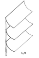
- the suction opening is advantageously provided with a lamella-like protective cover which is permeable to air and nevertheless, due to the specific arrangement and design of the lamellae, impedes or practically prevents water from entering.
- Water droplets attached to the slats are separated by tear-off bends and tear-off edges, possibly with the participation of the wind, on the inlet side of the air intake device. Detached drops are not entrained inside due to the low entry speed of the air.
- the overall arrangement is such that roof structures and body structures on vehicles are readily possible. Due to the snorkel and silencer design as one unit, there is a simple construction with few parts, which is accompanied by a weight saving compared to the known air intake devices. Due to the intended position of the intake opening, the cab surface is not vibrationally excited.
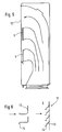
- an air intake device with noise damping device for sucking in combustion air for an internal combustion engine of a commercial vehicle is provided, and here the intake snorkel (1) of the air intake device is located in a vertical arrangement behind the driver's cab (2) of the commercial vehicle either on a vehicle outside according to FIG. 1 or in mirror image on both sides of the vehicle according to FIG. 2 if a double filter system is provided.
- the intake snorkel (1) is itself designed as a so-called reflection damper, which is also referred to as an interference damper.
- the interior of the intake snorkel (1) is subdivided into individual air guide sections (4, 5, 6) which run in parallel in the direction of flow (v) and which are defined by interchangeable air baffles (7) which in particular have the same or different lengths. This results in differently long, defined air flow paths during operation, which can therefore be matched to one another to the critical frequencies in operation in order to minimize the noise level for a particular engine design.
- the input sides of individual air duct sections can be provided with a cover (9) according to FIG. 5 in order, for example, to be able to carry out a further frequency tuning ⁇ / 2 or ⁇ / 4.
- a cover (9) according to FIG. 5 in order, for example, to be able to carry out a further frequency tuning ⁇ / 2 or ⁇ / 4.
- an additional damping volume (10) which is connected to the uppermost air duct section (4) exclusively via a passage opening (15).
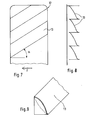
- the overall arrangement of the slats is in particular such that the lower edges of the slats (13) run obliquely upwards from the front to the rear of the vehicle, in particular an oblique angle ⁇ of at most 32 ° is provided (see FIG. 7).
- the droplets adhering to the lower edges are carried upwards on the slope by the driving wind, which is accompanied by accelerated tearing of the droplets.
- Falling drops are not entrained into the interior of the intake snorkel (1) due to the low air inlet speed due to the large cross section of the intake opening (3). Since the air inlet speed is low, suction noise is inherently very low and few dust particles are entrained. Internal additional water separation structures such as cyclones or the like are not necessary.
Landscapes
- Engineering & Computer Science (AREA)
- Chemical & Material Sciences (AREA)
- Combustion & Propulsion (AREA)
- Mechanical Engineering (AREA)
- General Engineering & Computer Science (AREA)
- Transportation (AREA)
- Cooling, Air Intake And Gas Exhaust, And Fuel Tank Arrangements In Propulsion Units (AREA)
Claims (14)
- Dispositif d'aspiration d'air d'un moteur à combustion interne d'un véhicule, ledit dispositif d'aspiration d'air comprenant un dispositif d'insonorisation et un schnorchel d'aspiration ayant la forme d'un amortisseur à réflexions comprenant un unique orifice d'aspiration, caractérisé en ce que le schnorchel d'aspiration (1) est subdivisé en sections individuelles de guidage d'air (4, 5, 6) qui se rétrécissent et sont parallèles dans le sens de la circulation (v) et qui ont des longueurs différentes.
- Dispositif d'aspiration d'air selon la revendication 1, caractérisé en ce que les sections individuelles de guidage d'air (4, 5, 6) sont courbes.
- Dispositif d'aspiration d'air selon la revendication 1 ou 2, caractérisé en ce que le schnorchel d'aspiration (1) comprend une enveloppe (8) formée d'un caisson haut et plat et il comporte des déflecteurs intérieurs et échangeables d'air (7) ayant la même longueur et/ou des longueurs différentes.
- Dispositif d'aspiration d'air selon l'une ou plusieurs des revendications 1 à 3, caractérisé en ce que les sections individuelles de guidage d'air sont munies à l'entrée d'un élément de couverture (9) (figure 5).
- Dispositif d'aspiration d'air selon la revendication 4, caractérisé en ce que les éléments de couverture (9) sont amovibles.
- Dispositif d'aspiration d'air selon l'une ou plusieurs des revendications 1 à 5, caractérisé en ce que le schnorchel d'aspiration (1) est disposé directement derrière l'habitacle (2) d'un véhicule utilitaire sur un côté et/ou sur les deux côtés du véhicule de manière symétriquement inverse dans le cas d'une installation double de filtrage.
- Dispositif d'aspiration d'air selon l'une ou plusieurs des revendications 1 à 6, caractérisé en ce qu'un volume supplémentaire d'amortissement (10) est réalisé au-dessus de la zone de la section supérieure de guidage d'air (4).
- Dispositif d'aspiration d'air selon l'une ou plusieurs des revendications 1 à 7, caractérisé en ce qu'un récipient latéral à eau (11) est réalisé sous la section inférieure de guidage d'air (6) dans la région située sous l'orifice d'aspiration (3).
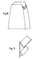
- Dispositif d'aspiration d'air selon l'une ou plusieurs des revendications 1 à 8, caractérisé en ce que l'orifice d'aspiration (2) est équipé d'un élément de couverture de protection (12) de type à lamelles qui laisse passer l'air et qui refoule l'eau.
- Dispositif d'aspiration d'air selon la revendication 9, caractérisé en ce que les lamelles individuelles parallèles et identiques (13) de l'élément de couverture de protection (12) sont orientées obliquement vers le bas et vers le côté extérieur du véhicule (figures 6 à 12).
- Dispositif d'aspiration d'air selon la revendication 10, caractérisé en ce que le bord inférieur des lamelles (13) comporte un coude (14) de détachement de l'eau (figure 6).
- Dispositif d'aspiration d'air selon la revendication 10 ou 11, caractérisé en ce que le bord inférieur des lamelles (13) est orienté obliquement vers le haut du côté antérieur vers le côté arrière du véhicule (7).
- Dispositif d'aspiration d'air selon la revendication 12, caractérisé en ce que l'obliquité du bord inférieur inscrit un angle a qui est au maximum de 32° sur l'horizontale.
- Dispositif d'aspiration d'air selon l'une ou plusieurs des revendications 3 à 13, caractérisé en ce que l'orifice étroit d'aspiration (3) se prolonge pratiquement sur la totalité de la hauteur de l'enveloppe (8) formée d'un caisson haut.
Applications Claiming Priority (2)
| Application Number | Priority Date | Filing Date | Title |
|---|---|---|---|
| DE3942595A DE3942595A1 (de) | 1989-12-22 | 1989-12-22 | Luftansaugvorrichtung fuer eine brennkraftmaschine |
| DE3942595 | 1989-12-22 |
Publications (2)
| Publication Number | Publication Date |
|---|---|
| EP0433923A1 EP0433923A1 (fr) | 1991-06-26 |
| EP0433923B1 true EP0433923B1 (fr) | 1993-09-15 |
Family
ID=6396219
Family Applications (1)
| Application Number | Title | Priority Date | Filing Date |
|---|---|---|---|
| EP90124281A Expired - Lifetime EP0433923B1 (fr) | 1989-12-22 | 1990-12-14 | Dispositif d'admission d'air pour un moteur à combustion interne |
Country Status (2)
| Country | Link |
|---|---|
| EP (1) | EP0433923B1 (fr) |
| DE (2) | DE3942595A1 (fr) |
Families Citing this family (19)
| Publication number | Priority date | Publication date | Assignee | Title |
|---|---|---|---|---|
| DE4205425A1 (de) * | 1991-11-02 | 1993-05-06 | Iveco Magirus Ag, 7900 Ulm, De | Luftansaugvorrichtung fuer eine brennkraftmaschine |
| DE19525086C1 (de) * | 1995-07-10 | 1996-10-10 | Daimler Benz Ag | Ansaugluftleitung für einen Verbrennungsmotor |
| DE19835104A1 (de) * | 1998-08-04 | 2000-02-10 | Man Nutzfahrzeuge Ag | Luftansauganlage für einen Dieselmotor in einem Lastkraftwagen |
| DE19835105A1 (de) | 1998-08-04 | 2000-02-10 | Man Nutzfahrzeuge Ag | Rohluftansaugkasten für einen Dieselmotor in einem Lastkraftwagen |
| ITMI20010791A1 (it) * | 2001-04-12 | 2002-10-12 | Cornaglia G Off Met Spa | Dispositivo di presa d'aria per un impianto di aspirazione in particolare di un veicolo industriale |
| BRPI0401703A (pt) * | 2004-05-06 | 2004-10-19 | Sogefi Filtration Do Brasil Lt | Dispositivo convergedor de fluxo de ar |
| JP5325764B2 (ja) * | 2009-12-25 | 2013-10-23 | 日野自動車株式会社 | 吸気ダクト及びその製造方法 |
| BR112012018640B1 (pt) * | 2010-01-29 | 2020-12-15 | Donaldson Company, Inc. | Montagens de separador de água de fluxo de ar de entrada e método de separar água de um fluxo de ar de entrada |
| DE102011101765B4 (de) * | 2011-05-17 | 2015-10-01 | Mann + Hummel Gmbh | Vorrichtung zur Abscheidung von Wasser aus der einer Brennkraftmaschine zuzuführenden Verbrennungsluft |
| DE102012015043B3 (de) * | 2012-07-31 | 2013-11-28 | Mann + Hummel Gmbh | Luftansaugvorrichtung einer Brennkraftmaschine und Leitungsmodul einer solchen |
| DE102013012629A1 (de) * | 2013-07-29 | 2015-01-29 | GM GLOBAL TECHNOLOGY OPERATION LLC (n. d. Ges. d. Staates Delaware) | Flüssigkeitsabscheider,Fluidführungseinrichtung und Kraftfahrzeug |
| GB2520066B (en) * | 2013-11-08 | 2019-12-04 | Leyland Trucks Ltd | Air intake assembly and duct therefor |
| DE102015007454A1 (de) * | 2015-06-05 | 2016-12-08 | GM Global Technology Operations LLC (n. d. Ges. d. Staates Delaware) | Lufteinlass für eine Heizungs-, Belüftuns,- oder Klimaanlage eines Kraftfahrzeugs |
| JP6556605B2 (ja) * | 2015-11-19 | 2019-08-07 | 日野自動車株式会社 | 吸気ダクト |
| US10801448B2 (en) | 2018-01-15 | 2020-10-13 | Ford Global Technologies, Llc | Integral intake manifold |
| US10815945B2 (en) * | 2018-01-15 | 2020-10-27 | Ford Global Technologies, Llc | Integral intake manifold |
| USD967199S1 (en) | 2019-10-16 | 2022-10-18 | Deere & Company | Air intake tower |
| US11181081B2 (en) * | 2019-10-16 | 2021-11-23 | Deere & Company | Air intake for work vehicle |
| USD966343S1 (en) | 2019-10-16 | 2022-10-11 | Deere & Company | Air intake tower |
Citations (1)
| Publication number | Priority date | Publication date | Assignee | Title |
|---|---|---|---|---|
| GB2055719A (en) * | 1979-08-07 | 1981-03-11 | Leyland Vehicles | Air intake for vehicle engine |
Family Cites Families (11)
| Publication number | Priority date | Publication date | Assignee | Title |
|---|---|---|---|---|
| DE757592C (de) * | 1940-05-09 | 1952-08-04 | Kloeckner Humboldt Deutz Ag | Anordnung fuer Luftfilter von Brennkraftmaschinen auf Fahrzeugen |
| GB722995A (en) * | 1951-03-06 | 1955-02-02 | Reginald Frank Fone | Improvements in or relating to road vehicles driven by internal combustion engines |
| FR1113611A (fr) * | 1953-11-21 | 1956-04-03 | Mode de montage des filtres à air, notamment à bain d'huile, utilisable sur les camions automobiles | |
| FR1123855A (fr) * | 1955-03-22 | 1956-10-01 | Tecalemit | Correcteur de carburation et silencieux d'admission |
| FR1355652A (fr) * | 1963-02-04 | 1964-03-20 | Polycarbure | Silencieux pour écoulement pulsatoire des fluides |
| FR1533136A (fr) * | 1967-08-03 | 1968-07-12 | Chiyoda Chem Eng Construct Co | Silencieux d'aspiration ou d'échappement pour fluides sous pression |
| DE1576592A1 (de) * | 1967-09-14 | 1970-06-18 | Augsburg Nuernberg Ag Zweignie | Vorrichtung zum Daempfen der Luftansauggeraeusche im Frontlenkerfahrerhaus eines Lastkraftwagens |
| DE7728139U1 (de) * | 1977-09-10 | 1978-06-01 | Filterwerk Mann & Hummel Gmbh, 7140 Ludwigsburg | Schutzhaube fuer die ansaugoeffnung eines ansaugluftfilters von brennkraftmaschinen, kompressoren oder sonstigen luftansaugenden maschinen |
| US4366878A (en) * | 1980-12-17 | 1983-01-04 | Paccar Inc. | Moisture-removing low-restriction air intake system |
| SE439751B (sv) * | 1984-09-07 | 1985-07-01 | Saab Scania Ab | Luftinloppskanal vid ett med en forarhytt forsett lastfordon |
| DE3836166A1 (de) * | 1988-10-24 | 1990-04-26 | Iveco Magirus | Luftansaugvorrichtung fuer eine brennkraftmaschine |
-
1989
- 1989-12-22 DE DE3942595A patent/DE3942595A1/de not_active Withdrawn
-
1990
- 1990-12-14 DE DE90124281T patent/DE59002739D1/de not_active Expired - Lifetime
- 1990-12-14 EP EP90124281A patent/EP0433923B1/fr not_active Expired - Lifetime
Patent Citations (1)
| Publication number | Priority date | Publication date | Assignee | Title |
|---|---|---|---|---|
| GB2055719A (en) * | 1979-08-07 | 1981-03-11 | Leyland Vehicles | Air intake for vehicle engine |
Also Published As
| Publication number | Publication date |
|---|---|
| DE3942595A1 (de) | 1991-06-27 |
| DE59002739D1 (de) | 1993-10-21 |
| EP0433923A1 (fr) | 1991-06-26 |
Similar Documents
| Publication | Publication Date | Title |
|---|---|---|
| EP0433923B1 (fr) | Dispositif d'admission d'air pour un moteur à combustion interne | |
| EP0541016B1 (fr) | Dispositif d'aspiration d'air pour un moteur à combustion interne | |
| DE60204753T2 (de) | Wasserabstossender kotflügel für kraftfahrzeuge und dergleichen | |
| DE3842248C2 (de) | Kombinierte Luftfilter- und Geräuschdämpfungsanordnung | |
| DE3840214A1 (de) | Lufteinlassgehaeuse fuer ein kraftfahrzeug | |
| EP1759112B1 (fr) | Filtre aspirateur pour moteur a combustion interne de vehicule | |
| DE10157897B4 (de) | Versorgungsvorrichtung für Verbrennungsluft einer Brennkraftmaschine eines Fahrzeugs | |
| DE2641444C2 (de) | Aggregateraum für Kraftwagen | |
| DE4033027A1 (de) | Vorrichtung zur geraeusch- und schwingungsminderung an tangential ueberstroemten oeffnungen von kraftfahrzeugen, insbesondere an schiebedachoeffnungen | |
| DE10012972C1 (de) | Belüftungsvorrichtung für Fahrzeuge | |
| DE4208999A1 (de) | Aerodynamisches, verstellbares unterbodenfrontende fuer kraftfahrzeuge | |
| DE10047731B4 (de) | Seitenwand für einen Personenkraftwagen | |
| DE4224051A1 (de) | Vorrichtung zur Frischluftzufuhr zum Fahrgastraum eines Fahrzeugs | |
| DE19822713A1 (de) | Windkanal | |
| DE10209132B4 (de) | Ansaugvorrichtung für Kaltluft | |
| EP1045769B1 (fr) | Entree d'air pour l'installation de chauffage ou de climatisation d'un vehicule automobile | |
| EP0365892B1 (fr) | Dispositif d'aspiration d'air pour un moteur à combustion interne | |
| DE4435292C2 (de) | Klimagerät | |
| DE102008061538A1 (de) | Kanalanordnung zum Führen von Prozessluft zu einer Verbrennungskraftmaschine | |
| EP0266767A2 (fr) | Agencement permettant l'introduction d'air extérieur pour la ventilation et/ou la climatisation d'une voiture automobile | |
| DE4401022C1 (de) | Belüftungsvorrichtung für Fahrzeuginnenräume | |
| DE102006044952A1 (de) | Vorrichtung zur Luftkühlung einer Radbremse an einem Kraftfahrzeug | |
| DE4026926A1 (de) | Innenraumluftfilter | |
| EP0978646A2 (fr) | Boítier d'admission d'air atmosphérique pour moteur diesel dans un camion | |
| DE102021122946B4 (de) | Kraftfahrzeug |
Legal Events
| Date | Code | Title | Description |
|---|---|---|---|
| PUAI | Public reference made under article 153(3) epc to a published international application that has entered the european phase |
Free format text: ORIGINAL CODE: 0009012 |
|
| AK | Designated contracting states |
Kind code of ref document: A1 Designated state(s): DE FR GB IT NL SE |
|
| 17P | Request for examination filed |
Effective date: 19910719 |
|
| 17Q | First examination report despatched |
Effective date: 19920403 |
|
| GRAA | (expected) grant |
Free format text: ORIGINAL CODE: 0009210 |
|
| AK | Designated contracting states |
Kind code of ref document: B1 Designated state(s): DE FR GB IT NL SE |
|
| ITF | It: translation for a ep patent filed | ||
| REF | Corresponds to: |
Ref document number: 59002739 Country of ref document: DE Date of ref document: 19931021 |
|
| GBT | Gb: translation of ep patent filed (gb section 77(6)(a)/1977) |
Effective date: 19931005 |
|
| ET | Fr: translation filed | ||
| PLBE | No opposition filed within time limit |
Free format text: ORIGINAL CODE: 0009261 |
|
| STAA | Information on the status of an ep patent application or granted ep patent |
Free format text: STATUS: NO OPPOSITION FILED WITHIN TIME LIMIT |
|
| 26N | No opposition filed | ||
| EAL | Se: european patent in force in sweden |
Ref document number: 90124281.8 |
|
| REG | Reference to a national code |
Ref country code: GB Ref legal event code: IF02 |
|
| PG25 | Lapsed in a contracting state [announced via postgrant information from national office to epo] |
Ref country code: IT Free format text: LAPSE BECAUSE OF NON-PAYMENT OF DUE FEES;WARNING: LAPSES OF ITALIAN PATENTS WITH EFFECTIVE DATE BEFORE 2007 MAY HAVE OCCURRED AT ANY TIME BEFORE 2007. THE CORRECT EFFECTIVE DATE MAY BE DIFFERENT FROM THE ONE RECORDED. Effective date: 20051214 |
|
| PGFP | Annual fee paid to national office [announced via postgrant information from national office to epo] |
Ref country code: SE Payment date: 20091120 Year of fee payment: 20 |
|
| PGFP | Annual fee paid to national office [announced via postgrant information from national office to epo] |
Ref country code: NL Payment date: 20091124 Year of fee payment: 20 |
|
| PGFP | Annual fee paid to national office [announced via postgrant information from national office to epo] |
Ref country code: GB Payment date: 20091125 Year of fee payment: 20 Ref country code: FR Payment date: 20091201 Year of fee payment: 20 |
|
| PGFP | Annual fee paid to national office [announced via postgrant information from national office to epo] |
Ref country code: DE Payment date: 20091120 Year of fee payment: 20 |
|
| REG | Reference to a national code |
Ref country code: NL Ref legal event code: V4 Effective date: 20101214 |
|
| REG | Reference to a national code |
Ref country code: GB Ref legal event code: PE20 Expiry date: 20101213 |
|
| EUG | Se: european patent has lapsed | ||
| PG25 | Lapsed in a contracting state [announced via postgrant information from national office to epo] |
Ref country code: GB Free format text: LAPSE BECAUSE OF EXPIRATION OF PROTECTION Effective date: 20101213 Ref country code: NL Free format text: LAPSE BECAUSE OF EXPIRATION OF PROTECTION Effective date: 20101214 |
|
| PGFP | Annual fee paid to national office [announced via postgrant information from national office to epo] |
Ref country code: IT Payment date: 20091203 Year of fee payment: 20 |
|
| PGRI | Patent reinstated in contracting state [announced from national office to epo] |
Ref country code: IT Effective date: 20110616 |
|
| PG25 | Lapsed in a contracting state [announced via postgrant information from national office to epo] |
Ref country code: DE Free format text: LAPSE BECAUSE OF EXPIRATION OF PROTECTION Effective date: 20101214 |