EP0433936A2 - Ventil- und Membranvorrichtung - Google Patents
Ventil- und MembranvorrichtungInfo
- Publication number
- EP0433936A2 EP0433936A2 EP90124392A EP90124392A EP0433936A2 EP 0433936 A2 EP0433936 A2 EP 0433936A2 EP 90124392 A EP90124392 A EP 90124392A EP 90124392 A EP90124392 A EP 90124392A EP 0433936 A2 EP0433936 A2 EP 0433936A2
- Authority
- EP
- European Patent Office
- Prior art keywords
- membrane
- passageway
- valve
- housing
- cavity
- Prior art date
- Legal status (The legal status is an assumption and is not a legal conclusion. Google has not performed a legal analysis and makes no representation as to the accuracy of the status listed.)
- Granted
Links
Images
Classifications
-
- G—PHYSICS
- G01—MEASURING; TESTING
- G01N—INVESTIGATING OR ANALYSING MATERIALS BY DETERMINING THEIR CHEMICAL OR PHYSICAL PROPERTIES
- G01N35/00—Automatic analysis not limited to methods or materials provided for in any single one of groups G01N1/00 - G01N33/00; Handling materials therefor
- G01N35/10—Devices for transferring samples or any liquids to, in, or from, the analysis apparatus, e.g. suction devices, injection devices
- G01N35/1095—Devices for transferring samples or any liquids to, in, or from, the analysis apparatus, e.g. suction devices, injection devices for supplying the samples to flow-through analysers
- G01N35/1097—Devices for transferring samples or any liquids to, in, or from, the analysis apparatus, e.g. suction devices, injection devices for supplying the samples to flow-through analysers characterised by the valves
-
- H—ELECTRICITY
- H01—ELECTRIC ELEMENTS
- H01J—ELECTRIC DISCHARGE TUBES OR DISCHARGE LAMPS
- H01J37/00—Discharge tubes with provision for introducing objects or material to be exposed to the discharge, e.g. for the purpose of examination or processing thereof
- H01J37/02—Details
- H01J37/20—Means for supporting or positioning the object or the material; Means for adjusting diaphragms or lenses associated with the support
-
- H—ELECTRICITY
- H01—ELECTRIC ELEMENTS
- H01J—ELECTRIC DISCHARGE TUBES OR DISCHARGE LAMPS
- H01J49/00—Particle spectrometers or separator tubes
- H01J49/02—Details
- H01J49/04—Arrangements for introducing or extracting samples to be analysed, e.g. vacuum locks; Arrangements for external adjustment of electron- or ion-optical components
- H01J49/0431—Arrangements for introducing or extracting samples to be analysed, e.g. vacuum locks; Arrangements for external adjustment of electron- or ion-optical components for liquid samples
- H01J49/0436—Arrangements for introducing or extracting samples to be analysed, e.g. vacuum locks; Arrangements for external adjustment of electron- or ion-optical components for liquid samples using a membrane permeable to liquids
Definitions
- Membrane cells are used in chemical analysis to partition a sample contained on one side of a membrane from a compartment positioned on the other side of the membrane.
- the sample contains a component of interest that permeates through, i.e., across, the membrane into the compartment.
- the permeated component of interest in this compartment can then be analyzed. If the sample contains another component that does not permeate through the membrane which otherwise would interfere with the analysis of the component of interest, then the use of a membrane cell in the analysis of the component of interest is beneficial.
- Membrane cells can use sheet type membranes or tubular type membranes.
- a cell using a sheet type membrane can be made by clamping the membrane between two housing portions, each portion having a cavity exposed to the membrane. The cavities are in a juxtaposed position such that they face the membrane.
- a sample containing a component of interest is placed in one of the cavities. The component of interest permeates through the membrane into the other cavity. The contents of the other cavity are then analyzed for the permeated component of interest.
- a cell using a tubular type membrane can be made by sealing the outer end portions of a tubular membrane to the inner end portions of a metal tube leaving an annular space between the central portion of the inside of the metal tube and the central portion of the outside of the tubular membrane. A sample containing a component of interest can be placed in the annular space.
- the component of interest permeates through the membrane into the bore of the membrane.
- the contents of the bore of the membrane are then analyzed for the permeated component of interest.
- the sample can be placed in the bore of the tubular membrane and the contents of the annular space can be analyzed.
- the membrane of a membrane cell is used to partition a sample from the vacuum inlet of a mass spectrometer.
- a component of interest of the sample placed on one side of the membrane permeates across the membrane, passes into the partial vacuum on the other side of the membrane as a gas or vapor and is flowed into the mass spectrometer for analysis.
- a valve is placed in the vacuum line between the membrane cell and the mass spectrometer so that passage of the component of interest into the mass spectrometer can be stopped if desired.
- several membrane cells are connected to a mass spectrometer through such valves so that each can be respectively analyzed in turn. It would be an advance in this art if the valve and the membrane cell could be combined into one device to reduce the number of apparatus components needed.
- the present invention resides in a valve and membrane device, comprising: (a) a semipermeable membrane having a first side and a second side; (b) a valve body defining a cavity therein, said cavity being partitioned by the membrane into a first cavity portion exposed to said first side of said membrane and a second cavity portion exposed to said second side of said membrane, said valve body having first, second and third passageways extending thereinto, said first and second passageways opening into said first cavity portion, said third passageway opening into said second cavity portion for flow of a fluid through said first passageway into said first cavity portion and then through said second passageway and for permeation of a fluid component across said membrane into said second cavity portion for flow out of said valve body through said third passageway; and (c) means positioned within said cavity for controlling the flow of said fluid component through said third passageway.
- the third passageway When used in a mass spectrometry system, the third passageway is connected to the vacuum inlet of the mass spectrometer. A sample is flowed into the first passageway, into the first cavity portion, where it comes into contact with the membrane, and is then passed out the second passageway. When the third passageway is open, a component of the sample that has permeated across the membrane into the second cavity portion flows as a gas or vapor into the vacuum inlet of the mass spectrometer.
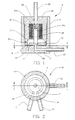
- Fig. 1 is a cross-sectional side view of a device according to the present invention, the device incorporating a sheet type membrane;
- Fig. 2 is a cross-sectional top view of the device shown in Fig. 1 when taken along section line 2-2 of Fig. 1;
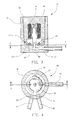
- Fig. 3 is a cross-sectional side view of a device according to the present invention, the device incorporating a tubular membrane;
- Fig. 4 is a cross-sectional top view of the device shown in Fig. 3 when taken along section line 4-4 of Fig. 3;
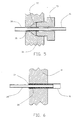
- Fig. 5 is a cross-sectional enlarged side view of one means of sealing a tubular membrane to the body of the device;
- Fig. 6 is a cross-sectional enlarged side view of another means of sealing a tubular membrane to the body of the device.
- a valve and membrane device l0 comprising a housing 11 and a plug 12.
- the housing 11 and the plug 12 are provided with mating threads as shown.
- the housing 11 and the plug 12 form the body of the device 10 and define a cavity 13 therein.
- the housing 11 and the plug 12 are preferably made from stainless steel but can be made of almost any other suitable material such as another metal, a ceramic or a polymer.
- the housing 11 has a circular channel 14 machined in a bottom portion. However, the geometry of the channel is not critical and it could be in a spiral shape, a zigzag shape, a rectangular or other shape.
- the housing 11 has a first passageway 15 from the exterior of the housing 11 to one end of the channel 14 and a second passageway 16 from the exterior of the housing 11 to the other end of the channel 14.
- the housing 11 further has a third passageway 17 extending from the exterior of the housing 11 to the chamber 13.
- a washer 17a and a sheet membrane 18 are sandwiched between the plug 12 and the housing 11.
- a series of holes 19 are drilled in the washer 17a opposite the channel 14.
- An O-ring 20 seals the washer 17a, the housing 11 and the plug 12. One side of the membrane 18 is thus exposed to the chamber 13 via the holes 19 in the washer 17a while the other side of the membrane 18 is exposed to the channel 14.
- a section of tubing 21 is joined with the housing 11 to extend the first passageway 15 and the tubing 21 is a part of the valve body.
- a section of tubing 22 is also joined with the housing 11 to extend the second passageway 16 and the tubing 22 is a part of the valve body.
- a section of tubing 23 is also joined with the housing 11 to extend the third passageway 17 and the tubing 23 is a part of the valve body.
- a coil spring 24 is positioned in a central channel of the plug 12 to urge a solenoid plunger 25 having a resilient seal 26 on an end thereof against the portion of the housing 11 where the third passageway enters the chamber 13 closing the third passageway 17.
- a terminal portion of the plunger 25 and the seal 26 extend into the chamber 13.
- the plug 12 has a fourth passageway 28 from the exterior of the plug 12 to the chamber 13.
- a section of tubing 29 is joined with the plug 12 to extend the passageway 28.
- a resilient seal 26a is positioned on the top of the plunger 25.
- the device 10 is shown as a solenoid valve it should be understood that this is not critical and that most any valve means can be used to controllably close or control the flow through the fourth and/or third passageways including a manually actuated valve, a pneumatically actuated valve or even a piezoelectrically operated valve.
- the tubing 29 is connected to a vacuum pump and a sample containing a component that permeates across the membrane 18 is flowed into the tubing 21, through the channel 14 and out the tubing 22 while the vacuum inlet of the mass spectrometer is connected to the tubing 23.
- the solenoid coil 27 When the solenoid coil 27 is energized, the component of interest that permeates across the membrane 18 into the chamber 13 can flow through the passageway 17 into the mass spectrometer.
- Connecting a vacuum pump to the tubing 29 is preferred in this application to prevent a pressure surge into the mass spectrometer when the solenoid coil 27 is energized.
- Several valves of the present invention can be connected to the vacuum inlet of a mass spectrometer so that each can be analyzed as desired.
- the heat generated by the solenoid coil 27 can be a problem because permeation across the membrane 18 can vary with temperature.
- a solution to this problem that has been found to be effective is to cool the solenoid coil 27 with coolant pumped through a tube coil positioned below the solenoid coil 27.
- a pneumatically actuated valve can be used.
- a device 30 similar in many respects to the device 10 shown in Fig. 1 and 2, incorporating a housing 31 and a plug 32.
- the housing 31 and the plug 32 are provided with mating threads as shown.
- the housing 31 and the plug 32 form the body of the device 30 and define a cavity 33 therein.
- the housing 31 has a first passageway 35 from the exterior of the housing 31 to the cavity 33.
- the housing 31 also has a second passageway 36 from the exterior of the housing 31 to the chamber 33.
- the housing 31 further has a third passageway 37 from the exterior of the housing 31 to the chamber 33.
- An O-ring 40 seals the housing 31 to the plug 32.
- a tubular membrane 38 is positioned with one end portion in the first passageway 35 and the other end portion in the second passageway 36.
- the outer end portions of the membrane 38 need to be continuously sealed to the inside surfaces of the passageways 35 and 36 since only membrane permeation communication between the bore of the membrane 38 and the chamber 33 is desirable. Two alternatives for such sealing will be discussed below with reference to Fig. 5 and 6.
- the central portion of the tubular membrane 38 is secured to the bottom surface of chamber 33 with a room temperature vulcanizing silicone rubber sealant 39.
- a section of tubing 41 is joined with the housing 31 to extend the first passageway 35 and the tubing 41 is a part of the valve body.
- a section of tubing 42 is also joined with the housing 31 to extend the second passageway 36 and the tubing 42 is a part of the valve body.
- a section of tubing 43 is also joined with the housing 31 to extend the third passageway 37 and the tubing 43 is a part of the valve body.
- a coil spring 44 is positioned in a central channel of the plug 32 to urge a solenoid plunger having a resilient seal 46 on an end thereof against the portion of the housing 31 where the third passageway enters the chamber 33 closing the third passageway 37.
- the plunger and its seal 46 are thus positioned within the cavity 33.
- a solenoid coil 47 when energized, pulls the plunger 45 and the seal 46 upward opening the third passageway 37.
- the device 30 is shown as a solenoid valve it should be understood that this is not at all critical and that most any valve can be used to control flow in the third passageway including a manually actuated valve, a pneumatically actuated valve or even a piezoelectrically operated valve.
- a room temperature vulcanizing silicone rubber sealant 34 is used to seal the tubular membrane 38 in the passageway 35 and in the tubing 41.
- the tube 41 is dimensioned to fit inside the tubular membrane 38 to form a portion where the membrane 38 overlaps the end portion of the tube 41.
- the portion where the membrane 38 overlaps the tube 41 is placed within a ferrule 50.
- a nut 51 compresses the ferrule 50 to seal the overlapping portion of the tubular membrane 38 to the tubing 41.
- the embodiment of Fig. 5 allows easier replacement of the membrane 38 in the valve 30.
- the apparatus of the present invention can be used in many applications in addition to those mentioned above.
- it could be used on the inlet of a gas chromatography system to introduce a permeated component of interest into a gas chromatography column or into the injection valve of a gas chromatography system.
- it could be incorporated into a probe inserted directly into the vacuum chamber of a mass spectrometer.
- the membrane of the present invention must be a selectively permeable membrane and not an impermeable membrane such as a sheet metal diaphragm of the type that has long been used in valves such as pressure regulation valves.
- the membrane of the present invention can be nonporous or porous as long as it is selectively permeable to the component of interest, i.e., that the rate of permeation of the component of interest across the membrane be different than the rate of permeation across the membrane of another component.
- Sheet and tubular membranes of nonporous silicone rubber are preferred examples.
- suitable membrane materials include porous polyethylene membranes (such as Celgard brand sheet or tubular membranes from the Celanese Corporation of the United States of America), membranes made from polytetrafluoroethylene, polycarbonate, other rubbers and ion exchange polymers (such as Nafion brand ion exchange membranes from DuPont of the United States of America).
- porous polyethylene membranes such as Celgard brand sheet or tubular membranes from the Celanese Corporation of the United States of America
- membranes made from polytetrafluoroethylene, polycarbonate, other rubbers and ion exchange polymers such as Nafion brand ion exchange membranes from DuPont of the United States of America.
- ion exchange polymers such as Nafion brand ion exchange membranes from DuPont of the United States of America.
- Many other examples of suitable membranes can be found commercially available or described in publications such as Membranes in Separations by professors Hwang
Landscapes
- Chemical & Material Sciences (AREA)
- Analytical Chemistry (AREA)
- Physics & Mathematics (AREA)
- Health & Medical Sciences (AREA)
- Life Sciences & Earth Sciences (AREA)
- Biochemistry (AREA)
- General Health & Medical Sciences (AREA)
- General Physics & Mathematics (AREA)
- Immunology (AREA)
- Pathology (AREA)
- Electron Tubes For Measurement (AREA)
- Sampling And Sample Adjustment (AREA)
- Separation Using Semi-Permeable Membranes (AREA)
- Other Investigation Or Analysis Of Materials By Electrical Means (AREA)
Applications Claiming Priority (2)
| Application Number | Priority Date | Filing Date | Title |
|---|---|---|---|
| US07/455,472 US5019139A (en) | 1989-12-22 | 1989-12-22 | Valve membrane combination |
| US455472 | 1989-12-22 |
Publications (3)
| Publication Number | Publication Date |
|---|---|
| EP0433936A2 true EP0433936A2 (de) | 1991-06-26 |
| EP0433936A3 EP0433936A3 (en) | 1991-09-25 |
| EP0433936B1 EP0433936B1 (de) | 1996-01-10 |
Family
ID=23808943
Family Applications (1)
| Application Number | Title | Priority Date | Filing Date |
|---|---|---|---|
| EP90124392A Expired - Lifetime EP0433936B1 (de) | 1989-12-22 | 1990-12-17 | Ventil- und Membranvorrichtung |
Country Status (6)
| Country | Link |
|---|---|
| US (1) | US5019139A (de) |
| EP (1) | EP0433936B1 (de) |
| JP (1) | JPH06205923A (de) |
| CA (1) | CA2032946A1 (de) |
| DE (1) | DE69024775T2 (de) |
| ES (1) | ES2081336T3 (de) |
Cited By (5)
| Publication number | Priority date | Publication date | Assignee | Title |
|---|---|---|---|---|
| DE9109797U1 (de) * | 1991-08-07 | 1991-09-26 | Wissenschaftliche Gerätebau Dr.-Ing. Herbert Knauer GmbH, 1000 Berlin | Gerät zur Durchführung von chemischen Prozessen an einer Probe eines chemischen Materials |
| WO1999020329A1 (en) * | 1997-10-20 | 1999-04-29 | Hans Degn | Dosing unit and a method of continuous introduction of liquid solution samples into a system |
| GB2348380A (en) * | 1999-03-29 | 2000-10-04 | Medeval Limited | Sampling apparatus with silicone rubber membrane |
| GB2411046A (en) * | 2004-02-12 | 2005-08-17 | Microsaic Systems Ltd | Mass spectrometer system |
| US20110198494A1 (en) * | 2008-10-07 | 2011-08-18 | The Science And Technology Facilities Council | Mass discriminator |
Families Citing this family (9)
| Publication number | Priority date | Publication date | Assignee | Title |
|---|---|---|---|---|
| US5233876A (en) * | 1991-04-04 | 1993-08-10 | The Dow Chemical Company | Apparatus and methods for on-line analysis of one or more process streams |
| US6017117A (en) * | 1995-10-31 | 2000-01-25 | Hewlett-Packard Company | Printhead with pump driven ink circulation |
| US5703359A (en) * | 1996-07-29 | 1997-12-30 | Leybold Inficon, Inc. | Composite membrane and support assembly |
| US5795355A (en) * | 1996-12-24 | 1998-08-18 | Applied Materials, Inc. | Integrated micro-environment container loader apparatus having a semipermeable barrier |
| US6121609A (en) * | 1998-10-16 | 2000-09-19 | Siemens Aktiengesellschaft | Pulsed mass spectrometer leak valve with controlled energy closure |
| KR102178191B1 (ko) | 2008-09-02 | 2020-11-13 | 머크 밀리포어 리미티드 | 크로마토그래피 막, 이를 포함하는 장치 및 이의 이용방법 |
| US9873088B2 (en) | 2011-05-17 | 2018-01-23 | Natrix Separations Inc. | Layered tubular membranes for chromatography, and methods of use thereof |
| US9150756B2 (en) | 2011-08-10 | 2015-10-06 | Hamilton Space Systems International, Inc. | Sampling device for substance detection instrument |
| CN113710434B (zh) * | 2019-02-01 | 2024-07-09 | 耐克塞拉机器人公司 | 电磁夹持装置 |
Family Cites Families (12)
| Publication number | Priority date | Publication date | Assignee | Title |
|---|---|---|---|---|
| US1174631A (en) * | 1914-09-17 | 1916-03-07 | Walter O Snelling | Apparatus for separating gases. |
| US2045379A (en) * | 1932-09-23 | 1936-06-23 | Catalyst Research Corp | Apparatus for diffusing gases |
| GB860752A (en) * | 1943-01-20 | 1961-02-08 | Atomic Energy Authority Uk | Improvements in or relating to the separation of gaseous and vaporous media |
| US3455092A (en) * | 1965-12-06 | 1969-07-15 | Varian Associates | Gas analyzer inlet system for gaseous state materials |
| US3494174A (en) * | 1968-01-30 | 1970-02-10 | Varian Associates | Gas chromatography apparatus |
| US3638401A (en) * | 1969-03-24 | 1972-02-01 | Varian Associates | Vacuum connector for connecting replaceable evacuated devices to an evacuated system |
| US3662520A (en) * | 1969-10-24 | 1972-05-16 | Us Navy | System for gas analysis and molecular gas separator |
| US3668837A (en) * | 1970-02-13 | 1972-06-13 | Pall Corp | Separator of the semipermeable membrane type |
| US3721065A (en) * | 1971-01-27 | 1973-03-20 | Int Paper Co | Barrier attachment for gas chromatograph |
| US4003725A (en) * | 1975-05-12 | 1977-01-18 | Trienco, Inc. | Apparatus for purifying hydrogen gas |
| CA1194338A (en) * | 1982-08-24 | 1985-10-01 | James Kesson | Method of and apparatus for monitoring concentration of gas in a liquid |
| US4808199A (en) * | 1987-03-31 | 1989-02-28 | W. R. Grace & Co.-Conn. | Apparatus and method for protecting gas separation membranes from damage due to a reversal of differential pressure |
-
1989
- 1989-12-22 US US07/455,472 patent/US5019139A/en not_active Expired - Lifetime
-
1990
- 1990-12-17 EP EP90124392A patent/EP0433936B1/de not_active Expired - Lifetime
- 1990-12-17 DE DE69024775T patent/DE69024775T2/de not_active Expired - Fee Related
- 1990-12-17 ES ES90124392T patent/ES2081336T3/es not_active Expired - Lifetime
- 1990-12-21 CA CA002032946A patent/CA2032946A1/en not_active Abandoned
- 1990-12-21 JP JP2418042A patent/JPH06205923A/ja active Pending
Cited By (10)
| Publication number | Priority date | Publication date | Assignee | Title |
|---|---|---|---|---|
| DE9109797U1 (de) * | 1991-08-07 | 1991-09-26 | Wissenschaftliche Gerätebau Dr.-Ing. Herbert Knauer GmbH, 1000 Berlin | Gerät zur Durchführung von chemischen Prozessen an einer Probe eines chemischen Materials |
| WO1999020329A1 (en) * | 1997-10-20 | 1999-04-29 | Hans Degn | Dosing unit and a method of continuous introduction of liquid solution samples into a system |
| US6558630B1 (en) | 1997-10-20 | 2003-05-06 | Hans Degn | Dosing unit and a method of continuous introduction of liquid solution samples into a system |
| GB2348380A (en) * | 1999-03-29 | 2000-10-04 | Medeval Limited | Sampling apparatus with silicone rubber membrane |
| GB2348380B (en) * | 1999-03-29 | 2003-04-23 | Medeval Ltd | Sampling apparatus and method of sampling using same |
| GB2411046A (en) * | 2004-02-12 | 2005-08-17 | Microsaic Systems Ltd | Mass spectrometer system |
| GB2411046B (en) * | 2004-02-12 | 2006-10-25 | Microsaic Systems Ltd | Mass spectrometer system |
| US7750292B2 (en) | 2004-02-12 | 2010-07-06 | Microsaic Systems Limited | Mass spectrometer system |
| US20110198494A1 (en) * | 2008-10-07 | 2011-08-18 | The Science And Technology Facilities Council | Mass discriminator |
| US8653453B2 (en) | 2008-10-07 | 2014-02-18 | The Science And Technology Facilities Council, Harwell Innovation Campus, Rutherford Appleton Laboratory | Mass discriminator |
Also Published As
| Publication number | Publication date |
|---|---|
| ES2081336T3 (es) | 1996-03-01 |
| EP0433936B1 (de) | 1996-01-10 |
| JPH06205923A (ja) | 1994-07-26 |
| DE69024775T2 (de) | 1996-08-14 |
| EP0433936A3 (en) | 1991-09-25 |
| US5019139A (en) | 1991-05-28 |
| CA2032946A1 (en) | 1991-06-23 |
| DE69024775D1 (de) | 1996-02-22 |
Similar Documents
| Publication | Publication Date | Title |
|---|---|---|
| EP0433936B1 (de) | Ventil- und Membranvorrichtung | |
| EP0469913B1 (de) | Ventil zur Regelung des Flüssigkeitsdurchflusses | |
| EP0528947B1 (de) | Ventilsystem mit abnehmbarem fluidtrennkörper | |
| US5487313A (en) | Fluid-lock fixed-volume injector | |
| US5660370A (en) | Valve with flexible sheet member and two port non-flexing backer member | |
| FI84854B (fi) | Kopplande mini-elventil. | |
| US11111911B2 (en) | Degassing apparatus | |
| JPH11137907A (ja) | 脱気装置 | |
| US5082788A (en) | Method of sequencing peptides and proteins using a valve block assembly | |
| US4515184A (en) | Modular directional valve | |
| JP2007511340A (ja) | 軸方向移送ラインガス抜き | |
| JPS6334354B2 (de) | ||
| US3787026A (en) | Chromatography valve | |
| US5197192A (en) | Method of making a fluid control valve | |
| US3638401A (en) | Vacuum connector for connecting replaceable evacuated devices to an evacuated system | |
| JPS631877A (ja) | マイクロエレクトロバルブ | |
| EP0830534B1 (de) | Mengenverhältnis-dosierventil | |
| US3917523A (en) | Electrochemical electrode structure | |
| US4112766A (en) | Fluid actuated valve | |
| US5364068A (en) | Valve block assembly | |
| US3430417A (en) | Gas sample enrichment device | |
| US20080290309A1 (en) | Pin Valve Assembly | |
| CN113153683B (zh) | 多级电渗微泵 | |
| US4002070A (en) | Sample injection system | |
| US6862916B2 (en) | Gas chromatograph sample valve |
Legal Events
| Date | Code | Title | Description |
|---|---|---|---|
| PUAI | Public reference made under article 153(3) epc to a published international application that has entered the european phase |
Free format text: ORIGINAL CODE: 0009012 |
|
| AK | Designated contracting states |
Kind code of ref document: A2 Designated state(s): DE ES FR GB NL |
|
| PUAL | Search report despatched |
Free format text: ORIGINAL CODE: 0009013 |
|
| RHK1 | Main classification (correction) |
Ipc: H01J 49/04 |
|
| AK | Designated contracting states |
Kind code of ref document: A3 Designated state(s): DE ES FR GB NL |
|
| 17P | Request for examination filed |
Effective date: 19920311 |
|
| 17Q | First examination report despatched |
Effective date: 19950203 |
|
| GRAA | (expected) grant |
Free format text: ORIGINAL CODE: 0009210 |
|
| AK | Designated contracting states |
Kind code of ref document: B1 Designated state(s): DE ES FR GB NL |
|
| REF | Corresponds to: |
Ref document number: 69024775 Country of ref document: DE Date of ref document: 19960222 |
|
| ET | Fr: translation filed | ||
| REG | Reference to a national code |
Ref country code: ES Ref legal event code: FG2A Ref document number: 2081336 Country of ref document: ES Kind code of ref document: T3 |
|
| PLBE | No opposition filed within time limit |
Free format text: ORIGINAL CODE: 0009261 |
|
| STAA | Information on the status of an ep patent application or granted ep patent |
Free format text: STATUS: NO OPPOSITION FILED WITHIN TIME LIMIT |
|
| 26N | No opposition filed | ||
| PGFP | Annual fee paid to national office [announced via postgrant information from national office to epo] |
Ref country code: FR Payment date: 19970825 Year of fee payment: 8 |
|
| PGFP | Annual fee paid to national office [announced via postgrant information from national office to epo] |
Ref country code: ES Payment date: 19971222 Year of fee payment: 8 |
|
| PGFP | Annual fee paid to national office [announced via postgrant information from national office to epo] |
Ref country code: NL Payment date: 19971231 Year of fee payment: 8 |
|
| PG25 | Lapsed in a contracting state [announced via postgrant information from national office to epo] |
Ref country code: ES Free format text: LAPSE BECAUSE OF EXPIRATION OF PROTECTION Effective date: 19981218 |
|
| PG25 | Lapsed in a contracting state [announced via postgrant information from national office to epo] |
Ref country code: NL Free format text: LAPSE BECAUSE OF NON-PAYMENT OF DUE FEES Effective date: 19990701 |
|
| PG25 | Lapsed in a contracting state [announced via postgrant information from national office to epo] |
Ref country code: FR Free format text: LAPSE BECAUSE OF NON-PAYMENT OF DUE FEES Effective date: 19990831 |
|
| NLV4 | Nl: lapsed or anulled due to non-payment of the annual fee |
Effective date: 19990701 |
|
| REG | Reference to a national code |
Ref country code: FR Ref legal event code: ST |
|
| REG | Reference to a national code |
Ref country code: ES Ref legal event code: FD2A Effective date: 20010301 |
|
| REG | Reference to a national code |
Ref country code: GB Ref legal event code: IF02 |
|
| PGFP | Annual fee paid to national office [announced via postgrant information from national office to epo] |
Ref country code: GB Payment date: 20040923 Year of fee payment: 15 |
|
| PGFP | Annual fee paid to national office [announced via postgrant information from national office to epo] |
Ref country code: DE Payment date: 20041019 Year of fee payment: 15 |
|
| PG25 | Lapsed in a contracting state [announced via postgrant information from national office to epo] |
Ref country code: GB Free format text: LAPSE BECAUSE OF NON-PAYMENT OF DUE FEES Effective date: 20051217 |
|
| PG25 | Lapsed in a contracting state [announced via postgrant information from national office to epo] |
Ref country code: DE Free format text: LAPSE BECAUSE OF NON-PAYMENT OF DUE FEES Effective date: 20060701 |
|
| GBPC | Gb: european patent ceased through non-payment of renewal fee |
Effective date: 20051217 |