EP0435218A1 - Verfahren und Vorrichtung zum Laden von Fahrzeugen - Google Patents
Verfahren und Vorrichtung zum Laden von Fahrzeugen Download PDFInfo
- Publication number
- EP0435218A1 EP0435218A1 EP90125235A EP90125235A EP0435218A1 EP 0435218 A1 EP0435218 A1 EP 0435218A1 EP 90125235 A EP90125235 A EP 90125235A EP 90125235 A EP90125235 A EP 90125235A EP 0435218 A1 EP0435218 A1 EP 0435218A1
- Authority
- EP
- European Patent Office
- Prior art keywords
- frame
- car
- frames
- container
- cars
- Prior art date
- Legal status (The legal status is an assumption and is not a legal conclusion. Google has not performed a legal analysis and makes no representation as to the accuracy of the status listed.)
- Granted
Links
Images







Classifications
-
- B—PERFORMING OPERATIONS; TRANSPORTING
- B65—CONVEYING; PACKING; STORING; HANDLING THIN OR FILAMENTARY MATERIAL
- B65D—CONTAINERS FOR STORAGE OR TRANSPORT OF ARTICLES OR MATERIALS, e.g. BAGS, BARRELS, BOTTLES, BOXES, CANS, CARTONS, CRATES, DRUMS, JARS, TANKS, HOPPERS, FORWARDING CONTAINERS; ACCESSORIES, CLOSURES, OR FITTINGS THEREFOR; PACKAGING ELEMENTS; PACKAGES
- B65D88/00—Large containers
- B65D88/54—Large containers characterised by means facilitating filling or emptying
- B65D88/542—Ramps forming part of the container
-
- B—PERFORMING OPERATIONS; TRANSPORTING
- B65—CONVEYING; PACKING; STORING; HANDLING THIN OR FILAMENTARY MATERIAL
- B65D—CONTAINERS FOR STORAGE OR TRANSPORT OF ARTICLES OR MATERIALS, e.g. BAGS, BARRELS, BOTTLES, BOXES, CANS, CARTONS, CRATES, DRUMS, JARS, TANKS, HOPPERS, FORWARDING CONTAINERS; ACCESSORIES, CLOSURES, OR FITTINGS THEREFOR; PACKAGING ELEMENTS; PACKAGES
- B65D88/00—Large containers
- B65D88/02—Large containers rigid
- B65D88/12—Large containers rigid specially adapted for transport
- B65D88/122—Large containers rigid specially adapted for transport with access from above
- B65D88/123—Large containers rigid specially adapted for transport with access from above open top
-
- B—PERFORMING OPERATIONS; TRANSPORTING
- B65—CONVEYING; PACKING; STORING; HANDLING THIN OR FILAMENTARY MATERIAL
- B65D—CONTAINERS FOR STORAGE OR TRANSPORT OF ARTICLES OR MATERIALS, e.g. BAGS, BARRELS, BOTTLES, BOXES, CANS, CARTONS, CRATES, DRUMS, JARS, TANKS, HOPPERS, FORWARDING CONTAINERS; ACCESSORIES, CLOSURES, OR FITTINGS THEREFOR; PACKAGING ELEMENTS; PACKAGES
- B65D2585/00—Containers, packaging elements or packages specially adapted for particular articles or materials
- B65D2585/68—Containers, packaging elements or packages specially adapted for particular articles or materials for machines, engines, or vehicles in assembled or dismantled form
- B65D2585/6802—Containers, packaging elements or packages specially adapted for particular articles or materials for machines, engines, or vehicles in assembled or dismantled form specific machines, engines or vehicles
- B65D2585/686—Containers, packaging elements or packages specially adapted for particular articles or materials for machines, engines, or vehicles in assembled or dismantled form specific machines, engines or vehicles vehicles
- B65D2585/6867—Containers, packaging elements or packages specially adapted for particular articles or materials for machines, engines, or vehicles in assembled or dismantled form specific machines, engines or vehicles vehicles automobiles
-
- B—PERFORMING OPERATIONS; TRANSPORTING
- B65—CONVEYING; PACKING; STORING; HANDLING THIN OR FILAMENTARY MATERIAL
- B65G—TRANSPORT OR STORAGE DEVICES, e.g. CONVEYORS FOR LOADING OR TIPPING, SHOP CONVEYOR SYSTEMS OR PNEUMATIC TUBE CONVEYORS
- B65G2201/00—Indexing codes relating to handling devices, e.g. conveyors, characterised by the type of product or load being conveyed or handled
- B65G2201/02—Articles
- B65G2201/0294—Vehicle bodies
Definitions
- the present invention relates to a car loading apparatus used for loading a plurality of automobiles in two tiers into a container for transportation.
- a container for loading automobiles was used exclusively for automobiles.
- Such a container is provided inside with car-loading apparatus comprising a plurality of sets of load-supporting columns and lifts.
- the loading apparatus since the lift of the car-loading apparatus requires driving means for driving itself to put automobiles in two tiers, the loading apparatus has a very complicated structure.
- One solution for the above-described various problems is to put a car in a loading apparatus comprising a box-shaped frame having suitable length, width and height for accommodating a car, to put another car on this loading apparatus and to carry it into a container.
- Two cars are mounted on the car loading apparatus according to this invention, one on the car-mounting frame of the base frame and the other on the car-mounting frame placed on the box frame.
- a first car is brought onto the lower deck with the rear rectangular frame of the box frame held open. Then after mounting the connecting frame and the car-mounting frame necessary for carrying a car on the upper deck, a second car is brought onto the upper deck.
- the cars are lashed to the box frame by the lashing devices.
- the lashing devices for the car on the upper deck are pulled with a greater force to lower the height of the car on the upper deck by compressing its suspension springs and wheel tyres so that it can pass through the entrance of the container without hitting its top frame.
- the entire apparatus After lashing the cars, the entire apparatus is pushed into the container by human hands.
- the car loading apparatus is sufficiently rigid and light in weight. Cars can be loaded in two tiers. This apparatus can be moved easily by human hands with two cars loaded. Its entire height when two cars are mounted can be lowered sufficiently so that the car on the upper deck can pass through the entrance of the container without hitting its top frame.
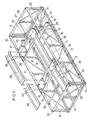
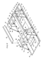
- FIG. 1 is a schematic view showing the entire structure of this embodiment.
- a box frame 10 comprises a longitudinally extending rectangular side frames 11, rectangular end frames 12 and a base frame 13 supporting the frames 11 and 12.
- These rectangular frames are trussed frames each comprising upper and lower parallel members with a plurality of vertical and oblique frames provided therebetween.
- the frame 13 is in the shape of a rectangle and is provided at four corners thereof with square columns 14.
- the base frame 13 is provided with two pairs of connecting frames 15 extending between the side frames 11, each pair being at locations corresponding to the front and rear wheels of a car when it is loaded in position. Further, right and left car mounting frames 16 are mounted on the base frame 13 to extend longitudinally across the connecting frames 15 and one base frame 13 from which a car is carried in. A stopper 17 is provided at the front end of each frame 16.
- the square columns 14 at the four corners of the base frame 13 are each provided with hinges 18 and 19.
- the side rectangular frames 11 and the end rectangular frames 12 are rotatably mounted on the base frame 13 by the hinges 18 and 19, respectively.
- When assembling the rectangular frames 11 and 12 into the box frame they are fixed together at their top abutting ends by use of bolts 20.
- Four rollers 21 are mounted on each of the longitudinal frames of the base frame 13 so that the entire loading apparatus can be moved with cars mountd thereon. (Fig. 1)
- the base frame 13 is provided near each end thereof with a pair of connecting rods 22 extending longitudinally between the connecting frame 15 and a lower horizontal frame of each rectangular end frame 12.
- Lashing devices 23 for lashing a car have one end thereof connected to the connecting rods 22. (Fig. 2)
- Figs. 4 and 5 show the details of the lashing device 23. As shown, it comprises a hook 231, a wire 232 and a ratchet winder 233.
- the winder 233 has a drum shaft 234, a ratchet 235 mounted on the drum shaft 234 and a stopper 236 in engagement with the ratchet 235.
- the drum shaft 234 is rotated with a handle (not shown).
- the box frame 10 is provided with two connecting frames 24 extending between the top edges of the side rectangular frames 11 at locations corresponding to the front and rear wheels of the car mounted thereon. They are fixed to the box frame by bolts 25.
- wheel support plates 26 are mounted on the connecting frames 24 so as to be located right under the front and rear wheels of the car.
- the plates 26 for the front wheels are provided with stoppers 27.
- the wheel support plates 26 for the front wheels are each formed with two small holes 28 and those for the rear wheels are each formed with four small holes 28 for receiving leg portions of guide frames 29 and 30.
- the guide frames 29 are mounted between the wheel support plates 26 for the front wheels and those for the rear wheels, whereas the guide frames 30 are mounted between the wheel support plates 26 for the rear wheels and the rear rectangular end frame 12.
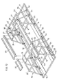
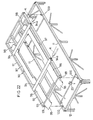
- Fig. 2 is a perspective view showing the box frame 10 with most of its accessory parts removed to facilitate understanding of the structure of the box frame 10.
- the car loading apparatus of this embodiment is used in the following manner.
- a car X is carried into the box frame 10, which has been assembled outside a container C, with the accessory parts for loading a car on the upper deck removed and with the rear rectangular end frame 12 laid flat on the ground.
- a car-guiding ramp way 31 is placed over it.
- the car X is driven up the ramp way 31 into the box frame 10 and is stopped when it comes substantially to its center. It is then lashed to the base frame 13 with the lashing devices 23. At least two lashing devices provided diagonally of the car would be sufficient.
- the accessory parts for loading on the upper deck are mounted on the box frame 10 and a car X is carried onto the upper deck.
- a car X is carried onto the upper deck.
- a car guide ramp way of a predetermined length is put at one end thereof on the rear end rectangular frame 12 so as to extend obliquely.
- a car is driven up onto the upper deck and stopped at a predetermined position. It is then lashed to the box frame 10 with the lashing devices 23. It is necessary to provide at least two lashing devices at diagonally opposite sides of the car.
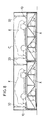
- the top of the car on the upper deck will hit the top frame F of the entrance of a container C when the car-loading apparatus is moved thereinto with two cars loaded one over the other. This is because, as shown in Fig. 7, the frame F is at a height slightly lower than the effective height of the container.
- Figs. 9 and 10 show the cars thus lashed.
- the car on the upper deck can be lowered still further from the state shown.
- the box frame 10 When the box frame 10 is not used, it can be collapsed by removing the bolts 20 and falling the side and end rectangular frames 11 and 12 inwards as shown in Fig. 11.
- the loading apparatus thus collapsed is thin, easy to carry and take up little space for storage.
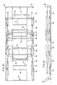
- Fig. 12 is a schematic view of the car loading apparatus of the second embodiment.
- this car loading apparatus has a base frame 13 having sufficient length and width to carry a car.
- the base frame 13 is provided with two rails 52 extending longitudinally along both side edges thereof.
- a pair of gantry frames 53 are mounted on the base frame 13 at positions corresponding to the positions of the front and rear wheels of a car carried on the base frame 13 by fixing a plurality of fixing devices 54 with rollers to the rails 52.
- the base frame 13 is provided with connecting frames 15 extending between the side frames at positions corresponding to the positions of the front and rear wheels.
- Car-mounting frames 16 spaced apart from each other by a distance equal to the wheel tread are provided to extend longitudinally across the connecting frames 15.
- Each car-mounting frame 16 is provided at its front end with a stopper 17 and has its rear end resting on a rear edge of the base frame 13.
- At least a pair of lashing devices 23 similar to those used in the first embodiment are mounted on connecting frames 58 provided perpendicular to the connecting frames 15 to lash the car at its diagonally opposite points.
- a plurality of rollers 55 are provided on the side frames of the base frame 13 at equal longitudinal intervals so that the base frame 13 is movable.
- Each gantry frame 53 has three legs at each side and a horizontal member connecting the legs at both sides and has the shape of a gate.
- the roller-carrying fixing devices 54 are secured to the bottom ends of the legs.
- the roller-carrying fixing devices 54 each comprise a U-shaped roller support 61, a roller 62, an L-shaped arm 63 secured to one side of the roller support 61, a flange 64 secured to one side of the rail 52, a fixing member 65 comprising a bolt and a nut for fixing the flange 64.
- each gantry frame 53 have the shape of a rectangle.
- Upper car-mounting frames, spaced apart from each other by a distance equal to the wheel tread, are laid across the horizontal frames 53' to extend longitudinally.
- Each upper car-mounting frame comprises a wheel support plate 26 having a stopper 27, a guide frame 29 connected to the wheel support 26, another wheel support 26, and another guide frame 30.
- the wheel supports 26 are connected to the respective horizontal frames 53'.
- the guide frames 29 and 30 are detachably mounted to the wheel supports.
- At least a pair of lashing devices 23 are provided at diagonally opposite positions of the car loaded on the upper deck to lash it. They are each secured to a longitudinal connecting member 56 of each horizontal frame 53'.
- Fig. 13 is a perspective view showing the framework of the car loading apparatus shown in Fig. 12, with one of the gantry frames 3 and the accessory parts necessary for loading a car on the upper deck all removed.
- Cars are loaded into a container by use of the car loading apparatus of this embodiment in the following manner.
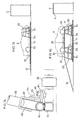
- a short ramp way 31 is set up against the base frame 13 outside a container C as shown in Fig. 15. Then a car X is driven onto the lower deck and lashed at a predetermined position by use of the lashing devices 23.
- the front gantry frame 53 is secured to the rails 52 by means of the roller-carrying fixing devices 54.
- the gantry frame is lifted with a fork lift or a crane, set on the rails 52, moved on the rails 2 by the rollers of the roller-carrying fixing devices 54 to a predetermined position and fixed.
- the gantry frames 53 may be mounted on the rails 52 before placing a car on the lower deck.
- a car X is brought up onto the upper deck.
- the rear gantry frame 53 is set in a predetermined position in the same manner as with the front gantry frame 53 and then the upper deck car-mounting frames are mounted across both the gantry frames 53.
- a long ramp way 32 is placed against the rear gantry frame 53 and a car X is driven up onto the upper deck.
- the car is then lashed to the gantry frames 53 by use of at least two lashing devices 23 provided at diagonally opposite positions of the car to fix it in a predetermined position in the same manner as in the first embodiment.
- Fig. 17 is a shematic view showing the car loading apparatus of the third embodiment.
- the apparatus of this embodiment is basically of the same structure as the the second embodiment but they differ in some details. We shall therefore describe mainly the differences from the second embodiment, while only briefly describing its basic structure.
- a base frame 13 A pair of gantry frames 53 are fixedly mounted on the base frame 13 by means of fixing members 74 of the rotatable hinge type.
- the gantry frames 53 are gate-shaped frames each comprising a horizontal frame 79 and upright frames 80 which are connected together by rotatable hinge type fixing members 74', which are, as will be described later, detachably mounted by bolts and nuts.
- vertical rods 75 are provided. Their bottom ends are in the form of rotatable hinges and their top ends have a detachable structure.
- Base frames 13 are connected together through connecting frames 15 at predetermined points.
- Right and left car-mounting frames 16 spaced apart a distance equal to the wheel tread, are mounted on the base frame 13 to extend longitudinally.
- Numeral 27 designates a stopper.
- a pair of lashing devices 23 are provided on two of the connecting rods 76 at diagonally opposite positions with respect to the car to be mounted. Rollers 77 are provided on the base frame 13 at predetermined locations.
- Each car-mounting frame comprises a wheel support 26 having a stopper 27, a guide frame 29 and another wheel support 26.
- the rear wheel supports 26 are formed with small holes 28 for engaging the front end of a ramp way, as will be described later.
- Each gantry frame 53 has a connecting rod 78 extending between overhanging frames provided at both sides of the horizontal frames 53'.
- At least a pair of lashing devices 23 for lashing the car on the upper deck are mounted on the respective connecting rods 78 at positions diagonally opposite to each other with respect to the car.
- the lashing devices 23 are used to lower the height of the car on the upper deck as with the lashing devices used in the other embodiments.
- Cars X are loaded into a container by use of the car-loading apparatus of this embodiment following the steps shown in Figs. 18 and 19.
- the upright frames 80 of one of the gantry frames 53 are brought down by detaching the fixing members 74 and the vertical rods 75.
- the horizontal frames 79 are kept connected to the upright frames 80 at one side and these frames are pulled down pivoting.
- the other gantry frame 33 is kept in the assembled condition.
- a car X is driven onto the car-mounting frames 16 from the side of the gantry frame 53 which have been collapsed, and stopped at a predetermined position. Thereafter, the car X is lashed with the lashing devices 23.
- the rear gantry frame 53 is assembled as shown in Fig. 19 and the guide frames 29 of the upper car-mounting frames are mounted on the pair of gantry frames 53. Further, the ramp way 32 is placed on the rear gantry frame 53 in the same manner as in the second embodiment.
- a car X is driven up onto the upper deck, placed at a predetermined position and lashed with the lashing devices 23 to lower the height of the car to prevent the car from hitting the entrance frame F of the container C.
- the ramp way 32 is removed and the car-loading apparatus, loaded with the two cars in two tiers, is pushed into the container by human hands in the same manner as in the other embodiments.
- the upper surface of the base frame may be made flush with the inner floor surface of the container surface by placing the base frame on an adjusting plate so that the car-loading apparatus can be moved into the container smoothly.
- One of the advantages of this embodiment is that the gantry frames 53 mounted on the base frame 13 can be disassembled and collapsed flat on the base frame 13.
- the gantry frames in the collapsed state are shown in Fig. 20.
- the car loading apparatus when not in use, can be transported with all the members other than the ramp way 32 and the guide frames 30 kept attached thereto.
- two or more loading apparatus can be piled one upon another, utilizing the guide rods 81.
- a plurality of loading apparatus can be stored in less space.
- Figs. 22 to 27 show the fourth embodiment in which an integral car loading frame is used in place of the connecting frames 24, wheel supports 26 and guide frames 29 and 30 which are employed in the first embodiment to place a car on the upper deck of the box frame.
- the upper car loading frame 90 comprises an outer frame 91, lateral frames 94 and guide frames 96 and 97, which are connected together as a single unit.
- the outer frame 91 is rectangular in shape, comprising longitudinally extending side frames and end frames provided at both ends thereof.
- the lateral frames 94 extend across the side frames 92 at positions corresponding to the positions of the front and rear wheels of the car mounted thereon.
- the lateral frames 94 are formed with openings 94a at least in both ends thereof so that the frame 90 can be lifted by a forklift with its forks inserted in the openings 94a.
- Apron guide plates 95 are secured to one of the end frames 93 of the outer frame 91 so that a car can easily climb over the end frame 93 when carried onto the frame 90.
- the guide frames 96 and 97 extend from the respective apron guide plates 95 in the longitudinal direction of the outer frame 91 at a spacing equal to the wheel tread of the car to be loaded.
- the guide frames 97 are partially cut out to prevent them from hitting the head of the car on the lower deck.
- a wheel stopper 98 is provided on the extension of each guide frame 97.
- Engaging members 99 are secured to the outer surface of the end frames 93 of the outer frame 91 at four corners thereof to set the outer frame 91 in a fixed position on the rectangular side frames 11 of the box frame 10.
- engaging members 100 are provided on the rectangular frames 11 at locations corresponding to the engaging members 99.
- the structure of the box frame is the same as that of the first embodiment.
- a car is loaded on the lower deck in exactly the same manner as in the first embodiment. Thus, its description is omitted.
- the upper car loading frame 90 After mounting the car X and inserting the forks K of the forklift L, the upper car loading frame 90 is lifted up and moved to right over the box frame 10 as shown in Fig. 23b. Then the car loading frame 90 is placed on the box frame 10 so that the engaging members 99 of the car mounting frame 40 will engage the engaging members 100 of the box frame 10.
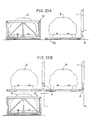
- Figs. 25 and 26 are views seen from one side and one end of the car loading frame thus placed on the box frame, respectively. In this state, the car loaded on the upper deck is lashed at diagonally opposite points in the same manner as in the first embodiment.
- a forklift is used to lift the car loading frame.
- any other lifting device such as a crane may be used to lift it.
Landscapes
- Engineering & Computer Science (AREA)
- Mechanical Engineering (AREA)
- Pallets (AREA)
Applications Claiming Priority (8)
| Application Number | Priority Date | Filing Date | Title |
|---|---|---|---|
| JP1333586A JPH03200590A (ja) | 1989-12-21 | 1989-12-21 | コンテナ用自動車積載装置 |
| JP333586/89 | 1989-12-21 | ||
| JP164981/90 | 1990-06-21 | ||
| JP16498190 | 1990-06-21 | ||
| JP179286/90 | 1990-07-04 | ||
| JP2179286A JPH0472186A (ja) | 1990-07-04 | 1990-07-04 | コンテナ用自動車積載装置 |
| JP289904/90 | 1990-10-24 | ||
| JP2289904A JPH04128175A (ja) | 1990-06-21 | 1990-10-24 | コンテナ用自動車積載装置 |
Publications (2)
| Publication Number | Publication Date |
|---|---|
| EP0435218A1 true EP0435218A1 (de) | 1991-07-03 |
| EP0435218B1 EP0435218B1 (de) | 1995-06-07 |
Family
ID=27473965
Family Applications (1)
| Application Number | Title | Priority Date | Filing Date |
|---|---|---|---|
| EP90125235A Expired - Lifetime EP0435218B1 (de) | 1989-12-21 | 1990-12-21 | Verfahren und Vorrichtung zum Laden von Fahrzeugen. |
Country Status (1)
| Country | Link |
|---|---|
| EP (1) | EP0435218B1 (de) |
Cited By (5)
| Publication number | Priority date | Publication date | Assignee | Title |
|---|---|---|---|---|
| DE4437743A1 (de) * | 1994-04-05 | 1995-10-12 | Honda Motor Co Ltd | Rückführbarer und wiederverwendbarer Kasten |
| WO2002042115A1 (en) * | 2000-11-10 | 2002-05-30 | Mærsk Container Industri As | Transportation system for containers, transportation frame and method |
| RU2346873C2 (ru) * | 2003-10-10 | 2009-02-20 | Рокко Энджиниринг Ко., Лтд. | Грузовой стеллаж |
| CN101941562A (zh) * | 2009-07-07 | 2011-01-12 | 株式会社六甲工程 | 货物用板架 |
| EP4733168A1 (de) * | 2024-10-25 | 2026-04-29 | Peter Jonathan Pieringer | Container mit radstoppern zur sicherung von fahrzeugen auf einer plattform |
Citations (3)
| Publication number | Priority date | Publication date | Assignee | Title |
|---|---|---|---|---|
| US2524260A (en) * | 1947-11-04 | 1950-10-03 | Alton W Hutson | Means for storing, handling, and transporting motor vehicles |
| FR2484340A1 (fr) * | 1980-06-13 | 1981-12-18 | Lohr Sa | Dispositif de transport et de stockage de vehicules automobiles |
| EP0274882A1 (de) * | 1986-12-18 | 1988-07-20 | G & G INTELLECTUAL PROPERTIES, INC. | Vorrichtung zum Verladen von Kraftfahrzeugen in Standard-Frachtbehälter |
-
1990
- 1990-12-21 EP EP90125235A patent/EP0435218B1/de not_active Expired - Lifetime
Patent Citations (3)
| Publication number | Priority date | Publication date | Assignee | Title |
|---|---|---|---|---|
| US2524260A (en) * | 1947-11-04 | 1950-10-03 | Alton W Hutson | Means for storing, handling, and transporting motor vehicles |
| FR2484340A1 (fr) * | 1980-06-13 | 1981-12-18 | Lohr Sa | Dispositif de transport et de stockage de vehicules automobiles |
| EP0274882A1 (de) * | 1986-12-18 | 1988-07-20 | G & G INTELLECTUAL PROPERTIES, INC. | Vorrichtung zum Verladen von Kraftfahrzeugen in Standard-Frachtbehälter |
Non-Patent Citations (1)
| Title |
|---|
| PATENT ABSTRACTS OF JAPAN, vol. 10, no. 301 (M-525), 14th October 1986; & JP-A-61 115 744 (SHOJI SASAHARA) 03-06-1986 * |
Cited By (6)
| Publication number | Priority date | Publication date | Assignee | Title |
|---|---|---|---|---|
| DE4437743A1 (de) * | 1994-04-05 | 1995-10-12 | Honda Motor Co Ltd | Rückführbarer und wiederverwendbarer Kasten |
| WO2002042115A1 (en) * | 2000-11-10 | 2002-05-30 | Mærsk Container Industri As | Transportation system for containers, transportation frame and method |
| RU2346873C2 (ru) * | 2003-10-10 | 2009-02-20 | Рокко Энджиниринг Ко., Лтд. | Грузовой стеллаж |
| CN101941562A (zh) * | 2009-07-07 | 2011-01-12 | 株式会社六甲工程 | 货物用板架 |
| CN101941562B (zh) * | 2009-07-07 | 2014-02-19 | 株式会社六甲工程 | 货物用板架 |
| EP4733168A1 (de) * | 2024-10-25 | 2026-04-29 | Peter Jonathan Pieringer | Container mit radstoppern zur sicherung von fahrzeugen auf einer plattform |
Also Published As
| Publication number | Publication date |
|---|---|
| EP0435218B1 (de) | 1995-06-07 |
Similar Documents
| Publication | Publication Date | Title |
|---|---|---|
| US5253975A (en) | Car loading apparatus | |
| KR950000582B1 (ko) | 화물운송용 표준형 밀폐구조체 속으로의 자동차 적재시스템 | |
| US4077532A (en) | Airborne cargo container transporter and transfer system | |
| US5106246A (en) | Movable platform for storing freight and automobiles | |
| US4512473A (en) | Adjustable shipping container for frangible sheet-like units | |
| US4834000A (en) | Load and roll pallet | |
| TWI656078B (zh) | 自動裝貨設備及貨物的裝貨方法 | |
| RU2700907C2 (ru) | Отдельный универсальный съемный грузовой поддон для автовоза | |
| US5016541A (en) | Greenhouse transport system | |
| CN119365393A (zh) | 集装箱内汽车的货架系统 | |
| EP0435218A1 (de) | Verfahren und Vorrichtung zum Laden von Fahrzeugen | |
| JPS6253379B2 (de) | ||
| JPH02227343A (ja) | 自動車運搬装置及び方法 | |
| CN116891137A (zh) | 托盘运输工具 | |
| US5032044A (en) | Light weight stowable front wheel seats for hauling large semistacked highway trucks in railroad cars of extraordinary height | |
| EP3498632B1 (de) | Automobiltransportrahmen zur verwendung in einem behälter und behälter damit | |
| WO2017129934A1 (en) | Vehicle transportation systems, sub-frames therefor and methods of loading vehicles into a shipping container | |
| JPS62130908A (ja) | 車台格納設備 | |
| KR950014413B1 (ko) | 컨테이너용 자동차 적재장치 | |
| KR100679464B1 (ko) | 특장차량의 리프팅장치 | |
| JPH0472186A (ja) | コンテナ用自動車積載装置 | |
| JPH0858736A (ja) | 折り畳み式コンテナの自動組立機 | |
| US4090722A (en) | Apparatus for removal of container carriers | |
| JPH0646882Y2 (ja) | 自動倉庫 | |
| JPH041247Y2 (de) |
Legal Events
| Date | Code | Title | Description |
|---|---|---|---|
| PUAI | Public reference made under article 153(3) epc to a published international application that has entered the european phase |
Free format text: ORIGINAL CODE: 0009012 |
|
| AK | Designated contracting states |
Kind code of ref document: A1 Designated state(s): DE GB IT NL |
|
| 17P | Request for examination filed |
Effective date: 19911126 |
|
| 17Q | First examination report despatched |
Effective date: 19940310 |
|
| GRAA | (expected) grant |
Free format text: ORIGINAL CODE: 0009210 |
|
| PUAC | Information related to the publication of a b1 document modified or deleted |
Free format text: ORIGINAL CODE: 0009299EPPU |
|
| STAA | Information on the status of an ep patent application or granted ep patent |
Free format text: STATUS: THE APPLICATION HAS BEEN WITHDRAWN |
|
| AK | Designated contracting states |
Kind code of ref document: B1 Designated state(s): DE GB IT NL |
|
| DB1 | Publication of patent cancelled | ||
| 18W | Application withdrawn |
Withdrawal date: 19950419 |