EP0435460B1 - Stromverteilungssteuerung für Wechselrichter im Parallelbetrieb - Google Patents
Stromverteilungssteuerung für Wechselrichter im Parallelbetrieb Download PDFInfo
- Publication number
- EP0435460B1 EP0435460B1 EP90312878A EP90312878A EP0435460B1 EP 0435460 B1 EP0435460 B1 EP 0435460B1 EP 90312878 A EP90312878 A EP 90312878A EP 90312878 A EP90312878 A EP 90312878A EP 0435460 B1 EP0435460 B1 EP 0435460B1
- Authority
- EP
- European Patent Office
- Prior art keywords
- current
- power
- output
- signal
- voltage
- Prior art date
- Legal status (The legal status is an assumption and is not a legal conclusion. Google has not performed a legal analysis and makes no representation as to the accuracy of the status listed.)
- Expired - Lifetime
Links
Images
Classifications
-
- H—ELECTRICITY
- H02—GENERATION; CONVERSION OR DISTRIBUTION OF ELECTRIC POWER
- H02J—ELECTRIC POWER NETWORKS; CIRCUIT ARRANGEMENTS OR SYSTEMS FOR SUPPLYING OR DISTRIBUTING ELECTRIC POWER; SYSTEMS FOR STORING ELECTRIC ENERGY
- H02J3/00—Circuit arrangements for AC mains or AC distribution networks
- H02J3/38—Arrangements for feeding a single network from two or more generators or sources in parallel; Arrangements for feeding already energised networks from additional generators or sources in parallel
- H02J3/46—Controlling the sharing of generated power between the generators, sources or networks
-
- H—ELECTRICITY
- H02—GENERATION; CONVERSION OR DISTRIBUTION OF ELECTRIC POWER
- H02J—ELECTRIC POWER NETWORKS; CIRCUIT ARRANGEMENTS OR SYSTEMS FOR SUPPLYING OR DISTRIBUTING ELECTRIC POWER; SYSTEMS FOR STORING ELECTRIC ENERGY
- H02J1/00—Circuit arrangements for DC mains or DC distribution networks
- H02J1/10—Parallel operation of DC sources
- H02J1/102—Parallel operation of DC sources being switching converters
-
- H—ELECTRICITY
- H02—GENERATION; CONVERSION OR DISTRIBUTION OF ELECTRIC POWER
- H02J—ELECTRIC POWER NETWORKS; CIRCUIT ARRANGEMENTS OR SYSTEMS FOR SUPPLYING OR DISTRIBUTING ELECTRIC POWER; SYSTEMS FOR STORING ELECTRIC ENERGY
- H02J1/00—Circuit arrangements for DC mains or DC distribution networks
- H02J1/10—Parallel operation of DC sources
- H02J1/108—Parallel operation of DC sources having arrangements for blocking reverse current flow, e.g. using diodes
Definitions
- This invention relates to power conversion circuits and in particular to load sharing between power circuits connected in parallel to a common load, in order to provide continuous redundant power to this load.
- Load current control feedback arrangements are used to constrain these paralleled power converters to supply substantially equal currents to a load.
- current sharing between power converters connected in parallel to a common load is accomplished by detecting a difference in currents between the paralleled converters and varying the duty cycle of the power switches to maintain load current sharing between the paralleled power converters.
- a similar load current control is disclosed in NASA technical report N76-26393/8 which discloses a method and apparatus for automatic load sharing among paralleled converters.
- a current summing and imbalance detecting circuit generate a difference signal combined with the regulating feedback signal of each converter to achieve load current sharing among the paralleled converters.
- a voltage proportional to the imbalance in current in paralleled power converters is applied through a magnitude limiting amplifier to the error amplifier input of each power converter.
- the amount of output bus voltage change that can occur as a result is limited by the saturation limit of the amplifier and by the value of the resistor limiting the output current of the amplifier.
- this amplifier permits the error amplifier to respond immediately to small output voltage imbalances. In addition, this circuit will not cause large voltage distortions when there is a transient or fault condition on the paralleling bus or when there is a large output current imbalance.
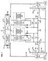
- FIG. 1 An illustrative power system including first and second power converters 110 and 210 connected in parallel to a common load is shown in FIG. 1.
- Current sharing of the current supplied by each power converter to the load is controlled by a feedback arrangement that alters the duty cycle of a power switching device in each power converter to constrain each power converter to deliver substantially equal current outputs.
- a DC input voltage source 100 is applied to the input terminals 101 and 102 of the first power converter 110.
- the output is connected through an ORing diode 111 to a load schematicly shown as a resistor 301.
- This load 301 may be a bus or other load network which is supplied by more than one power converter.
- the second power converter 210 is also connected to the common load 301 via an ORing diode 211.
- Power converter 210 is substantially identical to the first power converter 110.
- the input voltage supply 200 to power converter 210 may or may not be the same voltage input that supplies power converter 110.
- each power converter 110 and 210 The current flow of each power converter 110 and 210 is sensed by the current sensing transformers 130 and 230, respectively.
- Each power converter has an identical feedback arrangement which is operative in accord with the principles of the invention to enable output current sharing between the two converters and to constrain the resulting output bus voltage excursion.
- a current sensing winding 129 is connected to sense a current flow in a power switching device of the power converter 110.
- the winding 129 is a primary winding of sensing transformer 130.
- a secondary winding 131 supplies an AC current representative of the AC current in the power converter 110.
- the secondary winding 131 is connected through a diode 136 to a small value resistor 137 operative to assure that the secondary winding develops a peak voltage proportional to the peak current in the power converter.
- a second diode 132 connects the secondary winding 131 to a relatively large time constant circuit comprising a paralleled resistor 134 and capacitor 133.
- This network will maintain a DC voltage on the capacitor 133 proportional to the peak current in the power converter 110.
- Resistor 234 and capacitor 233 similarly maintain a DC voltage proportional to the current in power converter 210.
- the series connection of capacitor 133 and capacitor 233 result in voltages at leads 139 and 239 proportional to the difference between the currents of the two power converters 110 and 210.
- Lead 139 connects the signal proportional to the difference in current to a magnitude limiting inverting amplifier 140.
- Amplifier 140 is a simple diode transistor amplifier. The amplifier 140 is inserted in the feedback loop to increase feedback gain and hence sensitivity to small load current differences. It also has a limited output range so that it is insensitive to large differences that occur during transients.
- Amplifier 140 applies its output signal to the input of the error amplifier 161 and to the central node of the bus voltage sensing divider 150 through a resistor 141 that limits the maximum magnitude of the change in the output bus voltage. If a voltage feedback loop is included for each power converter circuit, its voltage signal representative of the output voltage would be applied through the voltage divider 150 to the inverting input of error amplifier 161. In the power converter circuit 110 it would be applied to terminal 164 and summed with the output of amplifier 140.
- error amplifier 161 The non-inverting input of error amplifier 161 is connected to the reference voltage source 105.
- the polarity of the current sensing circuitry, the inverting amplifier and the error amplifier all result in feedback of the proper polarity to ensure that the differences in output currents will be corrected.
- the polarity of any two may be inverted while still maintaining the proper feedback polarity to effect load sharing.
- An identical control arrangement is included with the power converter 210 and includes the peak voltage detection circuitry including capacitor 233, the high gain magnitude limiting amplifier circuit 240, and the error amplifier 261.
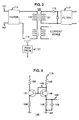
- FIG. 2 A power converter suitable for application to the parallel power system of FIG. 1 is disclosed in FIG. 2.
- the power converter circuit of FIG. 2 has a DC voltage input at input terminals 101 and 102.
- the power converter 110 includes an input filter 111 which is connected to a power switching circuit including a MOSFET power switching device 115 and the primary winding 119 of a power transformer 120.
- a secondary winding 121 is connected, via rectifying diode 113, to an output filter 117 which in turn is connected to a load or bus shown as resistor 301 in FIG. 1.
- This load may be a bus or other load network which is supplied by more than one power converter.
- the MOSFET power switching device 115 in power converter 110 is controlled by a feedback control that operates in response to the peak current attained by the MOSFET power switching device 115 in each cycle.
- the peak current attained is controlled by periodically switching the MOSFET power switching device non-conducting when a peak current level is detected. This switching is in response to the pulse width modulated drive circuit 121, which is responsive to error amplifier 161 shown in FIG. 1.
- a transistor diode amplifier suitable for use as the amplifier 140 and 240 shown in FIG. 1, is schematically shown in FIG. 3.
- This amplifier has a current mirror configuration and provides both the needed limiting function to prevent bus voltage glitch and a high gain to provide the sensitivity to small load current differences.
- Amplifier circuit 140 includes a NPN transistor 146 having its collector connected to its lead base by lead 149. Its collector is also connected to a supply voltage at terminal 175, via a resistor 145. Its emitter is connected to a ground return 167, via a resistor 148. Resistor 148 is shunted by a voltage storage capacitor 159 which is connected by lead 139 to the voltage storage capacitor 133 (shown in FIG. 1).
- the base of transistor 146 is connected to the base of a transistor 151.
- a resistor 155 connects the collector of transistor 151 to the inverting input of an error amplifier 161 (shown in FIG. 1). Its emitter is connected to the ground return 167, via resistor 158.
- the inverting input of error amplifier 161 (shown in FIG. 1) is also connected to the central node of a voltage divider 150 including resistors 162 and 163. Resistor 163 is connected to a voltage at terminal 164 which may be a voltage regulation control voltage. Resistor 162 is connected to the return ground. Its non-inverting input is connected to the reference voltage source 105.
- the error voltage output generated by the error amplifier 161 is coupled by lead 166 to a pulse width modulation drive 121 (as shown in FIG. 2) in order to control a duty cycle of the power conversion circuit 110.
- the amplifier 140 shown in FIG. 3 operates as a current mirror. By controlling the current in the transistor 151 in response to the current in transistor 146 the voltage applied to the inverting input of error amplifier 161 is modified to achieve a load current balance between power converters 110 and 210.
Landscapes
- Engineering & Computer Science (AREA)
- Power Engineering (AREA)
- Dc-Dc Converters (AREA)
- Supply And Distribution Of Alternating Current (AREA)
- Direct Current Feeding And Distribution (AREA)
Claims (3)
- Stromrichter zur Stromteilung mit gleichen Stromrichtern, wenn er zu diesen parallel geschaltet ist, mit einem Leistungsschalter (115) zur periodischen Verbindung von Energie von einem Eingang zu einem Ausgang, und Schaltungen (130-161) zum Erzeugen eines Leistungsschaltersteuersignals zum Regeln der Energieübertragung vom Eingang zum Ausgang, mit Strommeßschaltungen (130, 132, 133, 134, 136, 137) zum Messen eines Kraftstromsignals des Stromrichters in einer Energieübertragung vom Eingang zum Ausgang und zum Ausgleichen des Kraftstromsignals durch ein externes Kraftstromsignal von den gleichartigen Stromrichtern, wenn er dazu parallel geschaltet ist, um ein ausgeglichenes Strommeßsignal zu erzeugen, und Schaltungen (140, 150) zum Anlegen des ausgeglichenen Strommeßsignals an einen Fehlerverstärker (161) zum Vergleichen desselben mit einem Bezugssignal (105), dadurch gekennzeichnet, daß die Anlegeschaltungen einen Dioden-Transistor-Stromverstärker (140) mit einer Eingangsdiodenvorrichtung (146) und einer Ausgangstransistorvorrichtung (151) umfassen, die das Umwandeln von kleinen ausgeglichenen Strommeßsignalen in ein Fehlersignal und ein Begrenzen von großen ausgeglichenen Strommeßsignalen zur Begrenzung von Spannungsausschlägen am Ausgang bewirken.
- Stromrichter nach Anspruch 1, wobei die Strommeßschaltungen einen Stromwandler (130) mit einer Strommeß-Primärwicklung (129) in Reihe mit dem Leistungsschalter (115) und einer mit einer Gleichrichtdiode (132) verbundene Sekundärwicklung (131), einen Speicherkondensator (133) zum Speichern einer zum Kraftstromsignal proportionalen Spannung und einen den Speicherkondensator überbrückenden Entladungswiderstand (134), wobei der Speicherkondensator mit einem ersten Belag an die Gleichrichtdiode (132) und an einen Schaltungsknoten (135) angeschlossen ist, der zur Verbindung mit einem zweiten Speicherkondensator (233) zum Speichern einer zu einem Kraftstrom eines zweiten Stromrichters proportionalen Spannung verbunden ist, und mit einem zweiten Belag an die Anlegeschaltungen angeschlossen ist.
- Stromrichter nach Anspruch 1 oder 2, wobei ein erster Spannungsteiler (150) an einem Eingang an den Fehlerverstärker (161) angeschlossen ist und die Ausgangstransistorvorrichtung (151) zum Verändern des Teilungsverhältnisses des Spannungsteilers geschaltet ist.
Applications Claiming Priority (2)
| Application Number | Priority Date | Filing Date | Title |
|---|---|---|---|
| US07/458,009 US5036452A (en) | 1989-12-28 | 1989-12-28 | Current sharing control with limited output voltage range for paralleled power converters |
| US458009 | 1989-12-28 |
Publications (3)
| Publication Number | Publication Date |
|---|---|
| EP0435460A2 EP0435460A2 (de) | 1991-07-03 |
| EP0435460A3 EP0435460A3 (en) | 1992-04-15 |
| EP0435460B1 true EP0435460B1 (de) | 1995-04-12 |
Family
ID=23818990
Family Applications (1)
| Application Number | Title | Priority Date | Filing Date |
|---|---|---|---|
| EP90312878A Expired - Lifetime EP0435460B1 (de) | 1989-12-28 | 1990-11-27 | Stromverteilungssteuerung für Wechselrichter im Parallelbetrieb |
Country Status (4)
| Country | Link |
|---|---|
| US (1) | US5036452A (de) |
| EP (1) | EP0435460B1 (de) |
| JP (1) | JP2679868B2 (de) |
| DE (1) | DE69018600T2 (de) |
Cited By (1)
| Publication number | Priority date | Publication date | Assignee | Title |
|---|---|---|---|---|
| US8421389B2 (en) | 2006-06-15 | 2013-04-16 | Lenze Drives Gmbh | Driving with inverters with low switching losses |
Families Citing this family (58)
| Publication number | Priority date | Publication date | Assignee | Title |
|---|---|---|---|---|
| CA2053382C (en) * | 1991-10-11 | 2000-04-18 | Tom Lavrisa | Voltage booster |
| US5245525A (en) * | 1991-10-24 | 1993-09-14 | Sundstrand Corporation | DC current control through an interphase transformer using differential current sensing |
| US5193054A (en) * | 1991-10-24 | 1993-03-09 | Sundstrand Corporation | DC content control in a dual VSCF converter system |
| US5319536A (en) * | 1991-12-17 | 1994-06-07 | International Business Machines Corporation | Power system for parallel operation of AC/DC convertrs |
| US5477132A (en) * | 1992-01-10 | 1995-12-19 | Space Systems/Loral, Inc. | Multi-sectioned power converter having current-sharing controller |
| JPH05316721A (ja) * | 1992-05-07 | 1993-11-26 | Fujitsu Ltd | 並列制御型dc/dcコンバータ |
| JP2751962B2 (ja) * | 1992-10-01 | 1998-05-18 | ネミック・ラムダ株式会社 | スイッチング電源装置 |
| EP0599410B1 (de) * | 1992-11-25 | 1999-03-10 | Trt Lucent Technologies | System für Parallelschaltung von Energiewandleren |
| ATE150231T1 (de) * | 1993-01-21 | 1997-03-15 | Lambda Electronics Inc | Überlastschutz eines schaltnetzteiles |
| ES2056734B1 (es) * | 1993-01-29 | 1997-06-01 | Alcatel Standard Electrica | Sistema de conversion de potencia. |
| US5428523A (en) * | 1993-03-30 | 1995-06-27 | Ro Associates | Current sharing signal coupling/decoupling circuit for power converter systems |
| US5363323A (en) * | 1993-08-11 | 1994-11-08 | International Business Machines Corporation | Power supply with plural outputs supplying dynamic and steady loads |
| US5563540A (en) * | 1993-09-17 | 1996-10-08 | International Business Machines Corporation | Electronic switch having programmable means to reduce noise coupling |
| US5521809A (en) * | 1993-09-17 | 1996-05-28 | International Business Machines Corporation | Current share circuit for DC to DC converters |
| US5376830A (en) * | 1993-09-17 | 1994-12-27 | International Business Machines Corporation | High frequency slope compensation circuit for current programmed converter |
| US5604669A (en) * | 1995-03-28 | 1997-02-18 | Northrop Grumman Corporation | Resonant, current mode regulated, half-bridge power supply |
| EP0741447A3 (de) * | 1995-05-04 | 1997-04-16 | At & T Corp | Verfahren und Vorrichtung zur Steuerung einer Synchrongleichrichterumwandlerschaltung |
| US5650715A (en) * | 1996-04-19 | 1997-07-22 | Intel Corporation | Method and apparatus for sensing current in power supplies |
| US7269034B2 (en) | 1997-01-24 | 2007-09-11 | Synqor, Inc. | High efficiency power converter |
| JP2002514378A (ja) | 1997-01-24 | 2002-05-14 | シンクォール・インコーポレーテッド | 高効率電力変換装置 |
| US5834925A (en) * | 1997-05-08 | 1998-11-10 | Cisco Technology, Inc. | Current sharing power supplies with redundant operation |
| JP2000295763A (ja) * | 1999-03-31 | 2000-10-20 | Toshiba Corp | 多重化電源装置 |
| US6118680A (en) * | 1999-05-28 | 2000-09-12 | Peco Ii | Methods and apparatus for load sharing between parallel inverters in an AC power supply |
| JP2001008452A (ja) * | 1999-06-21 | 2001-01-12 | Sony Corp | 電源装置 |
| CA2385145A1 (en) * | 1999-10-01 | 2001-04-12 | Online Power Supply, Inc. | Non-saturating magnetic element(s) power converters and surge protection |
| US6272025B1 (en) | 1999-10-01 | 2001-08-07 | Online Power Supply, Inc. | Individual for distributed non-saturated magnetic element(s) (referenced herein as NSME) power converters |
| US6278624B1 (en) * | 1999-12-01 | 2001-08-21 | Hewlett-Packard Company | High availability DC power supply with isolated inputs, diode-or-connected outputs, and power factor correction |
| US6285571B1 (en) | 2000-03-03 | 2001-09-04 | Linfinity Microelectronics | Method and apparatus for an efficient multiphase switching regulator |
| US6292378B1 (en) | 2000-04-07 | 2001-09-18 | Linfinity Microelectronics | Method and apparatus for programmable current sharing |
| US6438007B1 (en) | 2000-05-03 | 2002-08-20 | Raymond W. Pilukaitis | Control circuit for paralleling power supplies and method of operation thereof |
| US6381155B1 (en) * | 2000-05-23 | 2002-04-30 | Next Power Corporation | Method for clusterized power sharing conversion and regulation of the primary power source within a converting and regulating power supply, and system |
| US6456510B1 (en) * | 2000-08-31 | 2002-09-24 | Compaq Computer Corporation | Unique method of reducing losses in circuits using V2 PWM control |
| JP3961812B2 (ja) * | 2001-10-31 | 2007-08-22 | 富士通株式会社 | 電源装置及びその制御方法 |
| US6965219B2 (en) * | 2002-06-28 | 2005-11-15 | Microsemi Corporation | Method and apparatus for auto-interleaving synchronization in a multiphase switching power converter |
| US7005835B2 (en) | 2002-06-28 | 2006-02-28 | Microsemi Corp. | Method and apparatus for load sharing in a multiphase switching power converter |
| US6836103B2 (en) * | 2002-06-28 | 2004-12-28 | Microsemi Corporation | Method and apparatus for dithering auto-synchronization of a multiphase switching power converter |
| US6952355B2 (en) | 2002-07-22 | 2005-10-04 | Ops Power Llc | Two-stage converter using low permeability magnetics |
| US6686726B1 (en) * | 2002-08-08 | 2004-02-03 | Innoveta Technologies, Inc. | Tracking or independent output voltage adjustment for multiple output supplies |
| US6894466B2 (en) * | 2003-02-28 | 2005-05-17 | Astec International Limited | Active current sharing circuit |
| US8730695B1 (en) | 2006-03-02 | 2014-05-20 | Ocean Server Technology, Inc. | Load balancing method and system to scale DC output power by temperature of parallel DC power supplies |
| US7569998B2 (en) | 2006-07-06 | 2009-08-04 | Microsemi Corporation | Striking and open lamp regulation for CCFL controller |
| JP2008178226A (ja) * | 2007-01-18 | 2008-07-31 | Fujitsu Ltd | 電源装置および負荷装置への電源電圧の供給方法 |
| DE102007049774B3 (de) * | 2007-10-17 | 2009-07-02 | Siemens Ag | Wechselrichter, insbesondere Solarwechselrichter, mit Lastausgleichsregelung |
| JP4666010B2 (ja) * | 2008-06-12 | 2011-04-06 | セイコーエプソン株式会社 | 負荷駆動回路及びインクジェットプリンター |
| US8093839B2 (en) * | 2008-11-20 | 2012-01-10 | Microsemi Corporation | Method and apparatus for driving CCFL at low burst duty cycle rates |
| EP2830205A3 (de) * | 2013-04-18 | 2015-03-18 | Bel Fuse (Macao Commercial Offshore) Ltd. (MCO) | Schaltnetzteil mit Temperatur- und Stromteilung |
| US10199950B1 (en) | 2013-07-02 | 2019-02-05 | Vlt, Inc. | Power distribution architecture with series-connected bus converter |
| US9857812B2 (en) | 2014-08-01 | 2018-01-02 | General Electric Company | Systems and methods for advanced diagnostic in modular power converters |
| CN106469993B (zh) * | 2016-11-22 | 2019-05-14 | 江苏通灵电器股份有限公司 | 基于电流均衡的直流并联堆叠式微型逆变器系统及控制方法 |
| US11165335B2 (en) | 2019-12-13 | 2021-11-02 | Semiconductor Components Industries, Llc | Non-regulated power converter with current sharing control |
| TWI748525B (zh) * | 2020-06-18 | 2021-12-01 | 康舒科技股份有限公司 | 提升均流調校精準度的電源供應裝置 |
| US11852691B2 (en) | 2021-08-24 | 2023-12-26 | Rockwell Automation Technologies, Inc. | Input/output (IO) module power supply with online load test capability |
| US11860599B2 (en) | 2021-09-27 | 2024-01-02 | Rockwell Automation Technologies, Inc. | High availability redundant power distribution system diagnostic operations |
| US11899445B2 (en) * | 2021-09-27 | 2024-02-13 | Rockwell Automation Technologies, Inc. | High availability redundant power distribution systems and methods |
| US11994962B2 (en) | 2021-11-04 | 2024-05-28 | Rockwell Automation Technologies, Inc. | Concurrent operation of input/output (IO) modules in a duplex configuration |
| US12068692B2 (en) | 2021-12-15 | 2024-08-20 | Raytheon Company | Multi slope output impedance controller to reduce current imbalance in a masterless configuration of n parallel-connected power converters and improve load regulation in a single power converter |
| TWI872415B (zh) * | 2021-12-15 | 2025-02-11 | 美商雷神公司 | 減少n個並聯連接電力轉換器的無主組態中電流失衡及改善單一電力轉換器中負載調節的多斜率輸出阻抗控制器 |
| US12230230B2 (en) | 2022-11-15 | 2025-02-18 | Rockwell Automation Technologies, Inc. | Systems and methods of fault detection for input/output modules of industrial systems |
Family Cites Families (11)
| Publication number | Priority date | Publication date | Assignee | Title |
|---|---|---|---|---|
| US4276590A (en) * | 1979-04-30 | 1981-06-30 | The Perkin-Elmer Corporation | Current sharing modular power system |
| SU959054A1 (ru) * | 1981-02-27 | 1982-09-15 | Московский Ордена Ленина Энергетический Институт | Способ управлени параллельно включенными стабилизаторами посто нного напр жени |
| JPS61293168A (ja) * | 1985-05-17 | 1986-12-23 | Fujitsu Ltd | コンバ−タ並列運転時の電流バランス回路 |
| US4748340A (en) * | 1986-11-17 | 1988-05-31 | Liberty Engineering, Inc. | Load share system |
| JPS63140624A (ja) * | 1986-12-03 | 1988-06-13 | 横河電機株式会社 | 電源装置 |
| JPH0521948Y2 (de) * | 1987-02-25 | 1993-06-04 | ||
| US4754161A (en) * | 1987-07-31 | 1988-06-28 | Westinghouse Electric Corp. | Circuit and method for paralleling AC electrical power systems |
| JPH0626473B2 (ja) * | 1988-02-27 | 1994-04-06 | 富士通電装株式会社 | 電流バランス型スイッチングレギュレータ |
| NL8801255A (nl) * | 1988-05-16 | 1989-12-18 | Philips Nv | Werkwijze voor het vervaardigen van een halfgeleiderinrichting. |
| JPH0265666A (ja) * | 1988-08-31 | 1990-03-06 | Nec Corp | スイッチング電源 |
| US4924170A (en) * | 1989-01-03 | 1990-05-08 | Unisys Corporation | Current sharing modular power supply |
-
1989
- 1989-12-28 US US07/458,009 patent/US5036452A/en not_active Expired - Lifetime
-
1990
- 1990-11-14 JP JP2306383A patent/JP2679868B2/ja not_active Expired - Fee Related
- 1990-11-27 DE DE69018600T patent/DE69018600T2/de not_active Expired - Fee Related
- 1990-11-27 EP EP90312878A patent/EP0435460B1/de not_active Expired - Lifetime
Cited By (1)
| Publication number | Priority date | Publication date | Assignee | Title |
|---|---|---|---|---|
| US8421389B2 (en) | 2006-06-15 | 2013-04-16 | Lenze Drives Gmbh | Driving with inverters with low switching losses |
Also Published As
| Publication number | Publication date |
|---|---|
| EP0435460A3 (en) | 1992-04-15 |
| JPH03256532A (ja) | 1991-11-15 |
| DE69018600D1 (de) | 1995-05-18 |
| EP0435460A2 (de) | 1991-07-03 |
| JP2679868B2 (ja) | 1997-11-19 |
| DE69018600T2 (de) | 1995-08-17 |
| US5036452A (en) | 1991-07-30 |
Similar Documents
| Publication | Publication Date | Title |
|---|---|---|
| EP0435460B1 (de) | Stromverteilungssteuerung für Wechselrichter im Parallelbetrieb | |
| US4074182A (en) | Power supply system with parallel regulators and keep-alive circuitry | |
| US4425613A (en) | Forced load sharing circuit for inverter power supply | |
| US4924170A (en) | Current sharing modular power supply | |
| US4635178A (en) | Paralleled DC power supplies sharing loads equally | |
| US4328429A (en) | Method and apparatus for controlling inverters in parallel operation | |
| US5724237A (en) | Apparatus and method for sharing a load current among frequency-controlled D.C.-to-D.C. converters | |
| US4044296A (en) | Electronic voltage regulator for three-phase generators | |
| US4628433A (en) | Control circuit for diode-or connected power supplies | |
| US4278930A (en) | Current sensing circuit for power supply with series control transistor | |
| US3859583A (en) | Pulse-width modulation converter circuit providing asymmetry correction and current monitoring | |
| EP0580923A1 (de) | Schaltung zum Messen der auf reinen Spannungssollwert bezogenen Spannungsschwankungen für Fehlerverstärker enthaltende Vorrichtungen | |
| US4720758A (en) | Load dependent current limiter for the power supply of a multi-module electronic system | |
| JPH01222659A (ja) | 電流バランス型スイッチングレギュレータ | |
| US5436512A (en) | Power supply with improved circuit for harmonic paralleling | |
| US6229291B1 (en) | Current sharing control system of power supply and output voltage sensing circuit | |
| US4669039A (en) | Circuit arrangement for autoconverters | |
| US4156150A (en) | Circuit for regulating a DC voltage on which a large AC voltage is superimposed | |
| US4468722A (en) | Power supply having slope controlled output volt-ampere characteristic | |
| JPH04322129A (ja) | 電源ユニット | |
| US4677537A (en) | Converter device | |
| US4339705A (en) | Thyristor switched inductor circuit for regulating voltage | |
| US3976931A (en) | AC regulator | |
| US4652987A (en) | Regulator with rectifier IR drop compensation | |
| US4716488A (en) | Primary switched-mode power supply unit |
Legal Events
| Date | Code | Title | Description |
|---|---|---|---|
| PUAI | Public reference made under article 153(3) epc to a published international application that has entered the european phase |
Free format text: ORIGINAL CODE: 0009012 |
|
| AK | Designated contracting states |
Kind code of ref document: A2 Designated state(s): DE FR GB IT |
|
| PUAL | Search report despatched |
Free format text: ORIGINAL CODE: 0009013 |
|
| AK | Designated contracting states |
Kind code of ref document: A3 Designated state(s): DE FR GB IT |
|
| 17P | Request for examination filed |
Effective date: 19921002 |
|
| RAP3 | Party data changed (applicant data changed or rights of an application transferred) |
Owner name: AT&T CORP. |
|
| 17Q | First examination report despatched |
Effective date: 19940608 |
|
| GRAA | (expected) grant |
Free format text: ORIGINAL CODE: 0009210 |
|
| AK | Designated contracting states |
Kind code of ref document: B1 Designated state(s): DE FR GB IT |
|
| ITF | It: translation for a ep patent filed | ||
| ET | Fr: translation filed | ||
| REF | Corresponds to: |
Ref document number: 69018600 Country of ref document: DE Date of ref document: 19950518 |
|
| PLBE | No opposition filed within time limit |
Free format text: ORIGINAL CODE: 0009261 |
|
| STAA | Information on the status of an ep patent application or granted ep patent |
Free format text: STATUS: NO OPPOSITION FILED WITHIN TIME LIMIT |
|
| 26N | No opposition filed | ||
| PGFP | Annual fee paid to national office [announced via postgrant information from national office to epo] |
Ref country code: DE Payment date: 19970917 Year of fee payment: 8 |
|
| PGFP | Annual fee paid to national office [announced via postgrant information from national office to epo] |
Ref country code: GB Payment date: 19970925 Year of fee payment: 8 |
|
| PGFP | Annual fee paid to national office [announced via postgrant information from national office to epo] |
Ref country code: FR Payment date: 19980107 Year of fee payment: 8 |
|
| PG25 | Lapsed in a contracting state [announced via postgrant information from national office to epo] |
Ref country code: GB Free format text: LAPSE BECAUSE OF NON-PAYMENT OF DUE FEES Effective date: 19981127 |
|
| GBPC | Gb: european patent ceased through non-payment of renewal fee |
Effective date: 19981127 |
|
| PG25 | Lapsed in a contracting state [announced via postgrant information from national office to epo] |
Ref country code: FR Free format text: LAPSE BECAUSE OF NON-PAYMENT OF DUE FEES Effective date: 19990730 |
|
| REG | Reference to a national code |
Ref country code: FR Ref legal event code: ST |
|
| PG25 | Lapsed in a contracting state [announced via postgrant information from national office to epo] |
Ref country code: DE Free format text: LAPSE BECAUSE OF NON-PAYMENT OF DUE FEES Effective date: 19990901 |
|
| PG25 | Lapsed in a contracting state [announced via postgrant information from national office to epo] |
Ref country code: IT Free format text: LAPSE BECAUSE OF NON-PAYMENT OF DUE FEES;WARNING: LAPSES OF ITALIAN PATENTS WITH EFFECTIVE DATE BEFORE 2007 MAY HAVE OCCURRED AT ANY TIME BEFORE 2007. THE CORRECT EFFECTIVE DATE MAY BE DIFFERENT FROM THE ONE RECORDED. Effective date: 20051127 |