EP0435990B1 - Vorrichtung und installation der dünnschichtchromatographie mit perfektionierung der entwicklung - Google Patents
Vorrichtung und installation der dünnschichtchromatographie mit perfektionierung der entwicklung Download PDFInfo
- Publication number
- EP0435990B1 EP0435990B1 EP90910753A EP90910753A EP0435990B1 EP 0435990 B1 EP0435990 B1 EP 0435990B1 EP 90910753 A EP90910753 A EP 90910753A EP 90910753 A EP90910753 A EP 90910753A EP 0435990 B1 EP0435990 B1 EP 0435990B1
- Authority
- EP
- European Patent Office
- Prior art keywords
- plate
- developing
- roll
- reagent
- zone
- Prior art date
- Legal status (The legal status is an assumption and is not a legal conclusion. Google has not performed a legal analysis and makes no representation as to the accuracy of the status listed.)
- Expired - Lifetime
Links
- 238000004587 chromatography analysis Methods 0.000 title claims abstract description 35
- 238000009434 installation Methods 0.000 title abstract description 35
- 238000011161 development Methods 0.000 title abstract description 33
- 239000010409 thin film Substances 0.000 title abstract 2
- 239000003153 chemical reaction reagent Substances 0.000 claims abstract description 52
- 239000011148 porous material Substances 0.000 claims abstract description 22
- 238000000034 method Methods 0.000 claims abstract description 21
- 238000004809 thin layer chromatography Methods 0.000 claims abstract description 20
- 239000000463 material Substances 0.000 claims abstract description 7
- 230000008569 process Effects 0.000 claims abstract description 5
- 238000005470 impregnation Methods 0.000 claims description 21
- 229920000642 polymer Polymers 0.000 claims description 18
- 238000006073 displacement reaction Methods 0.000 claims description 3
- 238000003825 pressing Methods 0.000 claims description 3
- 229920005830 Polyurethane Foam Polymers 0.000 claims description 2
- 239000011496 polyurethane foam Substances 0.000 claims description 2
- 230000006872 improvement Effects 0.000 abstract description 6
- 239000000126 substance Substances 0.000 abstract description 3
- 239000002250 absorbent Substances 0.000 abstract 1
- 230000002745 absorbent Effects 0.000 abstract 1
- 239000000243 solution Substances 0.000 description 11
- FEMOMIGRRWSMCU-UHFFFAOYSA-N ninhydrin Chemical compound C1=CC=C2C(=O)C(O)(O)C(=O)C2=C1 FEMOMIGRRWSMCU-UHFFFAOYSA-N 0.000 description 8
- YBJHBAHKTGYVGT-ZKWXMUAHSA-N (+)-Biotin Chemical compound N1C(=O)N[C@@H]2[C@H](CCCCC(=O)O)SC[C@@H]21 YBJHBAHKTGYVGT-ZKWXMUAHSA-N 0.000 description 6
- QTBSBXVTEAMEQO-UHFFFAOYSA-N Acetic acid Chemical compound CC(O)=O QTBSBXVTEAMEQO-UHFFFAOYSA-N 0.000 description 6
- LFQSCWFLJHTTHZ-UHFFFAOYSA-N Ethanol Chemical compound CCO LFQSCWFLJHTTHZ-UHFFFAOYSA-N 0.000 description 6
- 230000008901 benefit Effects 0.000 description 6
- OVBPIULPVIDEAO-LBPRGKRZSA-N folic acid Chemical compound C=1N=C2NC(N)=NC(=O)C2=NC=1CNC1=CC=C(C(=O)N[C@@H](CCC(O)=O)C(O)=O)C=C1 OVBPIULPVIDEAO-LBPRGKRZSA-N 0.000 description 6
- 230000005012 migration Effects 0.000 description 6
- 238000013508 migration Methods 0.000 description 6
- 239000007921 spray Substances 0.000 description 5
- 238000005507 spraying Methods 0.000 description 5
- LXNHXLLTXMVWPM-UHFFFAOYSA-N pyridoxine Chemical compound CC1=NC=C(CO)C(CO)=C1O LXNHXLLTXMVWPM-UHFFFAOYSA-N 0.000 description 4
- QIVBCDIJIAJPQS-VIFPVBQESA-N L-tryptophane Chemical compound C1=CC=C2C(C[C@H](N)C(O)=O)=CNC2=C1 QIVBCDIJIAJPQS-VIFPVBQESA-N 0.000 description 3
- OVBPIULPVIDEAO-UHFFFAOYSA-N N-Pteroyl-L-glutaminsaeure Natural products C=1N=C2NC(N)=NC(=O)C2=NC=1CNC1=CC=C(C(=O)NC(CCC(O)=O)C(O)=O)C=C1 OVBPIULPVIDEAO-UHFFFAOYSA-N 0.000 description 3
- DFPAKSUCGFBDDF-UHFFFAOYSA-N Nicotinamide Chemical compound NC(=O)C1=CC=CN=C1 DFPAKSUCGFBDDF-UHFFFAOYSA-N 0.000 description 3
- QIVBCDIJIAJPQS-UHFFFAOYSA-N Tryptophan Natural products C1=CC=C2C(CC(N)C(O)=O)=CNC2=C1 QIVBCDIJIAJPQS-UHFFFAOYSA-N 0.000 description 3
- 229960002685 biotin Drugs 0.000 description 3
- 235000020958 biotin Nutrition 0.000 description 3
- 239000011616 biotin Substances 0.000 description 3
- 239000001913 cellulose Substances 0.000 description 3
- 229920002678 cellulose Polymers 0.000 description 3
- XTVVROIMIGLXTD-UHFFFAOYSA-N copper(II) nitrate Chemical compound [Cu+2].[O-][N+]([O-])=O.[O-][N+]([O-])=O XTVVROIMIGLXTD-UHFFFAOYSA-N 0.000 description 3
- 238000000151 deposition Methods 0.000 description 3
- 238000009792 diffusion process Methods 0.000 description 3
- 238000010790 dilution Methods 0.000 description 3
- 239000012895 dilution Substances 0.000 description 3
- 229960000304 folic acid Drugs 0.000 description 3
- 235000019152 folic acid Nutrition 0.000 description 3
- 239000011724 folic acid Substances 0.000 description 3
- 238000007654 immersion Methods 0.000 description 3
- VLKZOEOYAKHREP-UHFFFAOYSA-N n-Hexane Chemical compound CCCCCC VLKZOEOYAKHREP-UHFFFAOYSA-N 0.000 description 3
- 229960003966 nicotinamide Drugs 0.000 description 3
- 235000005152 nicotinamide Nutrition 0.000 description 3
- 239000011570 nicotinamide Substances 0.000 description 3
- 229940088594 vitamin Drugs 0.000 description 3
- 229930003231 vitamin Natural products 0.000 description 3
- 235000013343 vitamin Nutrition 0.000 description 3
- 239000011782 vitamin Substances 0.000 description 3
- XLYOFNOQVPJJNP-UHFFFAOYSA-N water Substances O XLYOFNOQVPJJNP-UHFFFAOYSA-N 0.000 description 3
- CIWBSHSKHKDKBQ-JLAZNSOCSA-N Ascorbic acid Chemical compound OC[C@H](O)[C@H]1OC(=O)C(O)=C1O CIWBSHSKHKDKBQ-JLAZNSOCSA-N 0.000 description 2
- 230000005526 G1 to G0 transition Effects 0.000 description 2
- VYPSYNLAJGMNEJ-UHFFFAOYSA-N Silicium dioxide Chemical compound O=[Si]=O VYPSYNLAJGMNEJ-UHFFFAOYSA-N 0.000 description 2
- QAOWNCQODCNURD-UHFFFAOYSA-N Sulfuric acid Chemical compound OS(O)(=O)=O QAOWNCQODCNURD-UHFFFAOYSA-N 0.000 description 2
- 229930003779 Vitamin B12 Natural products 0.000 description 2
- FAPWYRCQGJNNSJ-UBKPKTQASA-L calcium D-pantothenic acid Chemical compound [Ca+2].OCC(C)(C)[C@@H](O)C(=O)NCCC([O-])=O.OCC(C)(C)[C@@H](O)C(=O)NCCC([O-])=O FAPWYRCQGJNNSJ-UBKPKTQASA-L 0.000 description 2
- 229960002079 calcium pantothenate Drugs 0.000 description 2
- 238000011088 calibration curve Methods 0.000 description 2
- 229940117916 cinnamic aldehyde Drugs 0.000 description 2
- FDJOLVPMNUYSCM-WZHZPDAFSA-L cobalt(3+);[(2r,3s,4r,5s)-5-(5,6-dimethylbenzimidazol-1-yl)-4-hydroxy-2-(hydroxymethyl)oxolan-3-yl] [(2r)-1-[3-[(1r,2r,3r,4z,7s,9z,12s,13s,14z,17s,18s,19r)-2,13,18-tris(2-amino-2-oxoethyl)-7,12,17-tris(3-amino-3-oxopropyl)-3,5,8,8,13,15,18,19-octamethyl-2 Chemical compound [Co+3].N#[C-].N([C@@H]([C@]1(C)[N-]\C([C@H]([C@@]1(CC(N)=O)C)CCC(N)=O)=C(\C)/C1=N/C([C@H]([C@@]1(CC(N)=O)C)CCC(N)=O)=C\C1=N\C([C@H](C1(C)C)CCC(N)=O)=C/1C)[C@@H]2CC(N)=O)=C\1[C@]2(C)CCC(=O)NC[C@@H](C)OP([O-])(=O)O[C@H]1[C@@H](O)[C@@H](N2C3=CC(C)=C(C)C=C3N=C2)O[C@@H]1CO FDJOLVPMNUYSCM-WZHZPDAFSA-L 0.000 description 2
- 230000008021 deposition Effects 0.000 description 2
- 238000001514 detection method Methods 0.000 description 2
- 238000001035 drying Methods 0.000 description 2
- VIQCGTZFEYDQMR-UHFFFAOYSA-N fluphenazine decanoate Chemical compound C1CN(CCOC(=O)CCCCCCCCC)CCN1CCCN1C2=CC(C(F)(F)F)=CC=C2SC2=CC=CC=C21 VIQCGTZFEYDQMR-UHFFFAOYSA-N 0.000 description 2
- RADKZDMFGJYCBB-UHFFFAOYSA-N pyridoxal hydrochloride Natural products CC1=NC=C(CO)C(C=O)=C1O RADKZDMFGJYCBB-UHFFFAOYSA-N 0.000 description 2
- 238000011002 quantification Methods 0.000 description 2
- 235000010374 vitamin B1 Nutrition 0.000 description 2
- 239000011691 vitamin B1 Substances 0.000 description 2
- 235000019163 vitamin B12 Nutrition 0.000 description 2
- 239000011715 vitamin B12 Substances 0.000 description 2
- 235000019164 vitamin B2 Nutrition 0.000 description 2
- 239000011716 vitamin B2 Substances 0.000 description 2
- 235000019158 vitamin B6 Nutrition 0.000 description 2
- 239000011726 vitamin B6 Substances 0.000 description 2
- 235000019154 vitamin C Nutrition 0.000 description 2
- 239000011718 vitamin C Substances 0.000 description 2
- 229940011671 vitamin b6 Drugs 0.000 description 2
- GHOKWGTUZJEAQD-ZETCQYMHSA-N (D)-(+)-Pantothenic acid Chemical compound OCC(C)(C)[C@@H](O)C(=O)NCCC(O)=O GHOKWGTUZJEAQD-ZETCQYMHSA-N 0.000 description 1
- KJPRLNWUNMBNBZ-QPJJXVBHSA-N (E)-cinnamaldehyde Chemical compound O=C\C=C\C1=CC=CC=C1 KJPRLNWUNMBNBZ-QPJJXVBHSA-N 0.000 description 1
- RYGMFSIKBFXOCR-UHFFFAOYSA-N Copper Chemical compound [Cu] RYGMFSIKBFXOCR-UHFFFAOYSA-N 0.000 description 1
- AUNGANRZJHBGPY-UHFFFAOYSA-N D-Lyxoflavin Natural products OCC(O)C(O)C(O)CN1C=2C=C(C)C(C)=CC=2N=C2C1=NC(=O)NC2=O AUNGANRZJHBGPY-UHFFFAOYSA-N 0.000 description 1
- ZZZCUOFIHGPKAK-UHFFFAOYSA-N D-erythro-ascorbic acid Natural products OCC1OC(=O)C(O)=C1O ZZZCUOFIHGPKAK-UHFFFAOYSA-N 0.000 description 1
- LRHPLDYGYMQRHN-UHFFFAOYSA-N N-Butanol Chemical compound CCCCO LRHPLDYGYMQRHN-UHFFFAOYSA-N 0.000 description 1
- AUNGANRZJHBGPY-SCRDCRAPSA-N Riboflavin Chemical compound OC[C@@H](O)[C@@H](O)[C@@H](O)CN1C=2C=C(C)C(C)=CC=2N=C2C1=NC(=O)NC2=O AUNGANRZJHBGPY-SCRDCRAPSA-N 0.000 description 1
- 229930003451 Vitamin B1 Natural products 0.000 description 1
- 229930003471 Vitamin B2 Natural products 0.000 description 1
- 229930003268 Vitamin C Natural products 0.000 description 1
- 238000002835 absorbance Methods 0.000 description 1
- 230000009102 absorption Effects 0.000 description 1
- 238000010521 absorption reaction Methods 0.000 description 1
- 230000009471 action Effects 0.000 description 1
- HOPRXXXSABQWAV-UHFFFAOYSA-N anhydrous collidine Natural products CC1=CC=NC(C)=C1C HOPRXXXSABQWAV-UHFFFAOYSA-N 0.000 description 1
- 238000003556 assay Methods 0.000 description 1
- 239000011575 calcium Substances 0.000 description 1
- KJPRLNWUNMBNBZ-UHFFFAOYSA-N cinnamic aldehyde Natural products O=CC=CC1=CC=CC=C1 KJPRLNWUNMBNBZ-UHFFFAOYSA-N 0.000 description 1
- UTBIMNXEDGNJFE-UHFFFAOYSA-N collidine Natural products CC1=CC=C(C)C(C)=N1 UTBIMNXEDGNJFE-UHFFFAOYSA-N 0.000 description 1
- 230000006835 compression Effects 0.000 description 1
- 238000007906 compression Methods 0.000 description 1
- 229910052802 copper Inorganic materials 0.000 description 1
- 239000010949 copper Substances 0.000 description 1
- 239000002537 cosmetic Substances 0.000 description 1
- 238000000354 decomposition reaction Methods 0.000 description 1
- 238000001212 derivatisation Methods 0.000 description 1
- 230000000694 effects Effects 0.000 description 1
- 239000003480 eluent Substances 0.000 description 1
- 239000006260 foam Substances 0.000 description 1
- 229940014662 pantothenate Drugs 0.000 description 1
- 235000019161 pantothenic acid Nutrition 0.000 description 1
- 239000011713 pantothenic acid Substances 0.000 description 1
- 239000002861 polymer material Substances 0.000 description 1
- 239000003755 preservative agent Substances 0.000 description 1
- 230000009103 reabsorption Effects 0.000 description 1
- 229960002477 riboflavin Drugs 0.000 description 1
- 238000005096 rolling process Methods 0.000 description 1
- 238000000926 separation method Methods 0.000 description 1
- 239000000377 silicon dioxide Substances 0.000 description 1
- GFYHSKONPJXCDE-UHFFFAOYSA-N sym-collidine Natural products CC1=CN=C(C)C(C)=C1 GFYHSKONPJXCDE-UHFFFAOYSA-N 0.000 description 1
- 208000006379 syphilis Diseases 0.000 description 1
- 239000012085 test solution Substances 0.000 description 1
- 229960003495 thiamine Drugs 0.000 description 1
- DPJRMOMPQZCRJU-UHFFFAOYSA-M thiamine hydrochloride Chemical compound Cl.[Cl-].CC1=C(CCO)SC=[N+]1CC1=CN=C(C)N=C1N DPJRMOMPQZCRJU-UHFFFAOYSA-M 0.000 description 1
- 230000001988 toxicity Effects 0.000 description 1
- 231100000419 toxicity Toxicity 0.000 description 1
- 238000000825 ultraviolet detection Methods 0.000 description 1
- 238000011144 upstream manufacturing Methods 0.000 description 1
- 238000009736 wetting Methods 0.000 description 1
- 210000002268 wool Anatomy 0.000 description 1
Images


Classifications
-
- G—PHYSICS
- G01—MEASURING; TESTING
- G01N—INVESTIGATING OR ANALYSING MATERIALS BY DETERMINING THEIR CHEMICAL OR PHYSICAL PROPERTIES
- G01N30/00—Investigating or analysing materials by separation into components using adsorption, absorption or similar phenomena or using ion-exchange, e.g. chromatography or field flow fractionation
- G01N30/90—Plate chromatography, e.g. thin layer or paper chromatography
- G01N30/94—Development
Definitions
- the present invention relates to an improvement made to the stage of revealing thin layer chromatography, to a development device for implementing said improvement as well as to an installation comprising said device.
- Thin layer chromatography is a method of separation by differential migration between a stationary phase and a mobile phase.
- the thin layer has a number of advantages (notably speed of migration, use of any type of development reagent).
- the CCM has many qualitative applications both in the pharmaceutical and in the food industry. However, the CCM is open to quantitative interpretation with errors of 5 to more than 10% in some cases.
- the article in the names of N. DE KRUIF et al. describes a method for detecting preservatives in cosmetic products.
- the procedure more particularly described for this identification is a thin layer chromatographic procedure.
- Six detection reagents are described, 5 of which are sprayed and the sixth of which, because of its toxicity, is applied to the chromatographic plate using a roller covered with wool, previously immersed in said reagent; it is, in particular, specified that the application of the roller is carried out until complete wetting of the chromatographic plate.
- the object of the present invention is therefore to provide an improvement in the stage of revealing layer chromatography. thin, which responds better to the needs of the practice than the revelation methods used until now, in particular in that it has the advantage of unexpectedly improving the reproducibility and the repeatability of the techniques of layer chromatography thin, especially in their quantitative applications.
- the subject of the present invention is a process for revealing in thin layer chromatography, comprising bringing a chromatography plate to be revealed into contact with a material impregnated with a development reagent, characterized in that said contacting is carried out by pressing, in a substantially uniform manner, a porous polymer containing said developer reagent against said TLC plate to be revealed, which porous polymer has (i) sufficient absorbency to completely impregnate said chromatography plate, without immersing it during the contacting under pressure, and (ii) a capacity for reabsorption of the excess reagent, at the time of the removal of said porous polymer from said plate.
- Pressure means in the sense of the present invention, the action of pressing or pushing with effort, said pressure being able to be exerted manually or mechanically.
- Said porous polymer is resistant to the usual development reagents for chromatography.
- DSP pressure derivatization
- Such a method also has the advantage of being easily automated.
- Said polymer advantageously has a foam or sponge structure.
- said polymer is a polyurethane foam with open cells.
- it is of cylindrical shape, for example a roller or has a convex semi-cylindrical surface.
- Said device necessarily has a planar contact zone with the chromatography plate, in order to apply a substantially constant and uniform pressure on the chromatography plate, whatever the contact zone.
- the present invention further relates to an installation suitable for the stage of revealing thin layer chromatography, characterized in that it comprises, in addition to a device according to the invention, means for guiding and moving of said device and / or of the chromatography plate to be revealed.
- said installation also comprises a zone for draining the device, between the impregnation zone and the revelation zone.
- said device is advantageously a roller of cylindrical shape, comprising an axial shaft whose ends are received in guide rails extending laterally on either side of the aforementioned impregnation zones, revelation and rest.
- said installation is in the form of a box with pivoting cover, allowing access to the aforementioned areas of impregnation, revelation and rest and delimiting the aforementioned slides with the walls fixed sides of said box.
- said device when it includes means for guiding and moving the chromatography plate to be revealed, said device comprises a cylindrical roller mounted for rotation about a fixed axis and on the cylindrical surface of which is wound said porous material impregnated with said reagents and said guide means move said chromatography plate -located at a distance from said cylindrical roller chosen to ensure a determined contact pressure of the porous material on the plate and to effect the impregnation of said plate by the development reagent, in a plane tangential to said roller.
- the means for guiding the chromatography plate to be revealed are constituted by a second roller, rotating around a fixed axis, parallel to that of the first roller and vertically spaced from the latter.
- At least one of the two rollers is driven in rotation about its axis.
- the second roller has the advantage both of cooperating with the first roller in guiding said chromatography plate and of allowing the application of a uniform and homogeneous pressure, exerted by the revealing device of cylindrical shape or roller on the plaque to reveal.
- said installation comprises a reagent impregnation zone, located under the first roller.
- the cylindrical surface of the first roller is divided into several compartments or sectors, juxtaposed along the axis of the roller.
- Said impregnation zone can advantageously be compartmentalized in the same way as the roller.
- Such a zone has the advantage of allowing, on the same plate, the revealing of different chromatograms, using 2 to n developers located in the different compartments of said compartment bin.
- the means for guiding the chromatography plate consist of slides oriented in the above-mentioned plane perpendicular to the axis of the device, receiving the edges of said revelation plate or of its support. , and traction or pushing means are provided for moving said plate along the slides.
- said slides are grooves or rails mounted on a support housing of said first cited roller.
- Example 1 The results obtained in Example 1 are compared with those obtained when, under the same conditions, the development is carried out by spraying.
- Example 3 Study of the relationship between the detected signal and the quantity deposited.
- the readings were taken before revelation at 275 nm and after revelation with ninhydrin at 288 nm.
- the revelation is made on the one hand, by spray and on the other hand using the DSP (pressure diversion according to the invention).
- Example 4 Detection and quantification of water-soluble vitamins.
- Test solutions containing 9 water-soluble vitamins were prepared in increasing concentrations.
- Vitamin C 2.4g Vitamin B1: 24.6 mg Vitamin B2: 32.6 mg Vitamin B6: 24.2 mg Vitamin B12: 0.4 mg Biotin: 2.42 mg Folic acid : 4.88 mg Niacinamide: 160.6 mg Ca pantothenate: 121.2 mg Water qs: 100 ml
- the other solutions correspond to a dilution of half and a quarter of the above solution.
- the plate is air-dried, the reading is carried out in direct UV at 254 nm for vitamins B1, B2, C, and niacinamide, then at 290 nm for folic acid and vitamin B6.
- Vitamin B12 and biotin are recorded at 530 nm after DSP by a 0.1% (w / v) solution of 4-dimethyl amine-cinnamaldehyde and 1% (v / v) of sulfuric acid in ethanol.
- the calcium pantothenate is read at 375 nm after DSP, by ninhydrin.
- Example 5 Study of the pressure to be applied during the implementation of the process according to the invention.
- the 10 x 10 cellulose thin layer chromatography plates (without fluorescence) (Merck-Darmstadt-RFA) were revealed by dragendorff using the pressure diversion, in accordance with the invention, on a surface of 5 x 10 cm.
- the 4.5 mm thick polymer used was compressed for 5 seconds using weights of 500 g, 1,000 g, 2,000 g and 5,000 g as well as a pressureless revelation corresponding to a simple affixing of polymer on the plate.
- a pressure applied to the polymer corresponds to an aspiration of the reagent when this pressure is released. This is very important during applications of the weights of 1000 g and 2000 g / 50 cm2 and causes the developer to return to the polymer. This return is negligible for 5,000 g / 50 cm2 or more and nonexistent for a pressure of 500 g / 50 cm2.
- the optimum development is obtained using a pressure of 5,000 g / 50 cm 2 or 40 kg for a standard plate of 20 x 20 cm for a polymer 4.5 mm thick.
- the method according to the invention can in particular be implemented using one of the devices described below.
- the device according to the present invention represented in FIG. 2 comprises a rigid support 10 provided with a handling member (grip) 11, on which is mounted a polymer material 20, soaked with development reagent.
- said device is of square shape, with a side of 200 mm, ie of the same dimension as the chromatography plates; the polymeric material has a thickness of 4.5 mm, while the rigid support has a thickness of 20 mm.
- Said device has an inverted T shape in section and is advantageously used for applying the development reagent on a chromatography plate, as described in Example 1 above.
- said device After use, said device is stored in suitable hermetic tanks.
- FIG. 3 shows another embodiment of the device according to the invention in which the part of the rigid support 10 in contact with the polymer support 20 soaked in reagent is slightly domed.
- the device according to the present invention shown in FIG. 4, comprises a rigid support 10 ′ in the form of a roller, provided with a handling axis 11 ′ around which the porous polymeric material 20 ′ is applied, soaked with development reagent, as described in Example 1 above.
- Said device is used in particular in an installation according to the invention, as visible in FIGS. 5, 6 and 7 for applying the development reagent by rolling on a chromatography plate 30.
- a device according to the invention 1 is firstly placed in the impregnation zone A, in position 1a and is thus impregnated with development reagent; then said device is transferred to position 1b, in the draining zone B, in which the possible excess of reagent is drained, before the passage of device 1 in the development zone C, in which said reagent is released from the device and uniformly impregnates the plate to be revealed.
- FIG. 6 represents said installation, with the removable part 50a of the pivoting cover 50, which allows access to the impregnation and revelation areas, open.
- Said cover has two side edges cut into steps, said edges of the cover delimiting the slide 41 of the means 40 with the side walls 60 of the box 2, cut so as to correspond to said edges.
- FIG. 7 represents a perspective view of the installation as described in FIGS. 5 and 6.
- Figures 9 and 10 show sectional views of the installation of Figure 8.
- the reagent tank 80 filled with appropriate reagent, is placed under the roller R1; the porous polymeric strip 72 is fixed in the clamp 12 of the roller R1.
- the porous material 72 follows the shape of the roller. Arriving in the tank 80, it is continuously impregnated with reagent, during each revolution. A rotation can be performed to prepreg the material 72, in order to saturate it with reagent, before the passage of the plate P.
- the revealing plate P is placed so that its stationary phase is in contact with said porous material 72.
- the revealing takes place as the rotation takes place and the excess of reagent upstream of the revealing zone is rejected in the tank 80.
- the excess reagent after revelation is, for its part, reabsorbed by the porous material 72.
- Figure 10 shows more particularly the free end of the strip of porous material 72, and a housing X in which is housed and protected the roller R1.
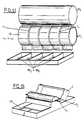
- FIG. 11 represents a roller R1 comprising, in the example shown, 5 strips (n1 to n5) of porous material 72, separated from each other by grooves r1 to r4, which strips are respectively impregnated in compartments 801 to 805 of the tank with compartmentalized reagent 80.
- This installation thus makes it possible to reveal, on the same chromatographic plate, different chromatograms using, in the embodiment shown, five different developers.
- FIG. 12 shows an embodiment of the installation in which the plate P, placed on a support guided on rails or slides 100, passes under the roller R1, rotating around the fixed axis 71.
- the spacing between the porous material 72 covering said roller and the plate P is determined to cause sufficient pressure to produce the revelation.
- the displacement of the mobile support carrying the plate P is done by pushing or pulling.
- the contact of the plate P on the roller R1 allows the rotation of the latter, and the compression of the porous material 72, the roller R1 remaining securely in place during the passage of the plate P by closing the cover C.
Landscapes
- Physics & Mathematics (AREA)
- Health & Medical Sciences (AREA)
- Life Sciences & Earth Sciences (AREA)
- Chemical & Material Sciences (AREA)
- Analytical Chemistry (AREA)
- Biochemistry (AREA)
- General Health & Medical Sciences (AREA)
- General Physics & Mathematics (AREA)
- Immunology (AREA)
- Pathology (AREA)
- Treatment Of Liquids With Adsorbents In General (AREA)
- Investigating Or Analyzing Non-Biological Materials By The Use Of Chemical Means (AREA)
Claims (17)
- Detektionsverfahren für die Dünnschicht-Chromatographie, wobei man eine Chromatographieplatte (P) zur Detektion mit einem Material, das mit einem Detektionsreagens imprägniert ist, in Kontakt bringt, dadurch gekennzeichnet, daß das Inkontaktbringen dadurch durchgeführt wird, daß man auf deutlich gleichförmige Weise ein poröses Polymeres (20, 20'; 72), das das Detektionsreagens enthält, gegen die zu detektierende DC-Platte preßt, wobei das poröse Polymere (i) eine ausreichende Absorptionskraft, um vollständig die Chromatographieplatte zu imprägnieren, ohne sie während des Inkontaktbringens unter Druck einzutauchen, und (ii) eine Kapazität zur Reabsorption von überschüssigem Reagens zum Zeitpunkt des Abziehens des porösen Polymeren von der Platte besitzt.
- Vorrichtung für die Detektion in der Dünnschicht-Chromatographie, dadurch gekennzeichnet, daß sie umfaßt:- ein poröses Polymeres (20, 20'; 72), das gegenüber den üblichen Detektionsreagentien der Chromatographie resistent ist und eine ausreichende Absorptionskraft besitzt, um vollständig eine Chromatographieplatte (P) zu imprägnieren, ohne sie zum Zeitpunkt des Inkontaktbringens unter Druck einzutauchen, und um überschüssiges Reagens während des Abziehens des porösen Materials von der Chromatographieplatte zu reabsorbieren, und- einen bezogen auf die Detektionsreagentien inerten Handhabungsträger (10, 11; 10', 11'; 70) mit einer ausreichenden Festigkeit, um die Anlegung eines geeigneten Drucks auf die Dünnschicht-Chromatographieplatte (P) zu erlauben, und auf den das poröse Material aufgebracht oder fixiert ist.
- Vorrichtung nach Anspruch 2, dadurch gekennzeichnet, daß das Polymere ein offenzelliger Polyurethanschaumstoff ist.
- Vorrichtung nach Anspruch 2 oder 3, dadurch gekennzeichnet, daß sie in zylindrischer Form, beispielsweise in Form einer Walze, vorliegt oder eine konvexe halbzylindrische Oberfläche besitzt.
- Vorrichtung nach einem der Ansprüche 2 bis 4, dadurch gekennzeichnet, daß sie rechteckige Form besitzt.
- Für die Stufe der dünnschicht-chromatographischen Detektion geeignete Einrichtung, dadurch gekennzeichnet, daß sie außer einer Vorrichtung nach einem der Ansprüche 2 bis 5 Führungselemente und Verschiebungselemente der Vorrichtung (40) und/oder der Chromatographieplatte zur Detektion (R₂, 100) umfaßt.
- Einrichtung nach Anspruch 6, dadurch gekennzeichnet, daß sie, wenn sie Elemente zur Führung und Verschiebung der Vorrichtung umfaßt, weiterhin umfaßt:- eine Imprägnierungszone (A) der Detektionsvorrichtung (1) nach einem der Ansprüche 2 bis 5;- eine Detektionszone (C), in der sich die dünnschicht-chromatographische Platte (30) zur Detektion befindet, und wobei
die Führungselemente (40) die Vorrichtung zwischen einer Position, in der sie sich in der Imprägnierungszone befindet, und einer Ruheposition (1b) verschieben, wobei die Verschiebung bewirkt, daß die Vorrichtung nach einem der Ansprüche 2 bis 5 mit der dünnschicht-chromatographischen Platte unter Druck gesetzt wird, und die Platte mit dem Detektionsreagens imprägniert wird. - Einrichtung nach Anspruch 6 oder 7, dadurch gekennzeichnet, daß sie weiterhin eine Entwässerungszone (B) der Vorrichtung zwischen der Imprägnierungszone und der Detektionszone umfaßt.
- Einrichtung nach Anspruch 7 oder 8, dadurch gekennzeichnet, daß die Vorrichtung vorteilhafterweise eine zylinderförmige Walze ist, welche eine äquatoriale Achse umfaßt, deren Enden in Führungsgleitschienen (41) münden, die sich lateral von einer Seite zur anderen der vorstehenden Imprägnierungs-, Detektions- und Ruhezonen erstrecken.
- Einrichtung nach einem der Ansprüche 6 bis 9, dadurch gekennzeichnet, daß sie in Form eines Kastens (2) mit Deckel (50) vorliegt, dessen drehbarer Teil (50a) Zutritt zu den vorstehenden Imprägnierungs-, Detektions- und Ruhezonen gewährt und die genannten Gleitelemente mit lateralen fixierten Wänden (60) des Kastens (2) begrenzt.
- Einrichtung nach Anspruch 6, dadurch gekennzeichnet, daß, wenn sie Elemente zur Führung und Verschiebung (R₂, 100) der Chromatographieplatte zur Detektion umfaßt, die Vorrichtung eine Zylinderwalze (R₁) umfaßt, die rotierend um eine feste Achse (71) angebracht ist, und auf deren zylindrischer Oberfläche das poröse Material (72), das mit den Reagentien imprägniert ist, aufgebracht ist, und die Führungselemente die Chromatographieplatte (P) - die in einer Entfernung der Zylinderwalze angebracht ist, die so gewählt ist, daß sie einen bestimmten Kontaktdruck des porösen Materials auf der Platte gewährleistet und die Imprägnierung der Platte durch das Detektionsreagens gewährleistet - in tangentialer Richtung der Walze verschieben.
- Einrichtung nach Anspruch 11, dadurch gekennzeichnet, daß die Führungselemente (R₂, 100) der Chromatographieplatte zur Detektion aus einer zweiten Walze (R₂), die um eine feste Achse (91), die parallel der der ersten Walze ist und vertikal davon abgespreizt ist, bestehen.
- Einrichtung nach Anspruch 12, dadurch gekennzeichnet, daß mindestens eine der zwei Walzen rotierend um ihre Achse angebracht ist.
- Einrichtung nach Anspruch 12 oder 13, dadurch gekennzeichnet, daß sie eine Zone zur Imprägnierung (80) mit dem Reagens, die unter der ersten Walze angebracht ist, umfaßt.
- Einrichtung nach einem der Ansprüche 12 bis 14, dadurch gekennzeichnet, daß die zylindrische Oberfläche der ersten Walze in mehrere Kompartimente oder Sektoren, die entlang der Achse der Walze angebracht sind, aufgeteilt ist.
- Einrichtung nach einem der Ansprüche 12 bis 15, dadurch gekennzeichnet, daß die Führungselemente der Chromatographieplatte aus Gleitelementen (100) bestehen, die in der vorstehenden senkrechten Richtung zur Achse der Vorrichtung angeordnet sind, die die Ränder der Detektionsplatte oder des Trägers einnehmen, und Mittel zum Ziehen oder Drücken vorgesehen sind, um die Platte entlang der Führungselemente zu verschieben.
- Einrichtung nach Anspruch 16, dadurch gekennzeichnet, daß die Führungsschienen Rillen oder Schienen, die auf ein Gehäuse des Trägers der ersten Walze montiert sind, sind.
Priority Applications (1)
| Application Number | Priority Date | Filing Date | Title |
|---|---|---|---|
| AT9090910753T ATE104771T1 (de) | 1989-07-13 | 1990-07-11 | Vorrichtung und installation der duennschichtchromatographie mit perfektionierung der entwicklung. |
Applications Claiming Priority (5)
| Application Number | Priority Date | Filing Date | Title |
|---|---|---|---|
| FR8909527A FR2649796B1 (fr) | 1989-07-13 | 1989-07-13 | Perfectionnement apporte a l'etape de revelation de la chromatographie en couche mince, dispositif de revelation et installation comportant ledit dispositif |
| FR8909527 | 1989-07-13 | ||
| FR9001735A FR2658299B2 (fr) | 1989-07-13 | 1990-02-14 | Installation comportant un dispositif de revelation pour chromatographie en couche mince. |
| FR9001735 | 1990-02-14 | ||
| PCT/FR1990/000520 WO1991001000A1 (fr) | 1989-07-13 | 1990-07-11 | Dispositif et installation de chromatographie en couche mince avec perfectionnement de la revelation |
Publications (2)
| Publication Number | Publication Date |
|---|---|
| EP0435990A1 EP0435990A1 (de) | 1991-07-10 |
| EP0435990B1 true EP0435990B1 (de) | 1994-04-20 |
Family
ID=26227477
Family Applications (1)
| Application Number | Title | Priority Date | Filing Date |
|---|---|---|---|
| EP90910753A Expired - Lifetime EP0435990B1 (de) | 1989-07-13 | 1990-07-11 | Vorrichtung und installation der dünnschichtchromatographie mit perfektionierung der entwicklung |
Country Status (8)
| Country | Link |
|---|---|
| EP (1) | EP0435990B1 (de) |
| JP (1) | JP2921980B2 (de) |
| CA (1) | CA2035025C (de) |
| DE (1) | DE69008328T2 (de) |
| ES (1) | ES2055916T3 (de) |
| FR (1) | FR2658299B2 (de) |
| RU (1) | RU2073863C1 (de) |
| WO (1) | WO1991001000A1 (de) |
Cited By (1)
| Publication number | Priority date | Publication date | Assignee | Title |
|---|---|---|---|---|
| CN104792919A (zh) * | 2015-05-19 | 2015-07-22 | 齐齐哈尔医学院 | 恒流薄层色谱仪 |
Families Citing this family (3)
| Publication number | Priority date | Publication date | Assignee | Title |
|---|---|---|---|---|
| RU2390015C1 (ru) * | 2008-12-29 | 2010-05-20 | Государственное образовательное учреждение высшего профессионального образования "Саратовский государственный университет им. Н.Г. Чернышевского" | СПОСОБ ИЗБИРАТЕЛЬНОЙ ИДЕНТИФИКАЦИИ ТРИПТОФАНА В СМЕСИ α-АМИНОКИСЛОТ |
| CZ305107B6 (cs) * | 2010-11-24 | 2015-05-06 | Technická univerzita v Liberci | Chromatografický substrát pro tenkovrstvou chromatografii nebo pro kolonovou chromatografii |
| CN103932679B (zh) * | 2014-04-09 | 2017-01-25 | 天津大学 | 一种针对薄层层析成像系统的图像校正方法 |
Family Cites Families (1)
| Publication number | Priority date | Publication date | Assignee | Title |
|---|---|---|---|---|
| US3667917A (en) * | 1970-11-27 | 1972-06-06 | Baker Chem Co J T | Chromatography apparatus and method |
-
1990
- 1990-02-14 FR FR9001735A patent/FR2658299B2/fr not_active Expired - Lifetime
- 1990-07-11 DE DE69008328T patent/DE69008328T2/de not_active Expired - Fee Related
- 1990-07-11 ES ES90910753T patent/ES2055916T3/es not_active Expired - Lifetime
- 1990-07-11 EP EP90910753A patent/EP0435990B1/de not_active Expired - Lifetime
- 1990-07-11 JP JP2510312A patent/JP2921980B2/ja not_active Expired - Fee Related
- 1990-07-11 RU SU904895004A patent/RU2073863C1/ru active
- 1990-07-11 WO PCT/FR1990/000520 patent/WO1991001000A1/fr not_active Ceased
- 1990-07-11 CA CA002035025A patent/CA2035025C/en not_active Expired - Lifetime
Cited By (2)
| Publication number | Priority date | Publication date | Assignee | Title |
|---|---|---|---|---|
| CN104792919A (zh) * | 2015-05-19 | 2015-07-22 | 齐齐哈尔医学院 | 恒流薄层色谱仪 |
| CN104792919B (zh) * | 2015-05-19 | 2016-06-15 | 齐齐哈尔医学院 | 恒流薄层色谱仪 |
Also Published As
| Publication number | Publication date |
|---|---|
| FR2658299B2 (fr) | 1993-05-21 |
| DE69008328D1 (de) | 1994-05-26 |
| CA2035025A1 (en) | 1991-01-14 |
| JP2921980B2 (ja) | 1999-07-19 |
| DE69008328T2 (de) | 1994-10-27 |
| RU2073863C1 (ru) | 1997-02-20 |
| EP0435990A1 (de) | 1991-07-10 |
| JPH04501917A (ja) | 1992-04-02 |
| WO1991001000A1 (fr) | 1991-01-24 |
| CA2035025C (en) | 2002-06-25 |
| FR2658299A2 (fr) | 1991-08-16 |
| ES2055916T3 (es) | 1994-09-01 |
Similar Documents
| Publication | Publication Date | Title |
|---|---|---|
| US4120991A (en) | Process for mounting tissue sections with an U.V. light curable mounting medium | |
| AU607088B2 (en) | Process for immobilising a protein on a solid phase | |
| WO1997048977A3 (en) | Detection of ligand interaction with polymeric material | |
| CH619782A5 (de) | ||
| EP0435990B1 (de) | Vorrichtung und installation der dünnschichtchromatographie mit perfektionierung der entwicklung | |
| CZ296121B6 (cs) | Vícevrstevný reagencní testovací prouzek a zpusobmerení analytu ve vzorku | |
| CA1276589C (fr) | Procedes et appareils d'electrophorese preparative | |
| EP0149859B1 (de) | Photometrische Messeinrichtung für Mehrbestandteilslösungen mit veränderlichem Hintergrundsgeräusch | |
| FR2614422A1 (fr) | Electrode enzymatique et module a electrode perfectionnes et leur procede d'utilisation | |
| FR2569478A1 (fr) | Bandelette d'analyse immunologique et procede pour sa fabrication | |
| ES2081924T3 (es) | Dispositivo de ensayo de diagnostico de capas multiples para determinar la presencia de sustancias en medios liquidos. | |
| FR2510758A1 (fr) | Procede de prelevement et d'analyse par chromatographie sur plaque et dispositifs permettant sa mise en oeuvre | |
| EP1373883A1 (de) | Einrichtung zur dauerbehandlung von proben durch trennung auf einer stationären phase unter erzwungenem fluss | |
| FR2649796A1 (fr) | Perfectionnement apporte a l'etape de revelation de la chromatographie en couche mince, dispositif de revelation et installation comportant ledit dispositif | |
| DE3071402D1 (en) | A method for producing alcohol oxidase, alcohol oxidase, enzyme preparation and a method for determining the concentration of a compound in an alcohol-containing sample | |
| CH615510A5 (en) | Chemical analysis process and product for implementing this process | |
| EP0666476A1 (de) | Vorrichtung zur Immunfixierung von mehreren Proben auf einem Matrixträger | |
| FR2734178A1 (fr) | Procede et appareil pour ameliorer l'uniformite d'un rideau liquide dans un systeme d'enduction au rideau | |
| FR2481228A1 (fr) | Procede et dispositif pour assembler par pliage et collage un element tel qu'une languette sur une paroi | |
| CA2122319A1 (en) | Apparatus and Method for Determining the Integrity of Coated Paper | |
| EP3314263B1 (de) | Lateral-flow-vorrichtung mit probennahme | |
| CA1069420A (en) | Integral element for analysis of liquids | |
| EP4031867B1 (de) | Vorrichtung zur entnahme einer probe einer biologischen flüssigkeit | |
| EP0548335A1 (de) | Verfahren und Vorrichtungzur Herstellung einer Gelplatte mit mikroporöser Membran und Gelkassette. | |
| FR2860299A1 (fr) | Procede d'evaluation in vitro de la tenue et/ou du transfert d'un produit cosmetique |
Legal Events
| Date | Code | Title | Description |
|---|---|---|---|
| PUAI | Public reference made under article 153(3) epc to a published international application that has entered the european phase |
Free format text: ORIGINAL CODE: 0009012 |
|
| 17P | Request for examination filed |
Effective date: 19910219 |
|
| AK | Designated contracting states |
Kind code of ref document: A1 Designated state(s): AT BE CH DE DK ES FR GB IT LI LU NL SE |
|
| 17Q | First examination report despatched |
Effective date: 19930115 |
|
| GRAA | (expected) grant |
Free format text: ORIGINAL CODE: 0009210 |
|
| AK | Designated contracting states |
Kind code of ref document: B1 Designated state(s): AT BE CH DE DK ES FR GB IT LI LU NL SE |
|
| PG25 | Lapsed in a contracting state [announced via postgrant information from national office to epo] |
Ref country code: SE Free format text: THE PATENT HAS BEEN ANNULLED BY A DECISION OF A NATIONAL AUTHORITY Effective date: 19940420 Ref country code: DK Effective date: 19940420 |
|
| REF | Corresponds to: |
Ref document number: 104771 Country of ref document: AT Date of ref document: 19940515 Kind code of ref document: T |
|
| REF | Corresponds to: |
Ref document number: 69008328 Country of ref document: DE Date of ref document: 19940526 |
|
| ITF | It: translation for a ep patent filed | ||
| EPTA | Lu: last paid annual fee | ||
| GBT | Gb: translation of ep patent filed (gb section 77(6)(a)/1977) |
Effective date: 19940715 |
|
| REG | Reference to a national code |
Ref country code: ES Ref legal event code: FG2A Ref document number: 2055916 Country of ref document: ES Kind code of ref document: T3 |
|
| PLBE | No opposition filed within time limit |
Free format text: ORIGINAL CODE: 0009261 |
|
| STAA | Information on the status of an ep patent application or granted ep patent |
Free format text: STATUS: NO OPPOSITION FILED WITHIN TIME LIMIT |
|
| 26N | No opposition filed | ||
| PGFP | Annual fee paid to national office [announced via postgrant information from national office to epo] |
Ref country code: AT Payment date: 19970721 Year of fee payment: 8 |
|
| PGFP | Annual fee paid to national office [announced via postgrant information from national office to epo] |
Ref country code: LU Payment date: 19970805 Year of fee payment: 8 |
|
| PG25 | Lapsed in a contracting state [announced via postgrant information from national office to epo] |
Ref country code: LU Free format text: LAPSE BECAUSE OF NON-PAYMENT OF DUE FEES Effective date: 19980711 Ref country code: AT Free format text: LAPSE BECAUSE OF NON-PAYMENT OF DUE FEES Effective date: 19980711 |
|
| REG | Reference to a national code |
Ref country code: GB Ref legal event code: IF02 |
|
| REG | Reference to a national code |
Ref country code: CH Ref legal event code: PCAR Free format text: ISLER & PEDRAZZINI AG;POSTFACH 1772;8027 ZUERICH (CH) |
|
| PGFP | Annual fee paid to national office [announced via postgrant information from national office to epo] |
Ref country code: ES Payment date: 20080704 Year of fee payment: 19 Ref country code: CH Payment date: 20080715 Year of fee payment: 19 Ref country code: DE Payment date: 20080722 Year of fee payment: 19 |
|
| PGFP | Annual fee paid to national office [announced via postgrant information from national office to epo] |
Ref country code: NL Payment date: 20080731 Year of fee payment: 19 Ref country code: FR Payment date: 20080627 Year of fee payment: 19 Ref country code: IT Payment date: 20080725 Year of fee payment: 19 |
|
| PGFP | Annual fee paid to national office [announced via postgrant information from national office to epo] |
Ref country code: GB Payment date: 20080716 Year of fee payment: 19 |
|
| PGFP | Annual fee paid to national office [announced via postgrant information from national office to epo] |
Ref country code: BE Payment date: 20080814 Year of fee payment: 19 |
|
| BERE | Be: lapsed |
Owner name: *SARBACH CHRISTIAN Effective date: 20090731 Owner name: *POSTAIRE ERIC Effective date: 20090731 Owner name: *DELVORDRE PASCAL Effective date: 20090731 |
|
| REG | Reference to a national code |
Ref country code: CH Ref legal event code: PL |
|
| GBPC | Gb: european patent ceased through non-payment of renewal fee |
Effective date: 20090711 |
|
| NLV4 | Nl: lapsed or anulled due to non-payment of the annual fee |
Effective date: 20100201 |
|
| REG | Reference to a national code |
Ref country code: FR Ref legal event code: ST Effective date: 20100331 |
|
| PG25 | Lapsed in a contracting state [announced via postgrant information from national office to epo] |
Ref country code: FR Free format text: LAPSE BECAUSE OF NON-PAYMENT OF DUE FEES Effective date: 20090731 Ref country code: LI Free format text: LAPSE BECAUSE OF NON-PAYMENT OF DUE FEES Effective date: 20090731 Ref country code: CH Free format text: LAPSE BECAUSE OF NON-PAYMENT OF DUE FEES Effective date: 20090731 |
|
| PG25 | Lapsed in a contracting state [announced via postgrant information from national office to epo] |
Ref country code: GB Free format text: LAPSE BECAUSE OF NON-PAYMENT OF DUE FEES Effective date: 20090711 |
|
| PG25 | Lapsed in a contracting state [announced via postgrant information from national office to epo] |
Ref country code: DE Free format text: LAPSE BECAUSE OF NON-PAYMENT OF DUE FEES Effective date: 20100202 Ref country code: BE Free format text: LAPSE BECAUSE OF NON-PAYMENT OF DUE FEES Effective date: 20090731 |
|
| REG | Reference to a national code |
Ref country code: ES Ref legal event code: FD2A Effective date: 20090713 |
|
| PG25 | Lapsed in a contracting state [announced via postgrant information from national office to epo] |
Ref country code: ES Free format text: LAPSE BECAUSE OF NON-PAYMENT OF DUE FEES Effective date: 20090713 |
|
| PG25 | Lapsed in a contracting state [announced via postgrant information from national office to epo] |
Ref country code: IT Free format text: LAPSE BECAUSE OF NON-PAYMENT OF DUE FEES Effective date: 20090711 |
|
| PG25 | Lapsed in a contracting state [announced via postgrant information from national office to epo] |
Ref country code: NL Free format text: LAPSE BECAUSE OF NON-PAYMENT OF DUE FEES Effective date: 20100201 |