EP0436643B1 - Procede et appareil de mesure des forces de coupe de machines-outils - Google Patents
Procede et appareil de mesure des forces de coupe de machines-outils Download PDFInfo
- Publication number
- EP0436643B1 EP0436643B1 EP89911472A EP89911472A EP0436643B1 EP 0436643 B1 EP0436643 B1 EP 0436643B1 EP 89911472 A EP89911472 A EP 89911472A EP 89911472 A EP89911472 A EP 89911472A EP 0436643 B1 EP0436643 B1 EP 0436643B1
- Authority
- EP
- European Patent Office
- Prior art keywords
- medium
- force
- load cell
- load
- force transducer
- Prior art date
- Legal status (The legal status is an assumption and is not a legal conclusion. Google has not performed a legal analysis and makes no representation as to the accuracy of the status listed.)
- Expired - Lifetime
Links
Images

Classifications
-
- G—PHYSICS
- G01—MEASURING; TESTING
- G01L—MEASURING FORCE, STRESS, TORQUE, WORK, MECHANICAL POWER, MECHANICAL EFFICIENCY, OR FLUID PRESSURE
- G01L5/00—Apparatus for, or methods of, measuring force, work, mechanical power, or torque, specially adapted for specific purposes
- G01L5/16—Apparatus for, or methods of, measuring force, work, mechanical power, or torque, specially adapted for specific purposes for measuring several components of force
- G01L5/167—Apparatus for, or methods of, measuring force, work, mechanical power, or torque, specially adapted for specific purposes for measuring several components of force using piezoelectric means
-
- B—PERFORMING OPERATIONS; TRANSPORTING
- B23—MACHINE TOOLS; METAL-WORKING NOT OTHERWISE PROVIDED FOR
- B23Q—DETAILS, COMPONENTS, OR ACCESSORIES FOR MACHINE TOOLS, e.g. ARRANGEMENTS FOR COPYING OR CONTROLLING; MACHINE TOOLS IN GENERAL CHARACTERISED BY THE CONSTRUCTION OF PARTICULAR DETAILS OR COMPONENTS; COMBINATIONS OR ASSOCIATIONS OF METAL-WORKING MACHINES, NOT DIRECTED TO A PARTICULAR RESULT
- B23Q17/00—Arrangements for observing, indicating or measuring on machine tools
- B23Q17/09—Arrangements for observing, indicating or measuring on machine tools for indicating or measuring cutting pressure or for determining cutting-tool condition, e.g. cutting ability, load on tool
- B23Q17/0952—Arrangements for observing, indicating or measuring on machine tools for indicating or measuring cutting pressure or for determining cutting-tool condition, e.g. cutting ability, load on tool during machining
- B23Q17/0957—Detection of tool breakage
-
- B—PERFORMING OPERATIONS; TRANSPORTING
- B23—MACHINE TOOLS; METAL-WORKING NOT OTHERWISE PROVIDED FOR
- B23Q—DETAILS, COMPONENTS, OR ACCESSORIES FOR MACHINE TOOLS, e.g. ARRANGEMENTS FOR COPYING OR CONTROLLING; MACHINE TOOLS IN GENERAL CHARACTERISED BY THE CONSTRUCTION OF PARTICULAR DETAILS OR COMPONENTS; COMBINATIONS OR ASSOCIATIONS OF METAL-WORKING MACHINES, NOT DIRECTED TO A PARTICULAR RESULT
- B23Q17/00—Arrangements for observing, indicating or measuring on machine tools
- B23Q17/09—Arrangements for observing, indicating or measuring on machine tools for indicating or measuring cutting pressure or for determining cutting-tool condition, e.g. cutting ability, load on tool
- B23Q17/0952—Arrangements for observing, indicating or measuring on machine tools for indicating or measuring cutting pressure or for determining cutting-tool condition, e.g. cutting ability, load on tool during machining
- B23Q17/0966—Arrangements for observing, indicating or measuring on machine tools for indicating or measuring cutting pressure or for determining cutting-tool condition, e.g. cutting ability, load on tool during machining by measuring a force on parts of the machine other than a motor
Definitions
- the present invention relates generally to sensing systems for the detection of worn and broken cutting tools in machine tool centers and, in particular, to a force transducer means and to a method for measuring cutting forces associated with a machine tool.
- CNC computer numerical control
- Tool condition sensor systems use advanced algorithms to detect these characteristic changes. Such systems utilize separate, specialized algorithms to detect wear, breakage and collision, and provide separate outputs to the CNC control for each occurrence.
- Tool breakage is a sudden, catastrophic event characterized by distinct changes in force signals. These changes are not a signature per se but are a characteristic sequence of events (i.e. a fingerprint). Thus, as long as the sensor system is capable of detecting the event, it is not necessary that the accuracy of the force measurement be very high. On the other hand, the detection of tool wear requires transducers which have very little hysteresis, very good linearity, and which are extremely stable with respect to movement of the machine slide or changes over time. Thus, the weak link in present day tool condition sensor systems is obtaining good transducer output representative of the cutting forces.
- sensor systems typically utilize one or more load cells.
- the load at the tool tip can reach 10,000 pounds and, because of lever arm effects, the load on a load cell can be even higher.
- German patent DE-A-3440670 K Kunststoff attempts to measure three-axis cutting tool loads by utilizing a single axis load cell or cells and calculating the three-axis load through moment arm calculations. This method of measuring cutting forces is obviously open to the introduction of significant error. Moreover, because of the dependency on moment arms, the force transducer plate cannot be placed in or even near the plane of the cutting tool. Furthermore, because of variations in moment arm due to changes in the tool tip location for different tools, the calibration of these devices will change with each new tool tip location. Thus, application is limited.
- load sensing plates which are rectangular or ring-shaped and support multiple piezo electric sensors. These measuring elements measure forces which originate in a spindleunit or turret head mounted on the elements and these forces are transferred via the plate to the machine frame.
- a turret head on a lathe which is screwed onto a sled can be equipped with such load sensing plates.
- This document neither teaches nor suggests the use of raised force shunting pads to intentionally separate a load sensing plate from a turret head or sled at all locations along the plate except those contacting the raised force shunting pads.
- This document discloses an essentially flat surface on a load sensing plate mated with another essentially flat surface on a turret head or sled.
- two flat plates are bolted together with at least one transducer contacting each plate such that the relative deformation between the plates will be registered by the transducer and three othogonal forces will be calculated.
- the mating surfaces between the two plates are by their nature imperfect and any surface has a degree of roughness, so that there are many very small gaps in the order of micrometers in the material of the plates at the mating surface. These gaps are believed to be a source for erroneous transducer readings.
- the present invention solves the aforementioned problems associated with the prior art by providing a force transducer plate for a tool condition monitoring system suitable for integration into machine structures and for measuring the cutting forces in machine tools.
- the present invention utilizes three-axis quartz force transducers mounted in a precision flat plate located in a bolted joint of the machine structure which is in the direct force path of the forces to be measured. The principal portion of the measured force is carried by the flat plate with a small portion being carried by one or more three-axis load cells. The upper and lower surfaces of the flat plate are relieved except for raised areas around bolt holes passing through the flat plate.
- This unique geometry is based on the discovery that if a completely flat plate is used, when a load is applied on the bolts, the surface of the plate will warp and raise up until contact occurs predominantly around the bolts. However, when a machine load is applied, the contact areas of the plate will begin to creep across the surfaces of the plate. These "changing" contact areas have been identified as producing a significant amount of non-linearity and, at times, are not symmetrical in all three directions. Thus, the arrangement of the present invention allows the plate to act as a means for control of the load paths, thereby substantially reducing hysteresis and non-linearity.
- One or more three-axis load cells are located near the "known" contact area.
- a primary object of the present invention is to provide a sensor assembly for a tool condition monitoring system that is capable of accurately measuring cutting forces associated with the tool.
- Another object of the present invention is to provide a transducer plate for a tool condition sensing system for machine tools that is capable of reliably detecting worn and broken cutting tools and which is capable of so performing without a trial cut and which requires minimum operator setup.
- a further object of the present invention is to provide a force transducer plate for measuring cutting forces associated with a machine tool that minimizes hysteresis and non-linearity.
- Another object of the present invention is to provide a force transducer plate of the character referred to above that is versatile in application and whose mounting position is not limited by moment arm considerations.
- Another object of the present invention is to provide a force transducer plate for measuring cutting forces of a machine tool that directly measures both compression and shear forces within the transducer plate.
- Still a further object of the present invention resides in the provision of a force transducer plate of the character referred to above that is capable of being calibrated such that the output of the plate is substantially immune to the position of the load application point.
- Still a further object of the present invention is to provide a force transducer plate of the character referred to above that minimizes the effects of adjacent structure flexibility.
- a further object of the present invention resides in the provision of a force transducer plate that is provided with pre-load adjustment means that enables the load cells within the force transducer plate or medium to be adjusted to carry a selected pre-load.
- Still a further object of the present invention resides in the provision of a relatively simple pre-load adjuster for a force transducer medium of the character referred to above that is suitable for in-field installation and which allows the transducer medium to be machined to specified tolerances without further machining required to establish a particular pre-load.
- Figure 1 is a schematic illustration of a machine tool having the transducer medium of the present invention disposed within a bolted joint.
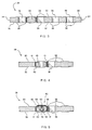
- Figure 2 is a top plan view of the force transducer medium or plate of the present invention.
- Figure 3 is a transverse sectional view taken through the lines 3-3 of Figure 2.
- Figure 4 is a sectional view taken through the lines 4-4 of Figure 2.
- Figure 5 is essentially the same view as shown in Figure 4 with the exception that a pre-load adjuster is disposed within the load cell shown.
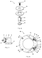
- Figure 6 is perspective exploded view of the pre-load adjuster.
- Figure 7 is a schematic illustration of a machine tool showing the force transducer medium or plate disposed in a different position within the machine tool.
- Figure 8 is plan view of an alternate transducer plate design that is suitable for the application illustrated in Figure 7.
- a machine tool is schematically shown in Figure 1 and indicated generally by the numeral 10.
- the present invention entails a system and method for measuring cutting forces associated with the machine tool 10.
- a brief description of a typical machine tool that would utilize the present invention will follow.
- machine tool 10 comprises a turret housing 12 and a turret disk 14 rotatively mounted with respect to the housing 12.
- a detachable tool holder 16 projects from the turret disk 14 and is adapted to receive and hold a cutting tool 18.
- a workpiece holder 22 is disposed adjacent tool holder 16 and is designed to receive and hold a workpiece 20.
- a cross slide 24 is secured to turret housing 12 and is movably mounted on a slide 26.
- the present invention entails the provision of a force transducer medium that is secured to or disposed within a machine tool such that cutting forces or loads associated with the cutting tool itself are transferred through the force transducer medium.
- the force transducer medium may assume various forms.
- the force transducer medium may be a plate structure that is secured within a bolted joint of the machine tool.
- the force transducer medium of the present invention could actually be integrally formed within the machine tool structure itself.
- the force transducer medium of the present invention is in the form of a force transducer plate and is indicated generally by the numeral 28.
- the force transducer plate 28 is bolted between the turret housing 12 and cross slide 24.
- the force transducer plate 28 lies in the direct path of forces associated with the cutting tool itself as these forces are transferred through the machine tool 10 and particularly through the force transducer plate 28.
- force transducer plate 28 in more detail, the same is preferably constructed of steel and includes opposed sides 30 and 32 and a surrounding edge 34. See also Figures 3-5. Formed near the perimeter of transducer plate 28 is a series of bolt openings 36. Formed around each bolt opening 36 is a raised force shunting pad 38. As seen in the drawings, it is appreciated that the force shunting pads 38 in the embodiment disclosed are raised annular rings that are elevated with respect to opposed sides 30 and 32 of the transducer plate.
- Transducer plate 28 further includes one or more load cell cavities.
- force transducer plate 28 includes two load cell cavities 40 and 42 along with associated wiring cavities 44.
- Each load cell cavity 40 and 42 is designed to accept a load cell 46.
- the number and type of load cells 46 can vary depending upon requirements and conditions. But the present invention aims at providing three axis load sensing within the plate or transducer medium itself.
- the transducer medium would include at least one three axis load cell such as Kistler 9251.
- the transducer plate 28 could be provided with a series of single axis load cells of compression and shear types which would cumulatively form a load cell network that would effectively yield three axis sensing capabilities.
- Respective load cells 46 are preferably flexibly mounted within the transducer medium or plate 28 by means of conventional sealant 41 suitable for machine tool applications.
- FIG. 3 an enlarged sectional view of the transducer plate 28 is shown illustrating the section taken along the line 3-3.
- the raised force shunting pads 38 extend above both opposed sides 30 and 32 of the plate 28.
- the raised force shunting pads 38 extend approximately 0.127 millimeters or 0.005 inches above the surface of sides 30 and 32. This distance is not critical so long as it is sufficient to prevent the bottom surface of turret housing 12 or the upper surface of cross slide 24 from contacting the opposite sides 30 and 32 of the force transducer plate 28 in either loaded or unloaded conditions.
- FIG 4 shows an enlarged sectional view of the transducer plate taken along the line 4-4 in Figure 2.
- This sectional view illustrates the relationship between the height of the load cell 46 and the raised force shunting pads 38.
- the relative height of the load cell or load cells 46 with respect to the raised force shunting pads 38 is such that the load cell is preloaded appropriately but yet not overloaded.
- the height is selected such that the load placed on the respective load cells will be approximately 4500 pounds. It should be appreciated that the height of the load cell above the raised force shunting pads can and will vary depending on the specific capacity of the load cell and its location with respect to the raised force shunting pads 38.
- the present invention provides a pre-load adjuster which is indicated generally by the numeral 50 in Figure 5 and shown in detail in Figure 6.
- a pre-load adjuster 50 which is indicated generally by the numeral 50 in Figure 5 and shown in detail in Figure 6.
- the pre-load adjuster 50 it is seen that the same includes an elongated stem 52 having a circumferential groove 54 formed in a portion thereof. Groove 54 is designed to receive an elastomeric o-ring 56.
- a fixed disk 58 is attached to one end of stem 52 by means of a fastener 60.
- Pre-load shims 62 of various selective thicknesses are provided with the pre-load adjuster 50.
- Each pre-load shim 62 includes a central opening having a sufficient diameter so as to permit stem 52 and the accompanying o-ring 56 to pass therethrough.
- Figure 5 shows a fragmentary cross-sectional view of the transducer plate 28 showing the pre-load adjuster 50 inserted within a load cell 46.
- the force transducer medium will be integrally formed or pocketed in the machine tool.
- the pre-load adjuster 50 can be provided with threads about stem 52 in order that the same can be actually anchored into associated machine tool structure.
- the stem 52 of the pre-load adjuster 50 can be secured in an upside down fashion within the bottom surface of turret housing 12.
- the engagement of the o-ring 56 with the central opening or bore of the load cell will generally be sufficient to support the load cell 46 and hold the same in place for assembly.
- the alternate force transducer plate is indicated generally by the numeral 80 and is designed to be located directly behind the curvic coupling 15 of the machine tool 10 or between the curvic coupling 15 and the turret housing 12 (See Figure 7).
- the annular force transducer plate 80 is similar in design and function as the force transducer plate shown in Figure 2 and described above. But as seen in the drawings, the annular force transducer plate is particularly designed to be disposed in a plane generally perpendicular to the plane of the force transducer plate 28 as applied in Figure 1 where plate 28 lies between the turret housing 12 and the cross slide 24. In any event, it is seen that the annular force transducer plate 80 includes the same series of bolt openings 36 and raised force shunting pads 38. Likewise, the annular force transducer plate includes load cell cavities 40 and 42 along with accompanying wiring cavities 44. A pair of load cells 46 are resiliently mounted within respective load cell cavities. The relationship between the load cells 46, raised force shunting pads 38 and the opposite sides of the annular transducer plate 80 are essentially the same as found in the force transducer plate 28 shown in Figure 2.
- the force transducer medium that has been particularly shown in the form of a plate structure could be integrally formed within the machine tool itself.
- the force transducer medium would include the same features, namely the raised force shunting pads and the selective positioning of the load cells adjacent to the raised force shunting pads. It is appreciated that the relative height differences discussed with respect to the plate structures 28 and 80 would be applicable to an integral or pocketed force transducer medium.
- a principal portion of the measured force is carried by the force transducer plate or medium via the raised force shunting pads 38 while a small portion is carried by the three axis load cell 46 which in turn provides a cutting force signal which is indicative of the forces applied to the cutting tool 18. Therefore, the load passing through the transducer plate or medium is effectively divided between the plate or medium and the respective load cells housed within the plate or medium. Consequently, this enables one to protect against load cell overloading.
- the proportionate amount of load sensed or carried by the respective load cells can be varied depending upon a number of factors including the relative area and location of the raised force shunting pads 38 as shown in Figure 2.
- the force transducer plate or medium of the present invention is capable of accurately measuring cutting forces associated with a cutting tool.
- the present method and system is capable of performing without a trial or turning cut and requires a minimum amount of setup time. Because of the design of the raised force shunting pads and the particular location and height spacing of the load cells with respect to the force shunting pads, hysteresis is minimized and linearity is optimized.
- both compression and shear forces are actually measured within the transducer plate or medium and the design does not rely on moment arms in order to measure cutting forces associated with the tool.
- the output of the force transducer plate or medium is substantially immune to load application point.
Landscapes
- Engineering & Computer Science (AREA)
- Mechanical Engineering (AREA)
- Physics & Mathematics (AREA)
- General Physics & Mathematics (AREA)
- Force Measurement Appropriate To Specific Purposes (AREA)
- Machine Tool Sensing Apparatuses (AREA)
Claims (13)
- Un milieu capteur de force (28) pour mesurer des forces de coupe associées à une machine-outil (10), comprenant:a) un milieu capteur de force (28) adapté à assumer une position dans un chemin direct de flux de force de la machine-outil (10);b) des moyens de transmission de charge ponctuelle (38) formant une partie du milieu capteur de force pour transférer une première partie des charges de coupe de force à travers des zones ponctuelles (38) du milieu capteur de force (28); etc) des moyens de cellule de mesure de charge (46) montés dans le milieu capteur de force (28) directement adjacent aux moyens de transfert de charge ponctuelle (38) pour mesurer des forces de coupe associées à la machine-outil, et dans lequel le transfert de forces de coupe à travers les zones ponctuelles (38) en association avec l'emplacement rapproché des moyens de cellule de mesure (46) par rapport aux zones ponctuelles de transfert (38) donne lieu à une hystérésis diminuée et une linéarité améliorée.
- Le milieu capteur de force suivant la revendication 1, dans lequel le milieu capteur de force (28) comporte une plaque transductrice de force ayant des côtés opposés (30, 32) avec une série d'ouvertures à boulon (36) formées dans ceux-ci; des bourrelets de dérivation de force (38) en saillie sur les deux côtés (30, 32) du milieu autour des ouvertures (36) à boulons pour transférer une partie essentielle de la charge de force de coupe à travers le milieu, tout en laissant sans charge une partie essentielle du milieu; une cavité de cellule de mesure de charge (48) formée au voisinage immédiat d'au moins un bourrelet de dérivation de force en saillie (38); et dans lequel la cellule de mesure de charge (46) est montée avec la cavité de cellule de mesure de charge (42).
- Le milieu capteur de force suivant la revendication 2, dans lequel les moyens de cellule de mesure de charge (46) comportent des moyens pour mesurer des forces de coupe selon trois axes orthogonaux, de manière telle que la compression et la force de cisaillement peuvent être directement mesurées au sein du milieu.
- Le milieu capteur de force suivant la revendication 3, dans lequel la cellule de mesure de charge (46) comporte une surface d'engagement de charge qui est située approximativement à 0,0005 pouce au-dessus des bourrelets de dérivation de force (38) en saillie.
- Le milieu capteur de force suivant la revendication 4, dans lequel les bourrelets de dérivation de force (38) sont en saillie au moins approximativement 0,005 pouce au-dessus de la surface sous-jacente (30, 32) du milieu capteur.
- Le milieu capteur de force suivant la revendication 1, dans lequel les moyens de cellule de mesure de charge (46) sont du type ayant une ouverture centrale et dans lequel un moyen d'ajustage de précharge de cellule de mesure de charge est prévu, comprenant:a) une tige (52) adaptée à être fixée à l'intérieur de l'ouverture de la cellule de mesure de charge (46);b) un moyen de retenue (58) normalement relié à une partie d'extrémité de la tige; etc) des moyens intercalaires (62) confinés autour de la tige (52) et positionnés normalement entre le moyen de retenue (58) et la cellule de mesure de charge (46) pour ajuster la hauteur effective de la cellule de mesure de charge (46) par rapport au bourrelet de dérivation de force (38) en saillie.
- Le milieu capteur de force suivant la revendication 6, dans lequel ledit moyen d'ajustage comporte un anneau en O (56) formé autour de la tige (52) et dans lequel le moyen de retenue comporte un disque fixé par une vis (60) à une extrémité de la tige (52).
- Le milieu capteur de force suivant la revendication 1, comportant des moyens (50) pour varier la hauteur effective de la cellule de mesure de charge.
- Un procédé de mesure de force de coupe associé à une machine-outil (10) qui minimise l'hystéréris et la non-linéarité comprenant:a) positionnement d'un moyen capteur de force (28) dans un chemin direct de flux de force de la machine-outil (10);b) diriger les forces de coupe à partir de la machine-outil (10) vers le moyen capteur de force (28);c) diriger les forces de coupe à travers le milieu (28) à des zones ponctuelles (38) sur le milieu (28) en laissant sans charge une partie essentielle de la surface du milieu;d) positionnement de la cellule de mesure de charge (46) au voisinage immédiat d'au moins une zone ponctuelle (38) de support de charge sur le milieu (28); ete) diriger une partie des forces de coupe à travers la cellule de mesure de charge (46) qui est adjacente à la zone ponctuelle (38) de support de charge, et mesurer celles des forces de coupe qui passent à travers la cellule de mesure de charge (46) tout en transférant simultanément une autre partie des forces de coupe à travers la zone ponctuelle (38) de support de charge, ce qui conduit à une minimisation de l'hystérésis et de la non-linéarité à cause de la charge ponctuelle choisie et l'emplacement de la cellule de mesure de charge (46) par rapport à la charge ponctuelle.
- Procédé suivant la revendication 9, dans lequel le milieu comporte une plaque transductrice (28) et le procédé comporte en outre les étapes suivantes:a) fixation à boulons du milieu capteur de force (28) à l'intérieur d'un joint;b) surélever la surface (38) du milieu capteur (28) autour de l'ouverture à boulon (36), de manière telle que les forces de coupe associées à la machine-outil (10) sont transférées à travers les surfaces surélevées (38) et non la surface entourante (30, 32) du milieu située à un niveau plus bas; etc) positionnement de la cellule de mesure de charge (46) en proximité immédiate d'au moins une surface surélevée (38) de manière telle que la charge totale transférée à travers le moyen capteur de force (28) est transférée à travers les zones surélevées du milieu et de la cellule adjacente de mesure de force (46).
- Le procédé suivant la revendication 10, comportant l'étape d'élever la surface de charge effective de la cellule de mesure de charge (46) à une hauteur un peu plus grande que la hauteur de la surface surélevée (38) du milieu capteur de force (28).
- Le procédé suivant la revendication 11, comportant l'étape de variation et ajustage de la hauteur effective de la cellule de mesure de charge (46) en ajoutant des intercalaires (62) à la cellule de mesure de charge (46) ou en enlevant des intercalaires (62) de la cellule de mesure de charge (46).
- Le procédé suivant la revendication 9, comportant l'étape de mesure des forces de coupe suivant trois axes séparés orthogonaux au sein du milieu capteur de force (28).
Applications Claiming Priority (3)
| Application Number | Priority Date | Filing Date | Title |
|---|---|---|---|
| US07/251,155 US4875365A (en) | 1988-09-29 | 1988-09-29 | Method and apparatus for measuring cutting forces of machine tool |
| US251155 | 1988-09-29 | ||
| PCT/US1989/003931 WO1990003559A1 (fr) | 1988-09-29 | 1989-09-12 | Procede et appareil de mesure des forces de coupe de machines-outils |
Publications (3)
| Publication Number | Publication Date |
|---|---|
| EP0436643A1 EP0436643A1 (fr) | 1991-07-17 |
| EP0436643A4 EP0436643A4 (en) | 1992-01-15 |
| EP0436643B1 true EP0436643B1 (fr) | 1994-05-25 |
Family
ID=22950719
Family Applications (1)
| Application Number | Title | Priority Date | Filing Date |
|---|---|---|---|
| EP89911472A Expired - Lifetime EP0436643B1 (fr) | 1988-09-29 | 1989-09-12 | Procede et appareil de mesure des forces de coupe de machines-outils |
Country Status (7)
| Country | Link |
|---|---|
| US (1) | US4875365A (fr) |
| EP (1) | EP0436643B1 (fr) |
| JP (1) | JPH04500781A (fr) |
| AT (1) | ATE106141T1 (fr) |
| CA (1) | CA1322869C (fr) |
| DE (1) | DE68915549T2 (fr) |
| WO (1) | WO1990003559A1 (fr) |
Families Citing this family (4)
| Publication number | Priority date | Publication date | Assignee | Title |
|---|---|---|---|---|
| CH680421A5 (fr) * | 1989-12-22 | 1992-08-31 | Kistler Instrumente Ag | |
| EP0708915A4 (fr) * | 1993-01-05 | 1996-08-14 | Montronix Inc | Transducteur de boulon et procede de surveillance des forces de coupe dans une machine-outil |
| EP0651239A3 (fr) * | 1993-10-29 | 1996-06-12 | Omron Tateisi Electronics Co | Capteur magnétostrictif de couple, appareil de mesure magnétostrictif de couple et appareil de surveillance de l'état d'un outil de coupe utilisant ce capteur. |
| AT520901B1 (de) * | 2018-01-24 | 2019-11-15 | Avl List Gmbh | Messvorrichtung und Verfahren zur Bestimmung einer Kraft und/oder eines Drehmoments an einer drehmomentübertragenden Welle |
Family Cites Families (6)
| Publication number | Priority date | Publication date | Assignee | Title |
|---|---|---|---|---|
| CH502590A (de) * | 1968-11-04 | 1971-01-31 | Kistler Instrumente Ag | Kraft- und/oder Momentenmessanordnung |
| US3636760A (en) * | 1970-02-25 | 1972-01-25 | Gse Inc | Force measuring apparatus |
| US3771359A (en) * | 1972-05-17 | 1973-11-13 | Gse Inc | Load cell |
| US3939704A (en) * | 1974-08-07 | 1976-02-24 | The Bendix Corporation | Multi-axis load cell |
| DE3440670C2 (de) * | 1984-11-07 | 1986-10-23 | Prometec GmbH, 5100 Aachen | Vorrichtung zum Messen der auf Maschinenbauteile wirkenden Kräfte und Momente |
| US4741231A (en) * | 1986-04-14 | 1988-05-03 | The Warner & Swasey Company | Tool force sensor and method of making same |
-
1988
- 1988-09-29 US US07/251,155 patent/US4875365A/en not_active Expired - Fee Related
-
1989
- 1989-09-12 DE DE68915549T patent/DE68915549T2/de not_active Expired - Fee Related
- 1989-09-12 WO PCT/US1989/003931 patent/WO1990003559A1/fr not_active Ceased
- 1989-09-12 JP JP1510647A patent/JPH04500781A/ja active Pending
- 1989-09-12 EP EP89911472A patent/EP0436643B1/fr not_active Expired - Lifetime
- 1989-09-12 AT AT89911472T patent/ATE106141T1/de not_active IP Right Cessation
- 1989-09-18 CA CA000611751A patent/CA1322869C/fr not_active Expired - Fee Related
Also Published As
| Publication number | Publication date |
|---|---|
| WO1990003559A1 (fr) | 1990-04-05 |
| ATE106141T1 (de) | 1994-06-15 |
| DE68915549D1 (de) | 1994-06-30 |
| EP0436643A4 (en) | 1992-01-15 |
| EP0436643A1 (fr) | 1991-07-17 |
| CA1322869C (fr) | 1993-10-12 |
| JPH04500781A (ja) | 1992-02-13 |
| US4875365A (en) | 1989-10-24 |
| DE68915549T2 (de) | 1994-09-29 |
Similar Documents
| Publication | Publication Date | Title |
|---|---|---|
| US5783751A (en) | Cutting force sensor in the form of a turret locking screw | |
| US6204771B1 (en) | Load indicating fastener systems method and apparatus | |
| AU743407B2 (en) | Load indicating fastener systems method and apparatus | |
| WO1983003471A1 (fr) | Detecteur de force, de couple et de deplacement pour machines-outils | |
| US4884461A (en) | Force sensor | |
| US20110259110A1 (en) | Device for Measuring Strain in a Component | |
| US12128516B2 (en) | Tool and method for measuring a tool force | |
| EP0436643B1 (fr) | Procede et appareil de mesure des forces de coupe de machines-outils | |
| US4899594A (en) | Device for measuring the cutting forces on machine tools | |
| Oraby et al. | High-capacity compact three-component cutting force dynamometer | |
| JPH0246349B2 (fr) | ||
| US5329823A (en) | Interposed force sensor including amplifiers | |
| Adolfsson et al. | Cutting force model for multi-toothed cutting processes and force measuring equipment for face milling | |
| US5211060A (en) | Bidirectional force sensor | |
| US4778317A (en) | Tactile sensing tool positioning system | |
| JPH0629804B2 (ja) | 力センサの過負荷保護装置 | |
| JPH01189533A (ja) | 力センサの過負荷保護装置 | |
| US3646685A (en) | Gaging head for pneumatic bore gaging devices | |
| Daneshi et al. | A split-platen pressure cell for the measurement of pressure distribution in upsetting operations | |
| US6082172A (en) | System and method for checking the quality of hammering operation on a mechanical component during the hammering operation | |
| Mackinnon et al. | A force transducer for a turret lathe | |
| JP7556972B2 (ja) | 力センサを有する切削機、この種の切削機の使用、及びこの種の切削機の力センサを較正する方法 | |
| JPH0351730A (ja) | 荷重検出器 | |
| JPH0672824B2 (ja) | 荷重検出装置 | |
| WO1994016302A1 (fr) | Transducteur de boulon et procede de surveillance des forces de coupe dans une machine-outil |
Legal Events
| Date | Code | Title | Description |
|---|---|---|---|
| PUAI | Public reference made under article 153(3) epc to a published international application that has entered the european phase |
Free format text: ORIGINAL CODE: 0009012 |
|
| 17P | Request for examination filed |
Effective date: 19910219 |
|
| AK | Designated contracting states |
Kind code of ref document: A1 Designated state(s): AT BE CH DE FR GB IT LI LU NL SE |
|
| A4 | Supplementary search report drawn up and despatched |
Effective date: 19911126 |
|
| AK | Designated contracting states |
Kind code of ref document: A4 Designated state(s): AT BE CH DE FR GB IT LI LU NL SE |
|
| 17Q | First examination report despatched |
Effective date: 19930203 |
|
| RAP1 | Party data changed (applicant data changed or rights of an application transferred) |
Owner name: MONTRONIX, INC. |
|
| GRAA | (expected) grant |
Free format text: ORIGINAL CODE: 0009210 |
|
| AK | Designated contracting states |
Kind code of ref document: B1 Designated state(s): AT BE CH DE FR GB IT LI LU NL SE |
|
| PG25 | Lapsed in a contracting state [announced via postgrant information from national office to epo] |
Ref country code: SE Free format text: THE PATENT HAS BEEN ANNULLED BY A DECISION OF A NATIONAL AUTHORITY Effective date: 19940525 Ref country code: NL Effective date: 19940525 Ref country code: LI Effective date: 19940525 Ref country code: CH Effective date: 19940525 Ref country code: BE Effective date: 19940525 Ref country code: AT Effective date: 19940525 |
|
| REF | Corresponds to: |
Ref document number: 106141 Country of ref document: AT Date of ref document: 19940615 Kind code of ref document: T |
|
| REF | Corresponds to: |
Ref document number: 68915549 Country of ref document: DE Date of ref document: 19940630 |
|
| ITF | It: translation for a ep patent filed | ||
| REG | Reference to a national code |
Ref country code: CH Ref legal event code: PL |
|
| ET | Fr: translation filed | ||
| PG25 | Lapsed in a contracting state [announced via postgrant information from national office to epo] |
Ref country code: GB Effective date: 19940912 |
|
| PG25 | Lapsed in a contracting state [announced via postgrant information from national office to epo] |
Ref country code: LU Free format text: LAPSE BECAUSE OF NON-PAYMENT OF DUE FEES Effective date: 19940930 |
|
| NLV1 | Nl: lapsed or annulled due to failure to fulfill the requirements of art. 29p and 29m of the patents act | ||
| PLBE | No opposition filed within time limit |
Free format text: ORIGINAL CODE: 0009261 |
|
| STAA | Information on the status of an ep patent application or granted ep patent |
Free format text: STATUS: NO OPPOSITION FILED WITHIN TIME LIMIT |
|
| GBPC | Gb: european patent ceased through non-payment of renewal fee |
Effective date: 19940912 |
|
| 26N | No opposition filed | ||
| PGFP | Annual fee paid to national office [announced via postgrant information from national office to epo] |
Ref country code: FR Payment date: 20000921 Year of fee payment: 12 |
|
| PGFP | Annual fee paid to national office [announced via postgrant information from national office to epo] |
Ref country code: DE Payment date: 20001128 Year of fee payment: 12 |
|
| PG25 | Lapsed in a contracting state [announced via postgrant information from national office to epo] |
Ref country code: DE Free format text: LAPSE BECAUSE OF NON-PAYMENT OF DUE FEES Effective date: 20020501 |
|
| PG25 | Lapsed in a contracting state [announced via postgrant information from national office to epo] |
Ref country code: FR Free format text: LAPSE BECAUSE OF NON-PAYMENT OF DUE FEES Effective date: 20020531 |
|
| REG | Reference to a national code |
Ref country code: FR Ref legal event code: ST |
|
| PG25 | Lapsed in a contracting state [announced via postgrant information from national office to epo] |
Ref country code: IT Free format text: LAPSE BECAUSE OF NON-PAYMENT OF DUE FEES;WARNING: LAPSES OF ITALIAN PATENTS WITH EFFECTIVE DATE BEFORE 2007 MAY HAVE OCCURRED AT ANY TIME BEFORE 2007. THE CORRECT EFFECTIVE DATE MAY BE DIFFERENT FROM THE ONE RECORDED. Effective date: 20050912 |