EP0436728A1 - Robinet melangeur pour eau chaude/froide et sa structure de fixation - Google Patents
Robinet melangeur pour eau chaude/froide et sa structure de fixation Download PDFInfo
- Publication number
- EP0436728A1 EP0436728A1 EP90910889A EP90910889A EP0436728A1 EP 0436728 A1 EP0436728 A1 EP 0436728A1 EP 90910889 A EP90910889 A EP 90910889A EP 90910889 A EP90910889 A EP 90910889A EP 0436728 A1 EP0436728 A1 EP 0436728A1
- Authority
- EP
- European Patent Office
- Prior art keywords
- control
- hot
- control knob
- cold water
- faucet body
- Prior art date
- Legal status (The legal status is an assumption and is not a legal conclusion. Google has not performed a legal analysis and makes no representation as to the accuracy of the status listed.)
- Granted
Links
Images


Classifications
-
- E—FIXED CONSTRUCTIONS
- E03—WATER SUPPLY; SEWERAGE
- E03C—DOMESTIC PLUMBING INSTALLATIONS FOR FRESH WATER OR WASTE WATER; SINKS
- E03C1/00—Domestic plumbing installations for fresh water or waste water; Sinks
- E03C1/02—Plumbing installations for fresh water
- E03C1/04—Water-basin installations specially adapted to wash-basins or baths
- E03C1/042—Arrangements on taps for wash-basins or baths for connecting to the wall
-
- E—FIXED CONSTRUCTIONS
- E03—WATER SUPPLY; SEWERAGE
- E03C—DOMESTIC PLUMBING INSTALLATIONS FOR FRESH WATER OR WASTE WATER; SINKS
- E03C1/00—Domestic plumbing installations for fresh water or waste water; Sinks
- E03C1/02—Plumbing installations for fresh water
- E03C1/04—Water-basin installations specially adapted to wash-basins or baths
-
- G—PHYSICS
- G05—CONTROLLING; REGULATING
- G05D—SYSTEMS FOR CONTROLLING OR REGULATING NON-ELECTRIC VARIABLES
- G05D23/00—Control of temperature
- G05D23/01—Control of temperature without auxiliary power
- G05D23/13—Control of temperature without auxiliary power by varying the mixing ratio of two fluids having different temperatures
- G05D23/1306—Control of temperature without auxiliary power by varying the mixing ratio of two fluids having different temperatures for liquids
- G05D23/132—Control of temperature without auxiliary power by varying the mixing ratio of two fluids having different temperatures for liquids with temperature sensing element
- G05D23/134—Control of temperature without auxiliary power by varying the mixing ratio of two fluids having different temperatures for liquids with temperature sensing element measuring the temperature of mixed fluid
- G05D23/1346—Control of temperature without auxiliary power by varying the mixing ratio of two fluids having different temperatures for liquids with temperature sensing element measuring the temperature of mixed fluid with manual temperature setting means
- G05D23/1353—Control of temperature without auxiliary power by varying the mixing ratio of two fluids having different temperatures for liquids with temperature sensing element measuring the temperature of mixed fluid with manual temperature setting means combined with flow controlling means
Definitions
- the present invention relates to both a hot/cold water mixing faucet, in which control knobs for controlling the temperature and flow of water to be spouted can be separated from the faucet body so that the separated control knobs may be mounted in desired positions, and a hot/cold water mixing faucet mounting structure which is enabled to control the temperature and flow of the water to be spouted, at a remote position by using such hot/cold water mixing faucet.
- Fig. 6 is a sectional front elevation showing a representative hot/cold water mixing faucet device 1 of the prior art.
- This faucet device 1 is arranged on a horizontal line with a temperature control knob 2, a temperature control unit 3, a hot/cold water mixing chamber 4, a flow control unit 5a and a flow control knob 5.
- the faucet device 1 is enabled to control the relative inflows of the hot water coming from a hot water supply passage 1b recessed in the inner circumference of a faucet body 1a and the cold water coming from a water supply passage 1c, by the sliding motions of a slide valve 8 which is actuated by a temperature sensitive expander 7, thereby to set the mixture to a predetermined temperature in the hot/cold water mixing chamber 4 so that it can supply the controlled water through the flow control unit 5a to a discharge conduit 6.
- an automatic faucet device 10 as shown in Fig. 7.
- This faucet device 10 is enabled to spout hot water automatically merely by stretching the hands of a user toward a spout body 11, which is mounted over a lavatory sink 9, and to stop the spout automatically either after lapse of a predetermined time period or by drawing back the hands from the spout body 11.
- the automatic faucet device 10 is required to hold the temperature of the spout without a predetermined range at all times without being influenced by the change in the ambient temperature.
- the aforementioned hot/cold water mixing faucet device 1 may be used as the temperature control device, excepting the case in which a hot water supply or a water warmer is separately arranged.
- the hot/cold water mixing faucet device 1 itself is arranged below the lavatory sink 9. Moreover, the faucet device is cleared of the flow control unit 5a and the flow control knob 5 (as shown in Fig. 6), which are unnecessary for the function of the automatic faucet device 10, and the corresponding portions are plugged. At the same time, the flow passage from the hot/cold water mixing chamber 4 to the discharge conduit 6 is connected to a box 12 housing an electromagnetic or electric value (although not shown).
- the temperature control knob 2 is positioned at the righthand end of the faucet body 1a (as is opposed to the arrangement shown in Fig. 6).
- the electromagnetic or electric valve housed in the aforementioned box 12 is operated in response to a signal which is sent from a sensor 13 disposed at the leading end of the spout body 11.
- the hot/cold water mixing faucet body 1 is arranged below the lavatory sink 9, as has been described hereinbefore.
- this shielded portion is usually dark so that the scale indicating the turning degree of the temperature control knob 2 is hard to read, thus making it difficult to confirm the control degree.
- the set temperature is to be adjusted, the user has to stoop down to manipulate the temperature control knob 2.
- a fine control is almost impossible while measuring the temperature of the spout with the hands. From this background, it is earnestly desired to control the temperature of the spout in a position over the lavatory sink 9.
- the hot/cold water mixing faucet device of the prior art to be installed on the lavatory sink is exemplified at 51 in Fig. 8.
- This hot/ cold water mixing faucet device 51 is given a water dispensing function and a thermostating function and is equipped with a temperature control knob 52, a flow control knob 53 and a spout body 54, all of which are mounted on the top surface of a lavatory sink 55.
- the flow control knob 53 By controlling the flow control knob 53, the water supply can be automatically stopped after having been dispensed by an arbitrary flow, or a desired flow can be continuously spouted.
- the temperature control knob 52 moreover, the water to be spouted can be controlled to a desired temperature.
- the thermostat detects the temperature of the water to be spouted and controls the axial position of the control valve so as to correct the deviation, if any, from the set temperature so that the spout can be automatically controlled to the temperature.
- the temperature control knob 52 and the flow control knob 53 are usually disposed in the depth of the lavatory sink 55.
- the control operation has to be accomplished with the hands being stretched deep of the lavatory sink 55.
- those knobs 52 and 53 are erected on the top surface of the sink 55.
- the knob controls have to be accomplished troublesomely with the arm being stretched and the wrist being bent to turn.
- An object of the present invention is to provide a hot/cold water mixing faucet device (which may be called the "faucet device of the prevent invention") which is enabled to separate the temperature and flow control knobs of water to be spouted, from the faucet body so that the separated control knobs can be either jointed to the faucet body or arranged on the top surface of a lavatory sink or a counter, whereby the temperature and flow of the spout can be easily controlled by the automatic faucet body while suppressing the rise in the production cost of the hot/cold water mixing faucet device.
- a hot/cold water mixing faucet device which may be called the "faucet device of the prevent invention”
- Another object of the present invention is to provide a novel mounting structure or a remote control structure (which may be called the "remote control structure of the present invention") for the hot/cold water mixing faucet device, which is enabled to control the temperature and flow of the spout easily over the top surface of the lavatory sink even in case the faucet body is mounted below the lavatory sink, for example.
- Still another object of the present invention is to provide a knob mounting structure (which may be called the "knob structure of the present invention") which can be easily controlled.
- the faucet device of the present invention comprises: a control mechanism including a temperature control unit and a flow control unit for water to be spouted; a faucet body housing said control mechanism therein and having its end opened at a portion corresponding to the control input end of said control mechanism; and a control knob connected directly or indirectly to the control input end of said control mechanism, wherein said control knob is provided with at the root of its control portion with a longer head than the thickness of the top of a lavatory sink or a counter and in the outer circumference of said head with an external thread, and wherein said faucet body has its open end formed with a mounting thread to be screwed on the external thread of said control knob or the internal thread formed in the inner circumference of said head.
- the top surface of the lavatory sink or the counter is formed with the mounting hole, and the head of the control knob is inserted into the mounting hole. Then, the head has its externally threaded portion protruding to the back of the top surface of the lavatory sink or the counter.
- the control knob can be mounted in the top surface of the lavatory sink or the counter by fastening a nut on the external thread of the head.
- the control knob can also have its head screwed in the mounting thread formed in the open end of the faucet body.
- the remote control structure of the present invention comprises: a faucet body housing a temperature control unit therein; a control knob mounted on the top surface of a lavatory sink or a counter; and a control cable for connecting said faucet body and said control knob to each other, wherein the temperature control unit in said faucet body includes: a slide valve for controlling the relative openings of a hot water supply passage and a cold water supply passage leading to a hot/cold water mixing chamber with a heat sensitive expander; and a slide limiter for regulating the sliding region of said slide valve, wherein said control knob has a rotation output end or a linear output end connected through a motion converter to said rotation output end, and wherein said control cable has its one end connected to the output end of said control knob and its other end connected directly or indirectly to said slide limiter or a spout control valve disposed in said faucet body.
- the faucet having its knob mounted in a protruding state to the mounting surface of a lavatory sink or the like is characterized in that the knob body is inclined toward the user with respect to the mounting surface.
- the knob body is inclined with respect to the mounting surface of the lavatory sink or the like, and this inclination is directed toward the user. This allows the user to grip and operate the knob body while stretching his arm but not with the bent wrist so that this operation is suited for the human engineering.
- Fig. 3 is a front elevation showing the situation, in which an automatic faucet device 14 according to the remote control structure of the present invention is installed on a lavatory sink 9, and Fig. 2 is a section showing the state in which a control knob 16, a faucet body 15 and a cable 17 are connected.
- the control knob 16 is connected through the control cable 17 to the faucet body 15 which is mounted below the lavatory sink 9.
- the control cable 17 is composed of a flexible tube and a wire cable inserted into the flexible tube, so that it can transmit the control force of the control knob 16 to the temperature control unit (although not shown) housed in the aforementioned faucet body 15.
- the user is allowed to control the hot water being spouted from the spout body 11 while receiving the spout directly with his hand and to perform the control easily in his remarkably natural standing position.
- the water supply tube and the wiring line for connecting the faucet body 15 and the spout body 11 are not shown.
- control knob 16 and the faucet body 15 will be individually described with reference to Fig. 2.
- the control knob 16 is composed of: a lever 16a; a turn pin 19 having the lever 16a fixed thereto by means of a screw; a motion converter 18 for converting the rotations of the turn pin 19 on the axis into the forward and backward movements in the axial direction; and a cylindrical head 26 fitting the turn pin 19 and the motion converter 18 therein.
- the head 26 is formed to have a length three times as large as the thickness t of the top of the lavatory sink 9 and is formed with an external (or male) thread 26a in its outer circumference.
- the motion converter 18 is made movable back and forth in the axial direction along the inner face of the aforementioned cylindrical head 26.
- the aforementioned turn pin 19 is formed of a cylindrical socket 20 having its inner circumference threaded internally and is formed with an external thread meshing with the internal thread of the socket 20.
- This socket 20 is fitted to be axially irrotatable with respect to the inner circumference of the head 26.
- the socket 20 is linearly slid in the axial direction because it is blocked against any rotation by the inner circumference of the head 26.
- a temperature control unit 3 which has its outer circumference surrounded by a hot/cold water mixing chamber 4, a hot water supply passage 15b and a cold water supply passage 15c.
- a temperature control unit 3 which has its outer circumference surrounded by a hot/cold water mixing chamber 4, a hot water supply passage 15b and a cold water supply passage 15c.
- the aforementioned faucet body 15 is opened, as indicated at 15a, at its end corresponding to the piston 7a. In this open end 15a, there is fitted through a cylindrical housing 29 a slide limiter 22.
- This slide limiter 22 is allowed to have its position changed in its insertion and removal directions within the aforementioned housing 29 and is always held in abutment against the piston 7a of the aforementioned heat sensitive expander 7. Specifically, if the slide limiter 22 is shifted outward (i.e., to the left of Fig. 2) within the housing 29, the heat sensitive expander 7 is also moved to the left of Fig. 2 so that the slide valve (as indicated at numeral 8 in Fig. 6 although not shown in Fig. 2) to be moved back and forth by the heat sensitive expander 7 comes into a state in which the opening of the cold water supply passage 15c is larger than that of the hot water supply passage 15b. As a result, the temperature of the water to be spouted is dropped.
- the slide limiter 22 is shifted to the right of Fig. 2 within the housing 29, the heat sensitive expander 7 is moved to the right of Fig. 2 to raise the temperature of the spout.
- the slide limiter 22 thus far described constitutes a temperature control mechanism 30 together with the housing 29 and the heat sensitive expander 7.
- this cable 17 has its end fixing thereon a cylindrical joint 17J which is screwed in the end of the cylindrical housing 29. If the lever 16a of the aforementioned control knob 16 is turned, the slide limiter 22 in the temperature control mechanism 30 of the faucet body 15 is slid into and out of the housing 29 to control the temperature of the water to be spouted.
- the housing 29 protruding from the open end 15a of the faucet body 15 is formed in its outer circumference with an external thread 29a. Moreover, the external diameter of the external thread of the housing 29 is equal to the internal diameter of the internal thread 26b of the aforementioned head 26.
- the control knob 16 and the faucet body 15 can be jointed at the aforementioned internal thread 26b and external thread 29a by removing the control knob 16 from the top of the lavatory sink 9 and by removing the control cable 17 from both the control knob 16 and the faucet body 15. This state is shown in Fig. 1.
- the control input end 30a (or the end of the slide limiter 22) of the temperature control mechanism 30 of the faucet body 15 is fitted directly in the bottom hole 20A of the socket 20 of the motion converter 17 in the control knob 16.
- the control knob 16 can be jointed to or separated from the faucet body 15.
- the faucet body of the present invention can be used either solely, as is installed in the jointed state of Fig. 1 in a bath room, a kitchen or a lavatory, or in the separate state of Figs. 2 and 3 as the temperature adjusting mechanism of an automatic faucet device.
- the motion converter 18 is housed in the control knob 16 in the embodiment thus far described but may be housed in the faucet body 15.
- the control knob 16 should not be limited to those for controlling the temperature of the water to be spouted but may be applied to a flow controller.
- the control knob 16 is formed with the internal thread 26b whereas the faucet body 15 is formed with the external thread 29a so that the control knob 16 and the faucet body 15 may be jointed.
- the present invention should not be limited thereto but can be modified such that the external thread 26a of the heat 26 of the control knob 16 is screwed in an internal thread, if any, in the inner circumference of the extension of the open end 15a of the faucet body 15.
- the structure and shape of the faucet device of the present invention can be suitably modified according to the modes of embodiment.
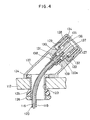
- Fig. 4 is a longitudinally sectional side elevation showing a temperature control knob 111
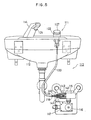
- Fig. 5 is a front elevation showing the whole structure of an automatic faucet device 113 installed on a lavatory sink 112.
- a spout body 114 and the temperature control knob 111 are mounted on the top surface of the lavatory sink 112.
- the aforementioned temperature control knob 111 is connected with the hot/cold water mixing faucet 115 through a push-pull cable 120 composed of an inner able 118 and an outer cable 119.
- a sensor (although not shown) for detecting the stretched hand of the user to turn on or off the electromagnetic valve 116 of the water stopper 117.
- the temperature control knob unit 111 has its knob body 122 disposed at an inclination on the mounting surface of the lavatory sink 112, as shown in Fig. 4. Moreover, this inclination is directed toward the user. As a result, the user can control the control knob 127 (as will be described hereinafter) of the knob body 122 while having his arm stretched but his wrist not bent so that the controls are excellent in the human engineering.
- the temperature control knob unit 111 is mounted by inserting the threaded cylinder of a base plate 124 into the mounting hole 123 of the lavatory sink 112 and by fastening a triangular packing 125 and a nut 126 from the lower side of the lavatory sink 112.
- the control knob 127 has a cylindrical liner member 128 screwed in its inner circumference, and the knob 127 and the liner member 128 are fastened by a double nut 129.
- the liner member 128 is formed with a flange 130 on the inner circumference of its lower end.
- an inner member 133 which is formed with a flange on the outer circumference of its upper end.
- the flange 130 of the aforementioned liner member 128 is engaged with the flange 132 of the inner member 133 so that it is prevented from coming out.
- the control knob 127 thus integrated with the liner member 128 can be turned at the upper end of the knob body 122.
- the outer cable 119 has its root 140 fixed to a faucet body 142 by a cap nut 141.
- the inner cable 118 has its leading end connected to a slider 144 for controlling the axial position of a temperature control valve 143.
- This turn of the control knob 127 is transmitted to the liner member 128 and the intermediate member 135 and further through the threaded portion 136 to the slider 137. Since this slider 137 is blocked against is turn by the hexagonal hole 133a, it is moved in the axial direction. In other words, the rotation of the control knob 127 is converted into the axial movement of the slider 137. As a result, the inner cable 118 is pushed or pulled. This motion of the inner cable 137 is transmitted to the slider 144 for controlling the axial position of the temperature control valve 143 of the hot/cold water mixing faucet 115. Therefore, the axial position of the temperature control valve 143 can be controlled to set and change the temperature of the hot water to be spouted.
- the hand is drawn from below the spout body 114. Then, this draw is detected by the sensor so that the electromagnetic valve 116 is turned off (or closed) to end the spout of the hot water.
- the present invention should not be limited to the embodiments thus far described but can be suitably modified.
- the present invention can be applied not only the automatic faucet device 113 but also an ordinary hot/cold water mixing faucet device to be installed on a table.
- the present invention can be used with not only the temperature control knob unit 111 but also a flow control knob of needle type.
- the faucet device of the present invention can joint or separate the control knob to and from the faucet body suitably in accordance with the various conditions of the place for its installation. This makes it unnecessary to manufacture the faucet device in the mode especially for the automatic faucet elaborately, apart from the modes to be used in a bath room, a kitchen or a lavatory. Moreover, the product control at the shop side can be facilitated. Since, still moreover, the control knob and the faucet body are assembled separately of each other, there can be attained another of the various excellent advantages that the complexity of structure and the complicatedness of assembly can be eliminated.
- the temperature and flow controls of the hot water to be spouted can be accomplished easily and accurately especially in case of the automatic faucet device.
- the position for mounting the faucet body is not restricted in connection with the controls and conveniences so that the faucet body can be mounted in a hidden state in the bath room, the kitchen and the lavatory to provide a neat appearance.
- the structure can be simplified to give the various excellent advantages including the facilitated production, the low production cost and the improved appearance.
- the knob body is mounted at an inclination on the surface of the lavatory sink, and this inclination is directed toward the user. This allows the user to grip and operate the control knob of the knob body while stretching his arm but not with the bent wrist. This operation is suited for the human engineering so that the knob mounting structure can be used with remarkable comfortableness.
Landscapes
- Engineering & Computer Science (AREA)
- Health & Medical Sciences (AREA)
- Life Sciences & Earth Sciences (AREA)
- Hydrology & Water Resources (AREA)
- Public Health (AREA)
- Water Supply & Treatment (AREA)
- Physics & Mathematics (AREA)
- General Physics & Mathematics (AREA)
- Automation & Control Theory (AREA)
- Domestic Plumbing Installations (AREA)
- Multiple-Way Valves (AREA)
- Mechanically-Actuated Valves (AREA)
Abstract
Applications Claiming Priority (7)
| Application Number | Priority Date | Filing Date | Title |
|---|---|---|---|
| JP20185089 | 1989-08-03 | ||
| JP201850/89 | 1989-08-03 | ||
| JP9470589U JPH0636381Y2 (ja) | 1989-08-10 | 1989-08-10 | 分離可能な湯水混合水栓 |
| JP94705/89U | 1989-08-10 | ||
| JP1989097044U JPH0336060U (fr) | 1989-08-18 | 1989-08-18 | |
| JP97044/89U | 1989-08-18 | ||
| PCT/JP1990/000961 WO1991002127A1 (fr) | 1989-08-03 | 1990-07-27 | Robinet melangeur pour eau chaude/froide et sa structure de fixation |
Publications (3)
| Publication Number | Publication Date |
|---|---|
| EP0436728A1 true EP0436728A1 (fr) | 1991-07-17 |
| EP0436728A4 EP0436728A4 (en) | 1992-07-01 |
| EP0436728B1 EP0436728B1 (fr) | 1995-02-22 |
Family
ID=27307618
Family Applications (1)
| Application Number | Title | Priority Date | Filing Date |
|---|---|---|---|
| EP90910889A Expired - Lifetime EP0436728B1 (fr) | 1989-08-03 | 1990-07-27 | Robinet melangeur pour eau chaude/froide et sa structure de fixation |
Country Status (6)
| Country | Link |
|---|---|
| US (1) | US5180140A (fr) |
| EP (1) | EP0436728B1 (fr) |
| KR (1) | KR940009374B1 (fr) |
| DE (1) | DE69017176T2 (fr) |
| ES (1) | ES2071106T3 (fr) |
| WO (1) | WO1991002127A1 (fr) |
Cited By (3)
| Publication number | Priority date | Publication date | Assignee | Title |
|---|---|---|---|---|
| FR2736070A1 (fr) * | 1995-06-28 | 1997-01-03 | Lacroix Jean Paul | Appareil sanitaire comportant un dispositif de manoeuvre manuelle pour actionner une cartouche de mitigeur |
| EP0852274A1 (fr) * | 1997-01-02 | 1998-07-08 | Allibert Sa. | Appareil sanitaire comportant un dispositif de manoeuvre manuelle pour actionner une cartouche de mitigeur |
| ITRE20100057A1 (it) * | 2010-07-06 | 2012-01-07 | River Spa | Miscelatore |
Families Citing this family (12)
| Publication number | Priority date | Publication date | Assignee | Title |
|---|---|---|---|---|
| DE19702038A1 (de) * | 1997-01-22 | 1998-07-23 | Grohe Kg Hans | Sanitärarmatur |
| CO5290317A1 (es) | 1999-07-02 | 2003-06-27 | Shell Int Research | Metodo de desplegar un sistema de transduccion de fluido accionado electricamente en un pozo |
| GB2403490B (en) * | 2003-07-04 | 2006-08-23 | Phil Head | Method of deploying and powering an electrically driven device in a well |
| FR2869124B1 (fr) * | 2004-04-19 | 2006-07-28 | Aby Zahreddine | Dispositif de regulation a distance du debit et de la temperature d'un liquide au sein d'un circuit de distribution |
| ES2323247T3 (es) * | 2005-09-20 | 2009-07-09 | Veritas Ag | Dispositivo de acoplamiento para la conexion de dispositivos conductores, preferentemente conector rapido. |
| DE102009001444A1 (de) * | 2009-03-10 | 2010-09-16 | Ceramtec Ag | Wasserarmatur |
| GB2494317A (en) | 2010-05-18 | 2013-03-06 | Artificial Lift Co Ltd | Mating unit enabling the deployment of a modular electrically driven device in a well |
| US8813839B2 (en) | 2011-03-04 | 2014-08-26 | Artificial Lift Company | Method of deploying and powering an electrically driven device in a well |
| DE202012101867U1 (de) | 2012-05-22 | 2012-08-29 | Aissa Zouhri | Entnahmepunktregelung eines Wasserentnahmepunkts |
| WO2016172037A2 (fr) * | 2015-04-24 | 2016-10-27 | Emerson Electric Co. | Unité de commande pour robinet d'appareils sous évier ayant une base de robinet sous évier et une tête de robinet au-dessus du robinet |
| GB201522999D0 (en) | 2015-12-27 | 2016-02-10 | Coreteq Ltd | The deployment of a modular electrically driven device in a well |
| CN113309187A (zh) * | 2021-06-08 | 2021-08-27 | 罗显女 | 水龙头的固定组件 |
Family Cites Families (13)
| Publication number | Priority date | Publication date | Assignee | Title |
|---|---|---|---|---|
| US2155233A (en) * | 1932-01-25 | 1939-04-18 | Milwaukee Gas Specialty Co | Control system |
| US3036777A (en) * | 1956-09-27 | 1962-05-29 | American Radiator & Standard | Adjustable thermal mixing valve |
| US3355964A (en) * | 1965-09-30 | 1967-12-05 | Ray H Pulliam | Tractor speed-of-shift regulating mechanism |
| CH478303A (de) * | 1967-07-12 | 1969-09-15 | Oederlin Cie Ag | Waschanordnung mit einem Waschtisch |
| IT950157B (it) * | 1972-03-14 | 1973-06-20 | Giacomini A | Gruppo idraulico di comando per vasca da bagno |
| EP0028444B1 (fr) * | 1979-10-31 | 1984-03-07 | AKERMAN & JEAVONS (BIRMINGHAM) LIMITED | Robinets mélangeurs |
| CH643621A5 (en) * | 1980-02-05 | 1984-06-15 | Geberit Ag | Fitting for the remote control of the discharge valve of a sink |
| US4325508A (en) * | 1980-04-02 | 1982-04-20 | Emerson Electric Co. | Thermostatic expansion valve with remote adjustment |
| JPS58152984A (ja) * | 1982-03-05 | 1983-09-10 | Tabuchi Seisakusho:Kk | サ−モスタツトミキシングバルブ |
| JPS6155485A (ja) * | 1984-08-28 | 1986-03-19 | Inax Corp | 自動温度調節式混合水栓 |
| FR2577254B1 (fr) * | 1985-02-08 | 1987-04-10 | Presto Robinets Sa | Perfectionnement aux dispositifs de fixation de robinets sur une paroi |
| JPH01224586A (ja) * | 1988-03-01 | 1989-09-07 | Takashi Mishina | 水道等出水、止水、水量の強弱を遠隔操作すること。 |
| JP2876605B2 (ja) * | 1988-11-25 | 1999-03-31 | 東陶機器株式会社 | ワンタッチ着脱式自動水栓 |
-
1990
- 1990-07-27 EP EP90910889A patent/EP0436728B1/fr not_active Expired - Lifetime
- 1990-07-27 ES ES90910889T patent/ES2071106T3/es not_active Expired - Lifetime
- 1990-07-27 WO PCT/JP1990/000961 patent/WO1991002127A1/fr not_active Ceased
- 1990-07-27 US US07/663,954 patent/US5180140A/en not_active Expired - Fee Related
- 1990-07-27 DE DE69017176T patent/DE69017176T2/de not_active Expired - Fee Related
- 1990-08-01 KR KR1019900011830A patent/KR940009374B1/ko not_active Expired - Fee Related
Cited By (3)
| Publication number | Priority date | Publication date | Assignee | Title |
|---|---|---|---|---|
| FR2736070A1 (fr) * | 1995-06-28 | 1997-01-03 | Lacroix Jean Paul | Appareil sanitaire comportant un dispositif de manoeuvre manuelle pour actionner une cartouche de mitigeur |
| EP0852274A1 (fr) * | 1997-01-02 | 1998-07-08 | Allibert Sa. | Appareil sanitaire comportant un dispositif de manoeuvre manuelle pour actionner une cartouche de mitigeur |
| ITRE20100057A1 (it) * | 2010-07-06 | 2012-01-07 | River Spa | Miscelatore |
Also Published As
| Publication number | Publication date |
|---|---|
| EP0436728A4 (en) | 1992-07-01 |
| KR940009374B1 (ko) | 1994-10-07 |
| EP0436728B1 (fr) | 1995-02-22 |
| ES2071106T3 (es) | 1995-06-16 |
| KR910004970A (ko) | 1991-03-29 |
| DE69017176T2 (de) | 1995-06-14 |
| US5180140A (en) | 1993-01-19 |
| WO1991002127A1 (fr) | 1991-02-21 |
| DE69017176D1 (de) | 1995-03-30 |
Similar Documents
| Publication | Publication Date | Title |
|---|---|---|
| EP0436728B1 (fr) | Robinet melangeur pour eau chaude/froide et sa structure de fixation | |
| US11959262B2 (en) | Electronic faucet with smart features | |
| CN100334305C (zh) | 拉出式水龙头 | |
| CN103975112B (zh) | 电子龙头 | |
| US4945943A (en) | Computerized water faucet | |
| US6438770B1 (en) | Electronically-controlled shower system | |
| US9715238B2 (en) | Electronic user interface for electronic mixing of water for residential faucets | |
| EP2013677B1 (fr) | Interface utilisateur pour vanne électronique mélangeur d'eau de robinet mitigeur domestique | |
| US4974636A (en) | Computerized water faucet | |
| EP0426639A1 (fr) | Mitigeur à levier unique | |
| EP3835914B1 (fr) | Robinets melangeurs a thermoregulateur | |
| EP2995728B1 (fr) | Dispositif et procédé d'alimentation en eau de type automatique sans contact | |
| JPH0636381Y2 (ja) | 分離可能な湯水混合水栓 | |
| JPH0749676B2 (ja) | 湯水混合水栓の離隔操作構造 | |
| IE904045A1 (en) | Improvements relating to taps | |
| US20250341081A1 (en) | Touchless faucet using hand tracking | |
| RU174451U1 (ru) | Устройство экономного потребления воды | |
| WO1993022714A1 (fr) | Dispositif de melange a vanne commandee electriquement | |
| JPH0640688Y2 (ja) | 水栓のハンドル取付構造 | |
| US20240410146A1 (en) | Sanitary Fitting and Sanitary Fitting System | |
| JP2002061250A (ja) | 手動開閉機能付き自動排水栓装置 | |
| JP2534204Y2 (ja) | 吐水装置 | |
| JPH077406Y2 (ja) | 水栓のハンドル取付構造 | |
| AU665102B2 (en) | Electrically controlled valve mixing device | |
| CA2990925A1 (fr) | Robinets fournissant un controle supplementaire de debit d'eau |
Legal Events
| Date | Code | Title | Description |
|---|---|---|---|
| PUAI | Public reference made under article 153(3) epc to a published international application that has entered the european phase |
Free format text: ORIGINAL CODE: 0009012 |
|
| 17P | Request for examination filed |
Effective date: 19910321 |
|
| AK | Designated contracting states |
Kind code of ref document: A1 Designated state(s): CH DE ES FR GB IT LI |
|
| A4 | Supplementary search report drawn up and despatched |
Effective date: 19920508 |
|
| AK | Designated contracting states |
Kind code of ref document: A4 Designated state(s): CH DE ES FR GB IT LI |
|
| 17Q | First examination report despatched |
Effective date: 19920903 |
|
| GRAA | (expected) grant |
Free format text: ORIGINAL CODE: 0009210 |
|
| AK | Designated contracting states |
Kind code of ref document: B1 Designated state(s): CH DE ES FR GB IT LI |
|
| REF | Corresponds to: |
Ref document number: 69017176 Country of ref document: DE Date of ref document: 19950330 |
|
| ITF | It: translation for a ep patent filed | ||
| ET | Fr: translation filed | ||
| REG | Reference to a national code |
Ref country code: ES Ref legal event code: FG2A Ref document number: 2071106 Country of ref document: ES Kind code of ref document: T3 |
|
| PLBE | No opposition filed within time limit |
Free format text: ORIGINAL CODE: 0009261 |
|
| STAA | Information on the status of an ep patent application or granted ep patent |
Free format text: STATUS: NO OPPOSITION FILED WITHIN TIME LIMIT |
|
| 26N | No opposition filed | ||
| PGFP | Annual fee paid to national office [announced via postgrant information from national office to epo] |
Ref country code: GB Payment date: 19980630 Year of fee payment: 9 |
|
| PGFP | Annual fee paid to national office [announced via postgrant information from national office to epo] |
Ref country code: FR Payment date: 19980717 Year of fee payment: 9 Ref country code: ES Payment date: 19980717 Year of fee payment: 9 |
|
| PGFP | Annual fee paid to national office [announced via postgrant information from national office to epo] |
Ref country code: CH Payment date: 19980818 Year of fee payment: 9 |
|
| PGFP | Annual fee paid to national office [announced via postgrant information from national office to epo] |
Ref country code: DE Payment date: 19980827 Year of fee payment: 9 |
|
| PG25 | Lapsed in a contracting state [announced via postgrant information from national office to epo] |
Ref country code: GB Free format text: LAPSE BECAUSE OF NON-PAYMENT OF DUE FEES Effective date: 19990727 |
|
| PG25 | Lapsed in a contracting state [announced via postgrant information from national office to epo] |
Ref country code: ES Free format text: LAPSE BECAUSE OF NON-PAYMENT OF DUE FEES Effective date: 19990728 |
|
| PG25 | Lapsed in a contracting state [announced via postgrant information from national office to epo] |
Ref country code: LI Free format text: LAPSE BECAUSE OF NON-PAYMENT OF DUE FEES Effective date: 19990731 Ref country code: FR Free format text: THE PATENT HAS BEEN ANNULLED BY A DECISION OF A NATIONAL AUTHORITY Effective date: 19990731 Ref country code: CH Free format text: LAPSE BECAUSE OF NON-PAYMENT OF DUE FEES Effective date: 19990731 |
|
| GBPC | Gb: european patent ceased through non-payment of renewal fee |
Effective date: 19990727 |
|
| REG | Reference to a national code |
Ref country code: CH Ref legal event code: PL |
|
| PG25 | Lapsed in a contracting state [announced via postgrant information from national office to epo] |
Ref country code: DE Free format text: LAPSE BECAUSE OF NON-PAYMENT OF DUE FEES Effective date: 20000503 |
|
| REG | Reference to a national code |
Ref country code: FR Ref legal event code: ST |
|
| REG | Reference to a national code |
Ref country code: ES Ref legal event code: FD2A Effective date: 20000810 |
|
| PG25 | Lapsed in a contracting state [announced via postgrant information from national office to epo] |
Ref country code: IT Free format text: LAPSE BECAUSE OF NON-PAYMENT OF DUE FEES;WARNING: LAPSES OF ITALIAN PATENTS WITH EFFECTIVE DATE BEFORE 2007 MAY HAVE OCCURRED AT ANY TIME BEFORE 2007. THE CORRECT EFFECTIVE DATE MAY BE DIFFERENT FROM THE ONE RECORDED. Effective date: 20050727 |