EP0436792A2 - Presse pour fabriquer des articles pressés en matière pulvérulente à dimensions exactes - Google Patents
Presse pour fabriquer des articles pressés en matière pulvérulente à dimensions exactes Download PDFInfo
- Publication number
- EP0436792A2 EP0436792A2 EP90121145A EP90121145A EP0436792A2 EP 0436792 A2 EP0436792 A2 EP 0436792A2 EP 90121145 A EP90121145 A EP 90121145A EP 90121145 A EP90121145 A EP 90121145A EP 0436792 A2 EP0436792 A2 EP 0436792A2
- Authority
- EP
- European Patent Office
- Prior art keywords
- pots
- press
- pot
- base plate
- press according
- Prior art date
- Legal status (The legal status is an assumption and is not a legal conclusion. Google has not performed a legal analysis and makes no representation as to the accuracy of the status listed.)
- Granted
Links
Images

Classifications
-
- B—PERFORMING OPERATIONS; TRANSPORTING
- B30—PRESSES
- B30B—PRESSES IN GENERAL
- B30B11/00—Presses specially adapted for forming shaped articles from material in particulate or plastic state, e.g. briquetting presses, tabletting presses
- B30B11/02—Presses specially adapted for forming shaped articles from material in particulate or plastic state, e.g. briquetting presses, tabletting presses using a ram exerting pressure on the material in a moulding space
Definitions
- the invention relates to a press for producing dimensionally stable, in particular stepped, compacts according to the preamble of patent claim 1.
- the stamp carriers can be moved hydraulically into the filling position and into the press end position, the stamp carriers in the press end position being supported against the base plate by means of fixed stops in the form of sleeves, so that the pressing forces on the stamp carrier into the base plate and from there into the Press removed or recorded there.
- the stamp carriers are designed as stamp carrier plates with a square plan. Two diametrically opposed piston / cylinder units actuate one of the stamp carrier plates in which the tool stamps are received. Since the stamp carrier plates are not rigidly connected to the framework, they have four openings at the corners, which are equipped with guide sleeves and are provided for the passage of the tie rods or the displaceable mounting of the receiving plates relative to the framework.
- the object of the invention is to provide a press for the production of dimensionally stable, in particular stepped compacts, which, with a simple and robust construction, ensures a jam-free guidance of the stamp carrier and good power transmission in the press end position. Furthermore, the dimension of the tool frame should also be reduced, in particular in the axial direction. In addition, a tilt-proof construction and an improved absorption of eccentric forces is sought.
- the stamp carriers for receiving the tool stamps are no longer realized as receiving plates which are displaceably guided on the framework, but rather are designed as pots which are guided on cylindrical surfaces relative to the base plate.
- This design results in considerable advantages over the conventional tool frame, because the four guides in the corners of the mounting plates, which are necessary for the displacement of the mounting plates relative to the framework, are omitted, which have to be exactly coordinated.
- the guide on the tie rods is omitted in favor of a guide relative to the base plate or relative to the base plate via a guide provided on the pot, in particular via the cylindrical outer or inner surface of the pot.
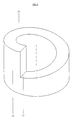
- the pots rest with their lower axial end faces on setting rings, the bearing surface of both parts, that is to say setting ring and pot, being designed in the manner of a catchy screw surface.
- setting rings the bearing surface of both parts, that is to say setting ring and pot, being designed in the manner of a catchy screw surface.
- Such presses are designed for pressing forces of up to approximately 800 t. Due to the setting rings, there is a much larger area available for power transmission than conventional caps. The setting rings only have to be designed taking into account the adjustment stroke to be achieved for the pots. Due to the screw surface are in any rotational position of the setting ring compared to the pot between 100 and 75% of the area available for power transmission.
- the design of the stamp carrier in the manner of pots at the upper connecting piece can be carried out in isolation from the design of the tool frame determined via the framework and thus independently of the stamp carriers assigned to the base plate.
- the design of the stamp carrier in the region of the upper connecting piece is implemented in the manner of pots in connection with the formation of the stamp carrier of the base plate in the manner of pots, which overall results in a very stable, space-saving and robust construction of a tool frame.
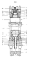
- the tool frame explained with reference to FIGS. 1 to 4 comprises a base plate designated by 1, which is firmly connected and supported with the press after the installation of the tool frame designated by 2.
- a framework is slidably guided, which is constructed from a lower coupling plate 3 and a die holding plate 4, which are rigidly connected to one another via tie rods 5.
- the framework is part of the tool frame 2.
- the displaceable guidance of the framework in the base plate 1 takes place via tie rods 5, four of which are provided in the exemplary embodiment shown in accordance with FIG. 3.
- the lower clutch plate 3 is coupled or connected to the lower press bear of the press.
- the tool frame is connected to the upper press bear via an upper connecting piece designated 6, which is guided relative to the die holding plate 4.
- an upper connecting piece designated 6 which is guided relative to the die holding plate 4.
- four guide rods 7 are provided with the upper connecting piece 6 in the illustrated embodiment, which are guided in corresponding openings in the die holding plate 4.
- the guide rods 7 can also be firmly connected to the die holding plate 4, so that the upper connecting piece 6 is displaceable relative to the guide rods 7.
- stamp carriers 8, 9 and 10 are moved hydraulically from the base plate 1.
- the stamp carriers 8, 9 and 10 serve to hold the actual tool stamp. It is important here that the stamp carriers 8 to 10 are no longer formed in the manner of stamp carrier plates which are guided on the four tie rods 5, but in the manner of pots which are guided on their cylindrical surfaces relative to the base plate 1, as in detail is explained.
- the movement of the radially inner central pot 8 takes place via a piston 11, which is received with an annular shoulder 12 in a chamber 14, which represents the cylinder of the piston / cylinder unit, in the base plate 1.
- the pot 8 is fastened to the piston 11, slightly screwed, and the piston 11 is guided in bushes 15 and 15 'received by the base plate 1.
- the pot 9 is in turn guided at 16 on the inner surface of a sleeve 17 which is fixedly arranged on the plate 1.
- the pot 10 with its cylindrical inner surface is guided at 18 on the cylindrical outer surface.
- the guide surfaces can be formed by guide bushes made of a material with particularly good sliding properties. These guide bushes or coatings are shown in the drawing. Analogously to the guide bushing 19 of the pot 10, they can be designed on the pot itself or on the counter surface.
- the sealing elements are designated 20.
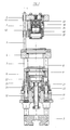
- the movement of the pot 9 takes place via two piston / cylinder units 13 shown in FIG. 2, which are received at one end in the base plate 1 and act at the other end on the underside of the pot 9, in particular on radially projecting eyes 21 the pot 9, as best seen in FIG. 3.
- Two piston / cylinder units are used to move the pot 9, which are arranged diametrically opposite one another according to FIG. 2.
- FIG. 3 shows quite clearly, the radial distance between the piston / cylinder units for the pot 9 and for the pot 10 is the same relative to the axis of the tool frame.
- pots 8 to 10 are supported on fixed stops relative to the base plate 1.
- these fixed stops are formed by adjusting rings 23, 24 and 25.
- the pots 8 to 10 lie with their lower axial end faces on the upper end faces of the adjusting rings 23 to 25 in the press end position.
- the support surface 26 for the associated pot is designed as a screw surface-like ramp, in the manner of a single-thread screw surface, the thread ends of the screw surface (one thread) being connected at 27 by a vertical connecting surface are.
- the corresponding axial lower end face of each pot 8 to 10 is complementary to the screw surface 26.
- an adjusting ring for example of the adjusting ring 23, has the consequence that, depending on the direction of rotation, the associated pot, here the pot 8, is raised or lowered. As a result, the press end position can be changed or adjusted via the stroke of the pot.
- the rotary movement of the adjusting ring takes place in each case via an outwardly guided screw spindle, the screw spindles 28 and 29, which are assigned to the pots 8 and 10, being apparent from FIG. 1.
- Fig. 3 shows schematically the screw spindles 29 and 30 which are assigned to the pots 10 and 9.
- the adjusting rings are designed with regard to the pitch of the screw surface 26 so that a stroke adjustment of up to 20 mm would be possible, since, however, in the preferred embodiment only an adjusting height of about 5 mm is required, so each adjusting ring only has to be rotated through 90 ° a limitation of the rotational movement is provided.
- a pin 31 arranged in the setting ring 23 is used for this purpose, which engages in a groove 32 on the end face of the base plate 1, which extends over an angle of 90 °.
- Analog limits can be provided for the other setting rings.
- stamp carriers in the form of pots 34 and 35 are also arranged on the upper connection piece, which are moved hydraulically by the upper connection piece 6.
- a centrally arranged stamp carrier 33 is actuated via a piston / cylinder unit 36 accommodated in the upper connection piece 6, the piston of which is guided in two bushings received by the connection piece 6, one of which is designated by 43.
- the pot 34 is guided with its cylindrical inner surface on the cylindrical outer surface of the bush 43 and is actuated by two piston / cylinder units which act on eyes protruding radially outwards analogously to the pot 9 and are also arranged diametrically opposite. These piston / cylinder units are shown in FIG. 2.
- the pot 35 is also actuated by two piston / cylinder units 37 shown in FIG. 1, which are arranged diametrically opposite one another.
- a sleeve 38 which is fixedly connected to the upper connecting piece 6 and in which the annular piston 39 of the piston / cylinder unit 37 is guided, is used to guide the pot 34.
- the pot 35 is guided on the inner surface of a sleeve-like end part 40 which is firmly connected to the sleeve 38.
- the pots 34 and 35 are via setting rings 41 and 42 adjustable, whereby reference can be made to the description of the lower pots.
- the operation of the press is as follows: For filling, the punch carriers are moved upwards or downwards from the base plate 1 or from the upper connecting piece 6 in the direction of the die holding plate 4. After filling the resulting mold with powder made of ceramic material, the press stroke is carried out by moving the upper and lower press bears together, causing the pots 8 to 10 and 31 to 33 to reach their final press position, in which they are positioned against the by means of fixed stops, i.e. the setting rings Base plate 1 and the upper connector 6 are supported. This ensures good power transmission via the interacting surfaces of the pots and adjusting rings.
Landscapes
- Engineering & Computer Science (AREA)
- Mechanical Engineering (AREA)
- Press Drives And Press Lines (AREA)
- Mounting, Exchange, And Manufacturing Of Dies (AREA)
- Battery Electrode And Active Subsutance (AREA)
- Press-Shaping Or Shaping Using Conveyers (AREA)
Applications Claiming Priority (2)
| Application Number | Priority Date | Filing Date | Title |
|---|---|---|---|
| DE4000423A DE4000423C2 (de) | 1990-01-09 | 1990-01-09 | Presse zur Herstellung maßhaltiger Preßlinge aus pulverförmigem Material |
| DE4000423 | 1990-01-09 |
Publications (3)
| Publication Number | Publication Date |
|---|---|
| EP0436792A2 true EP0436792A2 (fr) | 1991-07-17 |
| EP0436792A3 EP0436792A3 (en) | 1991-09-18 |
| EP0436792B1 EP0436792B1 (fr) | 1994-05-25 |
Family
ID=6397774
Family Applications (1)
| Application Number | Title | Priority Date | Filing Date |
|---|---|---|---|
| EP90121145A Expired - Lifetime EP0436792B1 (fr) | 1990-01-09 | 1990-11-05 | Presse pour fabriquer des articles pressés en matière pulvérulente à dimensions exactes |
Country Status (4)
| Country | Link |
|---|---|
| EP (1) | EP0436792B1 (fr) |
| JP (1) | JP2941070B2 (fr) |
| AT (1) | ATE106040T1 (fr) |
| DE (1) | DE4000423C2 (fr) |
Cited By (9)
| Publication number | Priority date | Publication date | Assignee | Title |
|---|---|---|---|---|
| EP0561159A1 (fr) * | 1992-03-17 | 1993-09-22 | KOMAGE GELLNER MASCHINENFABRIK GmbH | Dispositif pour la pressage de corps moulés à partir d'une matière à grains fins |
| US6902698B2 (en) | 2001-07-20 | 2005-06-07 | Dorst Technologies Gmbh & Co. Kg. | Press apparatus for producing dimensionally accurate pressed articles from a powdered material |
| US7229263B2 (en) | 2002-11-22 | 2007-06-12 | Dorst Technologies Gmbh & Co. Kg | Pressing device for manufacturing of shaped compacts from pulverized material |
| CN102744320A (zh) * | 2011-04-21 | 2012-10-24 | 中国北车集团大同电力机车有限责任公司 | 冲压模具 |
| WO2012126462A3 (fr) * | 2011-03-24 | 2013-01-03 | Sms Meer Gmbh | Presse pour produire une pièce moulée et procédé pour changer une matrice sur une presse |
| CN104338852A (zh) * | 2013-08-09 | 2015-02-11 | 睿励科学仪器(上海)有限公司 | 一种模具 |
| EP3530446A1 (fr) * | 2018-02-26 | 2019-08-28 | Osterwalder AG | Presse à poudre dotée de levier à genouillère et d'entraînement électrique |
| EP3530445A1 (fr) * | 2018-02-26 | 2019-08-28 | Osterwalder AG | Presse à poudre à entraînement à levier à genouillère |
| EP3530448A1 (fr) * | 2018-02-26 | 2019-08-28 | Osterwalder AG | Dispositif de presse pour une presse à poudre et un système de changement d'outil |
Families Citing this family (4)
| Publication number | Priority date | Publication date | Assignee | Title |
|---|---|---|---|---|
| DE4227640A1 (de) * | 1992-08-18 | 1994-02-24 | Mannesmann Ag | Presse zur Herstellung maßhaltiger Preßkörper |
| JP4766031B2 (ja) | 2007-10-23 | 2011-09-07 | トヨタ自動車株式会社 | 倒立型移動体および倒立型移動体の制御方法 |
| JP4702414B2 (ja) | 2008-07-29 | 2011-06-15 | トヨタ自動車株式会社 | 同軸二輪車及び同軸二輪車の制御方法 |
| JP4798181B2 (ja) | 2008-07-29 | 2011-10-19 | トヨタ自動車株式会社 | 移動体、走行装置、移動体の制御方法 |
Family Cites Families (7)
| Publication number | Priority date | Publication date | Assignee | Title |
|---|---|---|---|---|
| US2556951A (en) * | 1944-06-05 | 1951-06-12 | Stokes Machine Co | Powdered material compacting press |
| GB677234A (en) * | 1947-10-20 | 1952-08-13 | Haller John | An improved machine for briquetting powdered metal |
| US2810929A (en) * | 1953-05-06 | 1957-10-29 | Baldwin Lima Hamilton Corp | Apparatus for compacting and ejecting flanged articles |
| US3353215A (en) * | 1965-11-10 | 1967-11-21 | Haller John | Powdered material briquetting press |
| US3593366A (en) * | 1968-12-11 | 1971-07-20 | Wolverine Pentronix | Multiple punch tool set for powder compacting press |
| FR2052127A5 (fr) * | 1969-07-18 | 1971-04-09 | Basset Jacques | |
| DE3142126A1 (de) * | 1981-10-23 | 1983-05-11 | Dorst-Keramikmaschinen-Bau Otto Dorst U. Dipl.-Ing. Walter Schlegel, 8113 Kochel | "presse zum herstellen masshaltiger presslinge aus pulverfoermigem material" |
-
1990
- 1990-01-09 DE DE4000423A patent/DE4000423C2/de not_active Expired - Lifetime
- 1990-11-05 AT AT90121145T patent/ATE106040T1/de not_active IP Right Cessation
- 1990-11-05 EP EP90121145A patent/EP0436792B1/fr not_active Expired - Lifetime
-
1991
- 1991-01-08 JP JP3000428A patent/JP2941070B2/ja not_active Expired - Fee Related
Cited By (19)
| Publication number | Priority date | Publication date | Assignee | Title |
|---|---|---|---|---|
| EP0561159A1 (fr) * | 1992-03-17 | 1993-09-22 | KOMAGE GELLNER MASCHINENFABRIK GmbH | Dispositif pour la pressage de corps moulés à partir d'une matière à grains fins |
| US6902698B2 (en) | 2001-07-20 | 2005-06-07 | Dorst Technologies Gmbh & Co. Kg. | Press apparatus for producing dimensionally accurate pressed articles from a powdered material |
| US7229263B2 (en) | 2002-11-22 | 2007-06-12 | Dorst Technologies Gmbh & Co. Kg | Pressing device for manufacturing of shaped compacts from pulverized material |
| US9724846B2 (en) | 2011-03-24 | 2017-08-08 | Sms Group Gmbh | Press for producing a molded part and method for changing a die on a press |
| WO2012126462A3 (fr) * | 2011-03-24 | 2013-01-03 | Sms Meer Gmbh | Presse pour produire une pièce moulée et procédé pour changer une matrice sur une presse |
| US10647027B2 (en) | 2011-03-24 | 2020-05-12 | Sms Group Gmbh | Press for production of a molded part and method for changing a die on a press |
| CN102744320B (zh) * | 2011-04-21 | 2014-11-19 | 中国北车集团大同电力机车有限责任公司 | 冲压模具 |
| CN102744320A (zh) * | 2011-04-21 | 2012-10-24 | 中国北车集团大同电力机车有限责任公司 | 冲压模具 |
| CN104338852A (zh) * | 2013-08-09 | 2015-02-11 | 睿励科学仪器(上海)有限公司 | 一种模具 |
| CN104338852B (zh) * | 2013-08-09 | 2016-05-25 | 睿励科学仪器(上海)有限公司 | 一种模具 |
| EP3530445A1 (fr) * | 2018-02-26 | 2019-08-28 | Osterwalder AG | Presse à poudre à entraînement à levier à genouillère |
| EP3530448A1 (fr) * | 2018-02-26 | 2019-08-28 | Osterwalder AG | Dispositif de presse pour une presse à poudre et un système de changement d'outil |
| WO2019162510A1 (fr) * | 2018-02-26 | 2019-08-29 | Osterwalder Ag | Dispositif de pressage pour presse à poudre et système de changement d'outil |
| WO2019162511A1 (fr) * | 2018-02-26 | 2019-08-29 | Osterwalder Ag | Presse à poudre à entrainement à genouillère et à entrainement électrique |
| EP3530446A1 (fr) * | 2018-02-26 | 2019-08-28 | Osterwalder AG | Presse à poudre dotée de levier à genouillère et d'entraînement électrique |
| CN111770831A (zh) * | 2018-02-26 | 2020-10-13 | 奥斯瓦尔德股份公司 | 具有肘杆驱动器和电驱动器的粉末压机 |
| CN111819072A (zh) * | 2018-02-26 | 2020-10-23 | 奥斯瓦尔德股份公司 | 用于粉末压机的压制设备以及工具更换系统 |
| US11820094B2 (en) | 2018-02-26 | 2023-11-21 | Osterwalder Ag | Powder press having toggle lever drive and electric drive |
| US12097679B2 (en) | 2018-02-26 | 2024-09-24 | Osterwalder Ag | Press device for a powder press and a tool changing system |
Also Published As
| Publication number | Publication date |
|---|---|
| ATE106040T1 (de) | 1994-06-15 |
| JP2941070B2 (ja) | 1999-08-25 |
| EP0436792A3 (en) | 1991-09-18 |
| EP0436792B1 (fr) | 1994-05-25 |
| JPH04162995A (ja) | 1992-06-08 |
| DE4000423C2 (de) | 1998-10-08 |
| DE4000423A1 (de) | 1991-07-11 |
Similar Documents
| Publication | Publication Date | Title |
|---|---|---|
| AT505947B1 (de) | Verdichtungswerkzeug | |
| EP0108935B1 (fr) | Presse à estamper à poinçon multiple | |
| DE3110221C2 (de) | Revolverstanzpresse | |
| EP0436792B1 (fr) | Presse pour fabriquer des articles pressés en matière pulvérulente à dimensions exactes | |
| DE29713253U1 (de) | Überlastkupplung | |
| DE2801225A1 (de) | Presswerkzeug zum pressen eines pulverfoermigen materials in ein geformtes werkstueck | |
| EP1422050B1 (fr) | Dispositif pour fabriquer des articles pressés conservant leur dimension à partir de matières pulvérulentes | |
| EP2387542B1 (fr) | Tête de bouchage pour machine à boucher des récipients et machine à boucher des récipients correspondante | |
| EP1743724B1 (fr) | Methode de production d'une liaison de forme pour fixer un element d'outil amovible à son support dans un outil rotatif | |
| DE1948119B2 (de) | Teileinrichtung an einer maschine zum abschraegen von stirnkanten an kegelritzeln | |
| EP2036710B1 (fr) | Rotor pour presse rotative pour comprimés | |
| EP1764173B1 (fr) | Dispositif pour mouler de la poudre par pression | |
| DE2437753B2 (de) | Hubverstellbarer, doppeltwirkender Kolbenmotor | |
| EP3075505B1 (fr) | Dispositif de fabrication d'éléments de formage en béton | |
| DE3342948C2 (fr) | ||
| DE69515075T2 (de) | Verfahren zur Herstellung einer Mehrfachriemenscheibe, Formwerkzeug zur Durchführung des Verfahrens und so hergestellte Riemenscheibe | |
| DE10061403B4 (de) | Verfahren zur Herstellung eines rotationssymmetrischen Formkörpers | |
| EP4279257B1 (fr) | Outil de pastillage | |
| DE3432939C2 (fr) | ||
| DE10158861A1 (de) | Vorrichtung zum Bewegen eines Stößels einer Presse | |
| DE4032106A1 (de) | Hydraulische presse | |
| AT379986B (de) | Mechanische presse mit untertischantrieb | |
| DE2644680C3 (de) | Einrichtung an einer Presse für die Verformung zylindrischer Rohlinge | |
| DE1527753C3 (de) | Walzgerüst mit wahlweise zwei oder mehr Walzen | |
| DE102005027032A1 (de) | Vorrichtung zum Herstellen eines Formteils |
Legal Events
| Date | Code | Title | Description |
|---|---|---|---|
| PUAI | Public reference made under article 153(3) epc to a published international application that has entered the european phase |
Free format text: ORIGINAL CODE: 0009012 |
|
| AK | Designated contracting states |
Kind code of ref document: A2 Designated state(s): AT CH FR GB IT LI SE |
|
| PUAL | Search report despatched |
Free format text: ORIGINAL CODE: 0009013 |
|
| AK | Designated contracting states |
Kind code of ref document: A3 Designated state(s): AT CH FR GB IT LI SE |
|
| 17P | Request for examination filed |
Effective date: 19920318 |
|
| 17Q | First examination report despatched |
Effective date: 19930630 |
|
| GRAA | (expected) grant |
Free format text: ORIGINAL CODE: 0009210 |
|
| AK | Designated contracting states |
Kind code of ref document: B1 Designated state(s): AT CH FR GB IT LI SE |
|
| PG25 | Lapsed in a contracting state [announced via postgrant information from national office to epo] |
Ref country code: SE Free format text: THE PATENT HAS BEEN ANNULLED BY A DECISION OF A NATIONAL AUTHORITY Effective date: 19940525 |
|
| REF | Corresponds to: |
Ref document number: 106040 Country of ref document: AT Date of ref document: 19940615 Kind code of ref document: T |
|
| GBT | Gb: translation of ep patent filed (gb section 77(6)(a)/1977) |
Effective date: 19940606 |
|
| ET | Fr: translation filed | ||
| ITF | It: translation for a ep patent filed | ||
| PG25 | Lapsed in a contracting state [announced via postgrant information from national office to epo] |
Ref country code: AT Effective date: 19941105 |
|
| PLBE | No opposition filed within time limit |
Free format text: ORIGINAL CODE: 0009261 |
|
| STAA | Information on the status of an ep patent application or granted ep patent |
Free format text: STATUS: NO OPPOSITION FILED WITHIN TIME LIMIT |
|
| 26N | No opposition filed | ||
| REG | Reference to a national code |
Ref country code: GB Ref legal event code: IF02 |
|
| REG | Reference to a national code |
Ref country code: CH Ref legal event code: PFA Owner name: DORST TECHNOLOGIES GMBH & CO. KG Free format text: DORST MASCHINEN UND ANLAGENBAU OTTO DORST UND DIPL.-ING. WALTER SCHLEGEL GMBH & CO.#MITTENWALDERSTRASSE 61 P.O. BOX 109 + 129#KOCHEL AM SEE (DE) -TRANSFER TO- DORST TECHNOLOGIES GMBH & CO. KG#MITTENWALDERSTRASSE 61 P.O. BOX 109 + 129#KOCHEL AM SEE (DE) Ref country code: CH Ref legal event code: NV Representative=s name: TROESCH SCHEIDEGGER WERNER AG Ref country code: GB Ref legal event code: 732E |
|
| REG | Reference to a national code |
Ref country code: FR Ref legal event code: CD |
|
| PGFP | Annual fee paid to national office [announced via postgrant information from national office to epo] |
Ref country code: GB Payment date: 20071123 Year of fee payment: 18 |
|
| PGFP | Annual fee paid to national office [announced via postgrant information from national office to epo] |
Ref country code: FR Payment date: 20081118 Year of fee payment: 19 |
|
| GBPC | Gb: european patent ceased through non-payment of renewal fee |
Effective date: 20081105 |
|
| PG25 | Lapsed in a contracting state [announced via postgrant information from national office to epo] |
Ref country code: GB Free format text: LAPSE BECAUSE OF NON-PAYMENT OF DUE FEES Effective date: 20081105 |
|
| PGFP | Annual fee paid to national office [announced via postgrant information from national office to epo] |
Ref country code: CH Payment date: 20091124 Year of fee payment: 20 |
|
| PGFP | Annual fee paid to national office [announced via postgrant information from national office to epo] |
Ref country code: IT Payment date: 20091128 Year of fee payment: 20 |
|
| REG | Reference to a national code |
Ref country code: FR Ref legal event code: ST Effective date: 20100730 |
|
| PG25 | Lapsed in a contracting state [announced via postgrant information from national office to epo] |
Ref country code: FR Free format text: LAPSE BECAUSE OF NON-PAYMENT OF DUE FEES Effective date: 20091130 |
|
| REG | Reference to a national code |
Ref country code: CH Ref legal event code: PL |