EP3530446A1 - Presse à poudre dotée de levier à genouillère et d'entraînement électrique - Google Patents
Presse à poudre dotée de levier à genouillère et d'entraînement électrique Download PDFInfo
- Publication number
- EP3530446A1 EP3530446A1 EP18158665.2A EP18158665A EP3530446A1 EP 3530446 A1 EP3530446 A1 EP 3530446A1 EP 18158665 A EP18158665 A EP 18158665A EP 3530446 A1 EP3530446 A1 EP 3530446A1
- Authority
- EP
- European Patent Office
- Prior art keywords
- press
- drive
- punch
- powder press
- powder
- Prior art date
- Legal status (The legal status is an assumption and is not a legal conclusion. Google has not performed a legal analysis and makes no representation as to the accuracy of the status listed.)
- Granted
Links
Images



Classifications
-
- B—PERFORMING OPERATIONS; TRANSPORTING
- B30—PRESSES
- B30B—PRESSES IN GENERAL
- B30B1/00—Presses, using a press ram, characterised by the features of the drive therefor, pressure being transmitted directly, or through simple thrust or tension members only, to the press ram or platen
- B30B1/10—Presses, using a press ram, characterised by the features of the drive therefor, pressure being transmitted directly, or through simple thrust or tension members only, to the press ram or platen by toggle mechanism
- B30B1/103—Presses, using a press ram, characterised by the features of the drive therefor, pressure being transmitted directly, or through simple thrust or tension members only, to the press ram or platen by toggle mechanism operated by screw means
-
- B—PERFORMING OPERATIONS; TRANSPORTING
- B22—CASTING; POWDER METALLURGY
- B22F—WORKING METALLIC POWDER; MANUFACTURE OF ARTICLES FROM METALLIC POWDER; MAKING METALLIC POWDER; APPARATUS OR DEVICES SPECIALLY ADAPTED FOR METALLIC POWDER
- B22F3/00—Manufacture of workpieces or articles from metallic powder characterised by the manner of compacting or sintering; Apparatus specially adapted therefor ; Presses and furnaces
- B22F3/02—Compacting only
- B22F3/03—Press-moulding apparatus therefor
-
- B—PERFORMING OPERATIONS; TRANSPORTING
- B30—PRESSES
- B30B—PRESSES IN GENERAL
- B30B11/00—Presses specially adapted for forming shaped articles from material in particulate or plastic state, e.g. briquetting presses, tabletting presses
- B30B11/02—Presses specially adapted for forming shaped articles from material in particulate or plastic state, e.g. briquetting presses, tabletting presses using a ram exerting pressure on the material in a moulding space
-
- B—PERFORMING OPERATIONS; TRANSPORTING
- B30—PRESSES
- B30B—PRESSES IN GENERAL
- B30B15/00—Details of, or accessories for, presses; Auxiliary measures in connection with pressing
- B30B15/0029—Details of, or accessories for, presses; Auxiliary measures in connection with pressing means for adjusting the space between the press slide and the press table, i.e. the shut height
-
- B—PERFORMING OPERATIONS; TRANSPORTING
- B22—CASTING; POWDER METALLURGY
- B22F—WORKING METALLIC POWDER; MANUFACTURE OF ARTICLES FROM METALLIC POWDER; MAKING METALLIC POWDER; APPARATUS OR DEVICES SPECIALLY ADAPTED FOR METALLIC POWDER
- B22F3/00—Manufacture of workpieces or articles from metallic powder characterised by the manner of compacting or sintering; Apparatus specially adapted therefor ; Presses and furnaces
- B22F3/02—Compacting only
- B22F3/03—Press-moulding apparatus therefor
- B22F2003/033—Press-moulding apparatus therefor with multiple punches working in the same direction
-
- B—PERFORMING OPERATIONS; TRANSPORTING
- B22—CASTING; POWDER METALLURGY
- B22F—WORKING METALLIC POWDER; MANUFACTURE OF ARTICLES FROM METALLIC POWDER; MAKING METALLIC POWDER; APPARATUS OR DEVICES SPECIALLY ADAPTED FOR METALLIC POWDER
- B22F2999/00—Aspects linked to processes or compositions used in powder metallurgy
-
- B—PERFORMING OPERATIONS; TRANSPORTING
- B29—WORKING OF PLASTICS; WORKING OF SUBSTANCES IN A PLASTIC STATE IN GENERAL
- B29C—SHAPING OR JOINING OF PLASTICS; SHAPING OF MATERIAL IN A PLASTIC STATE, NOT OTHERWISE PROVIDED FOR; AFTER-TREATMENT OF THE SHAPED PRODUCTS, e.g. REPAIRING
- B29C45/00—Injection moulding, i.e. forcing the required volume of moulding material through a nozzle into a closed mould; Apparatus therefor
- B29C45/17—Component parts, details or accessories; Auxiliary operations
- B29C45/64—Mould opening, closing or clamping devices
- B29C45/66—Mould opening, closing or clamping devices mechanical
-
- B—PERFORMING OPERATIONS; TRANSPORTING
- B30—PRESSES
- B30B—PRESSES IN GENERAL
- B30B1/00—Presses, using a press ram, characterised by the features of the drive therefor, pressure being transmitted directly, or through simple thrust or tension members only, to the press ram or platen
- B30B1/18—Presses, using a press ram, characterised by the features of the drive therefor, pressure being transmitted directly, or through simple thrust or tension members only, to the press ram or platen by screw means
- B30B1/186—Control arrangements
Definitions
- the invention relates to a powder press for producing a compact of a compressible material.
- presses in particular powder presses, have a press frame, upper and lower punch assemblies, and a die assembly between the two punch assemblies.
- the punch arrangements and the die arrangement define a mold cavity in which the material to be pressed, in particular pulverulent material, is introduced.
- upper and lower punch arrangements comprising at least one tool plane with a tool or at least one punch, are pressed against one another, wherein the movement of the punch arrangements takes place as a function of adjustable pressing parameters.
- a stamp assembly in the simplest case comprises a stamp, but generally has a plurality of punches.
- Arrangements with a plurality of punches are also known in order to press several height stages in the pressing direction, wherein the individual punches are moved relative to one another at different speeds and / or stroke distances and are accommodated in a tool level.
- the punch arrangements In a final press position in which a full pressing force acts via a press drive, the punch arrangements can be supported via fixed stops, so that a defined pressing position is assumed.
- the very high required pressing forces in the pressing direction and amount of energy are largely produced in known powder presses by hydraulic, mechanical or electrical drive systems.
- movements in a powder press are generated mechanically, hydraulically or electrically.
- the movement is essentially predetermined, e.g. by a knee lever drive.
- high stroke rates can be achieved with low energy consumption and manageable maintenance.
- the flexibility to move the punch assemblies is comparatively low.
- hydraulic presses In known hydraulic presses, regulated hydraulic drive systems are used for independent movement of the individual punch arrangements.
- the individual movement of individual punch arrangements requires a high degree of flexibility.
- hydraulic presses have a high energy requirement and long cycle times.
- Stem assemblies with the stacks arranged can be supported directly by a piston / cylinder arrangement, however, due to the high pressing forces, generally hard stops are required.
- An opposing force acting on a stamp during the pressing process is absorbed by the hydraulic cylinder.
- the counterforce varies depending on the stamp, so that each punch is associated with an individual hydraulic cylinder in complex compact forms.
- hydraulic presses include a plurality of hydraulic cylinders which require a complex system.
- Electric presses include for propulsion electric drive systems, e.g. electric spindle drives on. This can be realized with low energy consumption average stroke rates, the pressing process with high precision and flexibility and in a small footprint and low maintenance is possible.
- propulsion electric drive systems e.g. electric spindle drives on. This can be realized with low energy consumption average stroke rates, the pressing process with high precision and flexibility and in a small footprint and low maintenance is possible.
- An electric powder press in which an upper punch arrangement has an upper spindle drive and the die arrangement and / or a lower punch arrangement has a lower spindle drive.
- spindle drives comprising a Spindle / nut arrangement or a nut / spindle arrangement, with a motor unit in operative connection, the rotational movement is transmitted as a linear movement in a drive train.
- the spindle nut acts via a power transmission device on the upper and / or lower punch plate of a punch assembly and moves together with this the upper punch and / or lower punch in the direction of a main press axis, which is parallel spaced or coaxial to the longitudinal axis of the spindle.
- the motor unit may be a servomotor arrangement, wherein in particular a rotation angle sensor for rotation angle control or a torque sensor for torque control and a position sensor for detecting the linear position of the respective stamp are provided.
- Powder presses with an electromechanical drive system may also include passive drive elements such as spindles, belts, gears, eccentrics, and / or toggles disposed between the electric drive unit and a punch assembly to be driven for transmitting a pressing force as a main pressing force generated by an electric drive.
- passive drive elements such as spindles, belts, gears, eccentrics, and / or toggles disposed between the electric drive unit and a punch assembly to be driven for transmitting a pressing force as a main pressing force generated by an electric drive.
- presses with an electromechanical drive system have a lower energy requirement than hydraulic presses, the passive drive elements generally only allow lower rigidity and less dynamics.
- a transmission of a rotary movement into a translatory movement of various physical quantities can be influenced so that a reliable and defined pressing process is only possible with a high degree of control.
- Non-linear drive systems in particular a toggle drive, are therefore considered to be unsuitable for use in powder presses, inter alia because they produce a maximum pressing force only in a very limited range.
- US 2009/0317507 A1 is a powder press is known, the punch bearing plates and a die are adjustable relative to each other. As drive for each of these serves an electric motor, said plate or die are connected by means of a central gear and two gears to the electric motor. Passive drive systems are not provided.
- a hydraulic powder press wherein an upper and a lower punch assembly are moved via separate or combined hydraulic drive systems.
- the vertical movement of the upper and lower punch assembly is coupled together via coupling members.
- a toggle lever system is arranged between the hydraulic drive and at least the upper punch assembly such that the movement of the hydraulic cylinder is transmitted to the die assembly and the punch assembly of the toggle lever system, wherein the pressure force transmitted to the punch assembly is greater by a multiple than that of the hydraulic cylinder used.
- a disadvantage proves to be included hydraulic drive, which requires a high energy demand and noise and is maintenance-intensive due to the high flow velocities of hydraulic oil in connection with the toggle lever system.
- Object of the present invention is to provide a powder press for producing a compact of a compressible material, which allows an ideal pressure curve according to an optimal compression curve of the compressible material and in which high pressure forces can be transmitted.
- a powder press for producing a compact of a compressible material with a press frame, a tool with an upper and / or lower punch assembly and a die arrangement which define a mold cavity into which the compressible material is fillable.
- a plurality of punches are introduced from above and / or below in a die opening of the die assembly, each punch is arranged on a punch carrier which is movable in each case relative to a base support or base plate.
- it is a multi-plate press, in which individual tool planes, or also referred to as additional axes, are moved into an individual pressing position during a pressing process.
- An additional axle is understood to be an arrangement comprising a punch and this carrying, moving and adjusting tool components, ie those elements which lie between the press drive and punch on power flow lines and in particular plate, cylinder, support means and guides.
- the powder press for producing a compact of a compressible material comprises at least one electric drive unit for generating a main pressing force, wherein the electric drive unit is in operative connection with the upper and / or lower punch assemblies and / or the die assembly, so that the punch assemblies and the die assembly along a Press axis relative to each other and movable against each other are pressed.
- the operative connection between the electric drive unit and the upper punch arrangement comprises a toggle lever drive which moves the upper punch arrangement along the press axis into a final press position.
- the inventive combination of an electric drive unit with a toggle drive for moving at least one of the punch assemblies is distinguished from hydraulic powder presses with toggle lever system by reduced noise, high energy efficiency and a low maintenance drive.
- the electric drive unit shows an improved efficiency, especially in the use of permanent-magnetic synchronous servo arrangements, which are driven with low friction losses can be.
- a source of danger due to escaping hydraulic oil is banned, which otherwise poses a problem in powder metallurgy.
- the operation is simplified because there is a lower risk of operating and setting errors.
- the electric drive unit comprises in one embodiment a spindle drive, wherein a drive motor acts directly on the spindle, which is in operative connection with the toggle lever drive and this in turn acts on the punch assembly and / or die assembly.
- the spindle drive is controlled spindle drives, whereby properties of a powder material used as well as properties of the compact produced from the powder material can be taken into account.
- the controlled spindle drive is a servomotor arrangement with Drehwinkel-, speed and / or torque sensor for rotation angle, speed and / or torque control.
- these sensors may be provided in cooperation with a position sensor for detecting a linear position of the respective punch or the die. Accordingly, operating parameters can be detected, stored in memory means and further processed in processing units.
- further sensors can be provided, which detect a spindle position and / or a change in the spindle position, and sensor devices for detecting a spindle torque, which is set up to initiate an emergency stop or initiate an idle stroke.
- force measuring and / or displacement measuring systems can be used, which allow a regulation based on the force and / or on the position.
- a servomotor can be designed as a hollow shaft electric motor, in which the element of the spindle drive to be rotated is received in the interior of the hollow shaft.
- the toggle lever drive is arranged between the spindle or a possibly arranged plunger and punch arrangement, so that high precision and dynamics can be achieved due to the high rigidity in the pressing area.
- the toggle lever drive is provided as a passive drive element, which generates together with the electric drive unit to be applied main pressing force of an electromechanical powder press. With the combination of passive and active drive element, it is possible that the electric drive unit can be constructed very compact. The force to be applied by the electric drive unit can be reduced approximately by a factor of 10 compared to purely electric powder presses.
- a servomotor assembly for driving the spindle drive wherein the characteristics provided by a servomotor assembly with respect to dynamics, setting ranges and accuracy of the movements correspond to the requirements in the pressing process.
- Servo motor arrangements can be operated with high speed and torque changes and high holding torque at standstill. In particular, due to the reduced size of the servomotor assembly used in the powder press according to the invention, increased dynamics can be achieved.
- a servomotor assembly includes a servo inverter for power supply whose sizing is heavily dependent on peak load occurring.
- a peak load is largely achieved in pressing position.
- the peak load is reduced by a factor of about 10 compared to a powder press with direct drive.
- a direct drive is an immediate transfer of the drive to a spindle and directly from the spindle directly or via a plunger on the punch assembly before. Due to the smaller size of the servomotor assembly used in the electromechanical powder press and the necessary electrical installations, such as cables and Vorêten be simplified.
- a matching geometric design of coupling members of the inventive toggle lever drive is provided.
- individual phases of a product specific pressing cycle e.g. Compressing, holding pressure and pressure relief coordinated, can be achieved by a targeted dimensioning of geometric parameters.
- Kinematics and gear ratio are approximated to an ideal course of a pressing process with high reproducibility and high speeds.
- the integrated in the electromechanical powder press toggle drive which preferably connects the electric drive unit for generating a main pressing force with an upper piston or upper punch assembly is constructed symmetrically.
- a first and a second lever are pivotally connected to a respective first end of the lever.
- a first arm is pivotally connected for connection to the frame of the powder press and a second arm for connection to the upper punch assembly.
- a toggle drive is generally characterized by a changing gear ratio between the applied force to resulting force.
- a first portion of a press cycle may be at medium speed with mean compressive forces acting.
- a high gear ratio in the vicinity of the extended portion of the toggle lever drive allows precise control of the pressing position.
- the changing gear ratio without a switching operation or an interruption takes place, so that a movement in the transition from a rapid traverse to a press gear without interruption and thus largely continuous.
- the compact can be continuously removed from the mold without being subjected to any further stresses, for example due to the included gear.
- a kinematics of the toggle drive can be determined such that the course of the transmission ratio corresponds to the course of the powder compaction, wherein the pressing force is expressed as a function of a pressing movement, and in particular increases with this at the end of the powder compaction.
- Toggle drives in conjunction with powder presses must also be designed and designed so that in a pressing process an adjustment of the ram along the pressing direction in a defined end position, i. in the final press position, is reproducible.
- a low-maintenance and durable toggle drive should be provided, which preferably includes only rotary bearings and no linear guides or combined movements.
- stamps or tools are designed differently long in powder presses and exposed to different loads, so that tools must be reground over their lifetime.
- this height adjustment is costly and adds the machine geometry more sources of error.
- fixed stop devices are provided in combination with the electromechanical powder press according to the invention, which allow both a height adjustment of the respective final press position of the stamp assemblies included and thus the height of the compact, as well as a height adjustment to compensate for wear or compression of the punch used.
- the adjustable fixed stop devices provided according to the invention reduce the complexity of such electromechanical powder presses and extend the range of use of the included toggle lever drive with respect to powder presses.
- the adjustable fixed stop devices are designed as pots, wherein a plurality of concentric pots can be included, which are movable relative to each other. With this construction, a larger stroke can be realized in a limited space than would be possible with elongated elements.
- the height levels of the compact to be produced can be set and defined.
- the pressing space is changed, so that a Presssteil Ecknverwolf takes place. This compensates for wear or compression on shorter or longer punches.
- an electric motor is provided as an adjusting drive, so that the individual fixed stop devices are moved individually and / or synchronized. Accordingly, the adjustment drives which are generally difficult to access can be operated in a user-friendly manner by means of a control unit. This is particularly advantageous for an adjustment during an automatic operation of the powder press, in which a protective door is closed, since an operator can activate the adjusting drives, for example by a control unit.
- a height adjustment of a fixed stop means takes place by means of a comprehensive adjusting ring, which is directly or indirectly in operative connection with the adjusting drive.
- the adjusting ring may be provided with an external toothing, which is in engagement with corresponding drive wheels of the adjusting drive.
- Belt drives, rotor / stator drives, spindle drives or piston-cylinder units are also conceivable for activating the rotary movement of the adjusting ring.
- the dimensional accuracy in the production of compacts in an electromechanical powder press with a toggle lever drive can be improved by the fact that the bearing of the coupling members of the toggle lever drive as possible has a minimum or eliminated bearing clearance.
- the bearing clearance which can occur in the covered bearings of the toggle lever drive, preferably rolling bearings, to varying degrees, favors an asynchronous operation and thus leads to a malposition and a malfunction of the press.
- the coupling members, or the encompassed levers and arms, of the toggle lever drive are articulated to one another by means of solid-state hinges.
- a solid-state joint is a cohesive joint, with which a certain movement of the coupling members during the recording and transmission of forces and moments by a defined deformation of a correspondingly shaped solid is possible.
- an elastic region is provided between the bearing receptacles of the solid-state joints, which increases the distance between the bearing receptacles when force is applied perpendicular to a longitudinal axis of the solid-body joint.
- the elastic region can be formed by struts which connect the bearing receptacles in the form of a rhombus, wherein a plurality of struts can also be provided.
- FIG. 1 shows a plan view of an upper part of a powder press 1.
- a press frame is generally designated 10 and thereby also includes an upper press frame 10.
- a drive unit 12 is arranged, which is an electric drive unit 12.
- the powder press 1 comprises between the upper press frame 10 and an upper punch assembly 14, a toggle drive 16, which arranged such in that it is in operative connection with the drive unit 12 on the one hand and with the upper punch arrangement 14 on the other hand in order to move it in the direction of a press axis 18.
- a drive train 20 extending from the drive unit 12 in the direction of the upper punch arrangement 14 is coupled to the toggle lever drive 16.
- a knee lever is understood to mean a device or an element for force transmission and / or force transmission, which comprises at least two one-armed levers with a common end point (usually designed as a movable pivot point), wherein the free ends of the one-armed Levers, which are supported against one or more bodies, can be moved under the influence of a force acting on the common end.
- the toggle drive 16 comprises symmetrically to the press axis 18 at least a respective first lever 22 and a second lever 24, which are each pivotally connected to the drive train 20 at a first end of the lever 26.
- a first arm 30 is pivotally hinged for connection to the upper press frame 10 of the powder press 1 and a second arm 32 for connection to the upper punch assembly 14, respectively.
- a four-joint system is formed, which transmits the outgoing from the drive unit 12 movement to the upper punch assembly 14 so that it is moved along the press axis 18.
- the encompassed joints are generally designated 34 and are arranged between the arms 30, 32 and levers 22, 24 and the drive train 20, as well as the articulation points to the upper press frame 10 and the upper punch assembly 14.
- the joints 34 are preferably rolling bearings.
- Solid state joints 36 provide a flexible connection between first and second components.
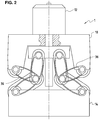
- FIG. 2 the upper part of a powder press 1 is shown, from which the arrangement of solid joints 36 in the toggle drive 16 is visible.
- solid state joints 36 shown in detail schematically.
- solid joints 36 are known in the context of solid-state joint assemblies.
- a solid-body joint is generally understood to mean a body which comprises a site with reduced rigidity. The reduced stiffness is usually realized by a local reduction in cross section or by a suitable shaping.
- FIG. 3 is a solid-state hinge 36, an elongated element which is mirror-symmetrical to a longitudinal axis 38.
- bearing receptacles 40 are formed, in which shafts or axles can be accommodated in bearings.
- struts 42 are provided between the bearing receptacles, which span between them, for example, an elliptical shape or a diamond shape.
- Other shapes are conceivable, on the one hand, a certain flexibility in one area and, on the other hand, a rigidity overall, so that a plurality of struts with a possibly reinforced central area can be provided. Due to the shape of the solid-body joint 36, when the struts 42 are compressed, ie when the pressure is applied perpendicular to the longitudinal axis 38, a distance between the bearing receptacles 40 can be changed, in particular increased.
- a fixed stopper 50 is shown to set a final press position.
- a press position circumscribes a position of the components of the tool used in a press, stamping being preferred dipping from both sides into a die opening and compressing a compressible material filled therein.
- a Pressend ein is a position in which preferably the maximum pressing force acts on the stamp on the material located in the die opening.
- punch carriers 52 are in particular fixed and force-transmitting on fixed stops.
- the use of height-adjustable fixed stop devices 50 is advantageous.
- a punch arrangement for example the upper punch arrangement 14, generally comprises punch carrier 52 and on each of which a punch (not shown) is placed.
- the punch carrier 52 has a top surface, which is preferably annular, so that through a central through hole 56 further inside punch or stamps associated elements are passed.
- the arrangement is preferably rotationally symmetrical about the press axis 18, along which the punches are movable.
- an adjusting ring 58 is shown, which is designed to adjust the press end position. As a result, in particular a tool wear can be compensated, which otherwise leads to false pressures.
- the punch carrier 52 rests with a lower axial end face 60 on an upper end face 62, ie a bearing surface, of the adjusting ring 58.
- the upper end face 62 is formed for the associated punch carrier 52 as a screw-ramp in the form of a catchy screw, and the gear ends 64 and 66 of the screw, comprising a passage, are connected by a vertical connecting surface 68.
- the corresponding axial lower end face 60 of the punch carrier 52 is designed to be complementary.
- the operative connection can be provided by means of corresponding toothing of adjusting ring 58 and drive wheel of the adjusting drive 70.
- the adjusting drive 70 may be an electric actuator, which is an individual Determination of Pressend ein allows.
- a plurality of adjusting drives 70 can also be coordinated with one another, so that a synchronous height adjustment of a plurality of punch carriers 52 is achieved.
- FIG. 5 shows a force-displacement diagram 80 for illustrating a pressing process in the powder press 1.
- the force-displacement diagram is denoted by 82, the y-axis, which is assigned to the applied force.
- the pressing force increases and shows a progressive pressing force curve, wherein in a Pressend ein the maximum pressing force is achieved. Accordingly, a large force is to be achieved with a minimum Presshubweg in the press end position.
- This course is designated 88 in the illustration and is dependent inter alia on the compressible powder material and the filling level.
- Fig. 5 shows the force-displacement curve 90 a corresponding course of a toggle drive an adapted gear ratio.
Landscapes
- Engineering & Computer Science (AREA)
- Mechanical Engineering (AREA)
- Manufacturing & Machinery (AREA)
- Press Drives And Press Lines (AREA)
Priority Applications (6)
| Application Number | Priority Date | Filing Date | Title |
|---|---|---|---|
| ES18158665T ES2983455T3 (es) | 2018-02-26 | 2018-02-26 | Prensa de polvo con accionamiento de palanca articulada y accionamiento eléctrico |
| EP18158665.2A EP3530446B1 (fr) | 2018-02-26 | 2018-02-26 | Presse à poudre dotée de levier à genouillère et d'entraînement électrique |
| PCT/EP2019/054620 WO2019162511A1 (fr) | 2018-02-26 | 2019-02-25 | Presse à poudre à entrainement à genouillère et à entrainement électrique |
| CN201980015606.3A CN111770831B (zh) | 2018-02-26 | 2019-02-25 | 具有肘杆驱动器和电驱动器的粉末压机 |
| JP2020544857A JP7419242B2 (ja) | 2018-02-26 | 2019-02-25 | トグルレバー駆動部と電気駆動部を備えた粉末プレス機 |
| US16/968,853 US11820094B2 (en) | 2018-02-26 | 2019-02-25 | Powder press having toggle lever drive and electric drive |
Applications Claiming Priority (1)
| Application Number | Priority Date | Filing Date | Title |
|---|---|---|---|
| EP18158665.2A EP3530446B1 (fr) | 2018-02-26 | 2018-02-26 | Presse à poudre dotée de levier à genouillère et d'entraînement électrique |
Publications (2)
| Publication Number | Publication Date |
|---|---|
| EP3530446A1 true EP3530446A1 (fr) | 2019-08-28 |
| EP3530446B1 EP3530446B1 (fr) | 2024-05-01 |
Family
ID=61283095
Family Applications (1)
| Application Number | Title | Priority Date | Filing Date |
|---|---|---|---|
| EP18158665.2A Active EP3530446B1 (fr) | 2018-02-26 | 2018-02-26 | Presse à poudre dotée de levier à genouillère et d'entraînement électrique |
Country Status (6)
| Country | Link |
|---|---|
| US (1) | US11820094B2 (fr) |
| EP (1) | EP3530446B1 (fr) |
| JP (1) | JP7419242B2 (fr) |
| CN (1) | CN111770831B (fr) |
| ES (1) | ES2983455T3 (fr) |
| WO (1) | WO2019162511A1 (fr) |
Families Citing this family (4)
| Publication number | Priority date | Publication date | Assignee | Title |
|---|---|---|---|---|
| USD1032674S1 (en) * | 2022-12-21 | 2024-06-25 | Zhuobin Zhou | Powder press |
| USD1097683S1 (en) * | 2024-06-07 | 2025-10-14 | Barista Technology B.V. | Coffee tamper |
| CN120038974A (zh) * | 2025-04-24 | 2025-05-27 | 成都正西智能装备集团股份有限公司 | 一种船身侧板专用液压机及其压制方法 |
| CN120115692B (zh) * | 2025-05-14 | 2025-08-29 | 江西理工大学 | 一种复合烧结磁体压制成型装置 |
Citations (11)
| Publication number | Priority date | Publication date | Assignee | Title |
|---|---|---|---|---|
| EP0436792A2 (fr) * | 1990-01-09 | 1991-07-17 | Dorst Maschinen und Anlagenbau Otto Dorst und Dipl.-Ing Walter Schlegel GmbH & Co. | Presse pour fabriquer des articles pressés en matière pulvérulente à dimensions exactes |
| US5176923A (en) * | 1989-07-24 | 1993-01-05 | Ito Kogyo Kabushiki Kaisha | Mold-pressing apparatus incorporating electric servo motor and linking mechanism |
| DE4401499A1 (de) * | 1994-01-20 | 1995-08-03 | Haendle Gmbh & Co Kg | Presse zum Verpressen keramischer Massen, insbesondere zum Herstellen von Dachziegeln |
| JP2001259896A (ja) | 2000-03-13 | 2001-09-25 | Kohtaki Seiki Kk | 粉末成形プレス |
| JP2001300778A (ja) * | 2000-04-14 | 2001-10-30 | Amino:Kk | リンク式サーボプレス |
| JP2002103089A (ja) * | 2000-09-29 | 2002-04-09 | Komatsu Ltd | プレス機械 |
| EP1422050A2 (fr) | 2002-11-22 | 2004-05-26 | Dorst Maschinen- u. Anlagenbau GmbH & Co. KG | Dispositif pour fabriquer des articles pressés conservant leur dimension à partir de matières pulvérulentes |
| DE102004052007A1 (de) * | 2004-10-25 | 2006-04-27 | Müller Weingarten AG | Antriebssystem einer Umformpresse |
| US20090317507A1 (en) | 2007-02-26 | 2009-12-24 | Rom Eisenberg | Press for producing powder based parts using compaction |
| EP2311587A1 (fr) | 2009-10-13 | 2011-04-20 | Osterwalder AG | Presse à poudre |
| EP2998989A1 (fr) * | 2014-09-18 | 2016-03-23 | ASM Technology Singapore Pte Ltd. | Presse de moulage et plateau pour une presse de moulage |
Family Cites Families (13)
| Publication number | Priority date | Publication date | Assignee | Title |
|---|---|---|---|---|
| JPH0357592A (ja) * | 1989-07-24 | 1991-03-12 | Ito Kogyo Kk | 電気サーボモータ及びリンク機構を有するモールドプレス装置 |
| JP2555939Y2 (ja) * | 1991-08-12 | 1997-11-26 | 京セラ株式会社 | セラミックの自動プレス成形装置 |
| JP2897658B2 (ja) * | 1994-10-04 | 1999-05-31 | 村田機械株式会社 | トグル式パンチプレスの異常検出装置 |
| JP2001030078A (ja) * | 1999-07-21 | 2001-02-06 | Komatsu Ltd | 熱切断機の倣い装置 |
| JP2004314118A (ja) | 2003-04-15 | 2004-11-11 | Kyoho Mach Works Ltd | 加圧装置 |
| US20050252269A1 (en) * | 2004-05-12 | 2005-11-17 | Sawdon Edwin G | Toggle press |
| JP2006055866A (ja) | 2004-08-18 | 2006-03-02 | Hoden Seimitsu Kako Kenkyusho Ltd | 電動プレス装置 |
| JP3132889U (ja) | 2007-04-12 | 2007-06-21 | 伊藤工業株式会社 | サーボプレス装置 |
| CN201058497Y (zh) * | 2007-06-14 | 2008-05-14 | 荣成金辰机械制造有限公司 | 多连杆压力机的滑块驱动装置 |
| DE102008028652B3 (de) * | 2008-06-18 | 2010-01-14 | Schuler Pressen Gmbh & Co. Kg | Pressendirektantrieb |
| JP6125405B2 (ja) * | 2012-12-25 | 2017-05-10 | 住友重機械工業株式会社 | 射出成形機 |
| US9481026B2 (en) * | 2014-10-27 | 2016-11-01 | Tyco Electronics Corporation | Press device with adjustment mechanism |
| CN206264399U (zh) * | 2016-10-31 | 2017-06-20 | 南京工程学院 | 一种双点多连杆压力机驱动机构 |
-
2018
- 2018-02-26 ES ES18158665T patent/ES2983455T3/es active Active
- 2018-02-26 EP EP18158665.2A patent/EP3530446B1/fr active Active
-
2019
- 2019-02-25 US US16/968,853 patent/US11820094B2/en active Active
- 2019-02-25 JP JP2020544857A patent/JP7419242B2/ja active Active
- 2019-02-25 WO PCT/EP2019/054620 patent/WO2019162511A1/fr not_active Ceased
- 2019-02-25 CN CN201980015606.3A patent/CN111770831B/zh active Active
Patent Citations (11)
| Publication number | Priority date | Publication date | Assignee | Title |
|---|---|---|---|---|
| US5176923A (en) * | 1989-07-24 | 1993-01-05 | Ito Kogyo Kabushiki Kaisha | Mold-pressing apparatus incorporating electric servo motor and linking mechanism |
| EP0436792A2 (fr) * | 1990-01-09 | 1991-07-17 | Dorst Maschinen und Anlagenbau Otto Dorst und Dipl.-Ing Walter Schlegel GmbH & Co. | Presse pour fabriquer des articles pressés en matière pulvérulente à dimensions exactes |
| DE4401499A1 (de) * | 1994-01-20 | 1995-08-03 | Haendle Gmbh & Co Kg | Presse zum Verpressen keramischer Massen, insbesondere zum Herstellen von Dachziegeln |
| JP2001259896A (ja) | 2000-03-13 | 2001-09-25 | Kohtaki Seiki Kk | 粉末成形プレス |
| JP2001300778A (ja) * | 2000-04-14 | 2001-10-30 | Amino:Kk | リンク式サーボプレス |
| JP2002103089A (ja) * | 2000-09-29 | 2002-04-09 | Komatsu Ltd | プレス機械 |
| EP1422050A2 (fr) | 2002-11-22 | 2004-05-26 | Dorst Maschinen- u. Anlagenbau GmbH & Co. KG | Dispositif pour fabriquer des articles pressés conservant leur dimension à partir de matières pulvérulentes |
| DE102004052007A1 (de) * | 2004-10-25 | 2006-04-27 | Müller Weingarten AG | Antriebssystem einer Umformpresse |
| US20090317507A1 (en) | 2007-02-26 | 2009-12-24 | Rom Eisenberg | Press for producing powder based parts using compaction |
| EP2311587A1 (fr) | 2009-10-13 | 2011-04-20 | Osterwalder AG | Presse à poudre |
| EP2998989A1 (fr) * | 2014-09-18 | 2016-03-23 | ASM Technology Singapore Pte Ltd. | Presse de moulage et plateau pour une presse de moulage |
Also Published As
| Publication number | Publication date |
|---|---|
| US20210016534A1 (en) | 2021-01-21 |
| CN111770831A (zh) | 2020-10-13 |
| JP7419242B2 (ja) | 2024-01-22 |
| ES2983455T3 (es) | 2024-10-23 |
| EP3530446B1 (fr) | 2024-05-01 |
| WO2019162511A1 (fr) | 2019-08-29 |
| JP2021514848A (ja) | 2021-06-17 |
| US11820094B2 (en) | 2023-11-21 |
| CN111770831B (zh) | 2023-04-04 |
Similar Documents
| Publication | Publication Date | Title |
|---|---|---|
| EP2670586B1 (fr) | Presse de pressage de pièces | |
| EP2103423B1 (fr) | Presse à poudre destinée à la fabrication d'une pièce pressée en poudre de métal | |
| DE102013109157B4 (de) | Presse zur Herstellung von Presslingen aus pulverförmigem Material | |
| EP3530446B1 (fr) | Presse à poudre dotée de levier à genouillère et d'entraînement électrique | |
| EP2694230B1 (fr) | Presse radiale | |
| EP1852247A2 (fr) | Presse destinée à la fabrication de comprimés en matériau poudreux | |
| DE10218633B3 (de) | Presse | |
| EP0724953B1 (fr) | Poinçonneuse avec espace allongé pour le montage de poinçons | |
| EP3160726B1 (fr) | Presse à châssis en c, améliorée | |
| EP2998107B1 (fr) | Entraînement de presse pour un dispositif de déformation | |
| DE10005023C2 (de) | Feinschneidpresse | |
| DE102015101586B4 (de) | Pulverpresse zur Herstellung von Presslingen aus pulverförmigem Pressmaterial | |
| WO2007006557A1 (fr) | Agencement piston-cylindre | |
| EP3530445A1 (fr) | Presse à poudre à entraînement à levier à genouillère | |
| WO2005021253A2 (fr) | Presse hydraulique | |
| AT507110A1 (de) | Presse zum umformen von material | |
| DE102010033997A1 (de) | Metall- oder Keramikpulver-Elektropresse und Steuerverfahren dafür | |
| EP2114587B1 (fr) | Presse de formage présentant une fonction de coussin pneumatique intégrée au plateau coulissant | |
| EP2851187B1 (fr) | Procédé destiné à la fabrication d'une pièce pressée en matériau pulvérulent | |
| DE102010044740A1 (de) | Metall- oder Keramikpulver-Elektropresse oder Pressenwerkzeug einer solchen Presse | |
| DE4412367A1 (de) | Schließhöhen-Justiervorrichtung für eine Presse | |
| EP1731246B1 (fr) | Appareil pour la fabrication d'une diversité des objets moulés de poudre. | |
| WO2006094485A1 (fr) | Ensemble coussin d'emboutissage a entrainement par commande numerique et a coussin hydraulique | |
| EP1344585B1 (fr) | Dispositif d'emboutissage profond hydroélastique | |
| EP3243645A1 (fr) | Dispositif de façonnage et son procédé de commande |
Legal Events
| Date | Code | Title | Description |
|---|---|---|---|
| PUAI | Public reference made under article 153(3) epc to a published international application that has entered the european phase |
Free format text: ORIGINAL CODE: 0009012 |
|
| STAA | Information on the status of an ep patent application or granted ep patent |
Free format text: STATUS: THE APPLICATION HAS BEEN PUBLISHED |
|
| AK | Designated contracting states |
Kind code of ref document: A1 Designated state(s): AL AT BE BG CH CY CZ DE DK EE ES FI FR GB GR HR HU IE IS IT LI LT LU LV MC MK MT NL NO PL PT RO RS SE SI SK SM TR |
|
| AX | Request for extension of the european patent |
Extension state: BA ME |
|
| STAA | Information on the status of an ep patent application or granted ep patent |
Free format text: STATUS: REQUEST FOR EXAMINATION WAS MADE |
|
| 17P | Request for examination filed |
Effective date: 20200124 |
|
| RBV | Designated contracting states (corrected) |
Designated state(s): AL AT BE BG CH CY CZ DE DK EE ES FI FR GB GR HR HU IE IS IT LI LT LU LV MC MK MT NL NO PL PT RO RS SE SI SK SM TR |
|
| TPAC | Observations filed by third parties |
Free format text: ORIGINAL CODE: EPIDOSNTIPA |
|
| TPAC | Observations filed by third parties |
Free format text: ORIGINAL CODE: EPIDOSNTIPA |
|
| STAA | Information on the status of an ep patent application or granted ep patent |
Free format text: STATUS: EXAMINATION IS IN PROGRESS |
|
| 17Q | First examination report despatched |
Effective date: 20221004 |
|
| GRAP | Despatch of communication of intention to grant a patent |
Free format text: ORIGINAL CODE: EPIDOSNIGR1 |
|
| STAA | Information on the status of an ep patent application or granted ep patent |
Free format text: STATUS: GRANT OF PATENT IS INTENDED |
|
| INTG | Intention to grant announced |
Effective date: 20230922 |
|
| GRAJ | Information related to disapproval of communication of intention to grant by the applicant or resumption of examination proceedings by the epo deleted |
Free format text: ORIGINAL CODE: EPIDOSDIGR1 |
|
| STAA | Information on the status of an ep patent application or granted ep patent |
Free format text: STATUS: EXAMINATION IS IN PROGRESS |
|
| GRAP | Despatch of communication of intention to grant a patent |
Free format text: ORIGINAL CODE: EPIDOSNIGR1 |
|
| STAA | Information on the status of an ep patent application or granted ep patent |
Free format text: STATUS: GRANT OF PATENT IS INTENDED |
|
| INTC | Intention to grant announced (deleted) | ||
| INTG | Intention to grant announced |
Effective date: 20240105 |
|
| GRAS | Grant fee paid |
Free format text: ORIGINAL CODE: EPIDOSNIGR3 |
|
| GRAA | (expected) grant |
Free format text: ORIGINAL CODE: 0009210 |
|
| STAA | Information on the status of an ep patent application or granted ep patent |
Free format text: STATUS: THE PATENT HAS BEEN GRANTED |
|
| AK | Designated contracting states |
Kind code of ref document: B1 Designated state(s): AL AT BE BG CH CY CZ DE DK EE ES FI FR GB GR HR HU IE IS IT LI LT LU LV MC MK MT NL NO PL PT RO RS SE SI SK SM TR |
|
| REG | Reference to a national code |
Ref country code: GB Ref legal event code: FG4D Free format text: NOT ENGLISH |
|
| REG | Reference to a national code |
Ref country code: CH Ref legal event code: EP |
|
| REG | Reference to a national code |
Ref country code: IE Ref legal event code: FG4D Free format text: LANGUAGE OF EP DOCUMENT: GERMAN |
|
| REG | Reference to a national code |
Ref country code: DE Ref legal event code: R096 Ref document number: 502018014510 Country of ref document: DE |
|
| REG | Reference to a national code |
Ref country code: LT Ref legal event code: MG9D |
|
| REG | Reference to a national code |
Ref country code: NL Ref legal event code: MP Effective date: 20240501 |
|
| PG25 | Lapsed in a contracting state [announced via postgrant information from national office to epo] |
Ref country code: IS Free format text: LAPSE BECAUSE OF FAILURE TO SUBMIT A TRANSLATION OF THE DESCRIPTION OR TO PAY THE FEE WITHIN THE PRESCRIBED TIME-LIMIT Effective date: 20240901 |
|
| PG25 | Lapsed in a contracting state [announced via postgrant information from national office to epo] |
Ref country code: BG Free format text: LAPSE BECAUSE OF FAILURE TO SUBMIT A TRANSLATION OF THE DESCRIPTION OR TO PAY THE FEE WITHIN THE PRESCRIBED TIME-LIMIT Effective date: 20240501 |
|
| PG25 | Lapsed in a contracting state [announced via postgrant information from national office to epo] |
Ref country code: FI Free format text: LAPSE BECAUSE OF FAILURE TO SUBMIT A TRANSLATION OF THE DESCRIPTION OR TO PAY THE FEE WITHIN THE PRESCRIBED TIME-LIMIT Effective date: 20240501 Ref country code: HR Free format text: LAPSE BECAUSE OF FAILURE TO SUBMIT A TRANSLATION OF THE DESCRIPTION OR TO PAY THE FEE WITHIN THE PRESCRIBED TIME-LIMIT Effective date: 20240501 |
|
| PG25 | Lapsed in a contracting state [announced via postgrant information from national office to epo] |
Ref country code: GR Free format text: LAPSE BECAUSE OF FAILURE TO SUBMIT A TRANSLATION OF THE DESCRIPTION OR TO PAY THE FEE WITHIN THE PRESCRIBED TIME-LIMIT Effective date: 20240802 |
|
| PG25 | Lapsed in a contracting state [announced via postgrant information from national office to epo] |
Ref country code: PT Free format text: LAPSE BECAUSE OF FAILURE TO SUBMIT A TRANSLATION OF THE DESCRIPTION OR TO PAY THE FEE WITHIN THE PRESCRIBED TIME-LIMIT Effective date: 20240902 |
|
| PG25 | Lapsed in a contracting state [announced via postgrant information from national office to epo] |
Ref country code: NL Free format text: LAPSE BECAUSE OF FAILURE TO SUBMIT A TRANSLATION OF THE DESCRIPTION OR TO PAY THE FEE WITHIN THE PRESCRIBED TIME-LIMIT Effective date: 20240501 |
|
| REG | Reference to a national code |
Ref country code: ES Ref legal event code: FG2A Ref document number: 2983455 Country of ref document: ES Kind code of ref document: T3 Effective date: 20241023 |
|
| PG25 | Lapsed in a contracting state [announced via postgrant information from national office to epo] |
Ref country code: PL Free format text: LAPSE BECAUSE OF FAILURE TO SUBMIT A TRANSLATION OF THE DESCRIPTION OR TO PAY THE FEE WITHIN THE PRESCRIBED TIME-LIMIT Effective date: 20240501 |
|
| PG25 | Lapsed in a contracting state [announced via postgrant information from national office to epo] |
Ref country code: LV Free format text: LAPSE BECAUSE OF FAILURE TO SUBMIT A TRANSLATION OF THE DESCRIPTION OR TO PAY THE FEE WITHIN THE PRESCRIBED TIME-LIMIT Effective date: 20240501 |
|
| PG25 | Lapsed in a contracting state [announced via postgrant information from national office to epo] |
Ref country code: PT Free format text: LAPSE BECAUSE OF FAILURE TO SUBMIT A TRANSLATION OF THE DESCRIPTION OR TO PAY THE FEE WITHIN THE PRESCRIBED TIME-LIMIT Effective date: 20240902 Ref country code: PL Free format text: LAPSE BECAUSE OF FAILURE TO SUBMIT A TRANSLATION OF THE DESCRIPTION OR TO PAY THE FEE WITHIN THE PRESCRIBED TIME-LIMIT Effective date: 20240501 Ref country code: NO Free format text: LAPSE BECAUSE OF FAILURE TO SUBMIT A TRANSLATION OF THE DESCRIPTION OR TO PAY THE FEE WITHIN THE PRESCRIBED TIME-LIMIT Effective date: 20240801 Ref country code: NL Free format text: LAPSE BECAUSE OF FAILURE TO SUBMIT A TRANSLATION OF THE DESCRIPTION OR TO PAY THE FEE WITHIN THE PRESCRIBED TIME-LIMIT Effective date: 20240501 Ref country code: LV Free format text: LAPSE BECAUSE OF FAILURE TO SUBMIT A TRANSLATION OF THE DESCRIPTION OR TO PAY THE FEE WITHIN THE PRESCRIBED TIME-LIMIT Effective date: 20240501 Ref country code: IS Free format text: LAPSE BECAUSE OF FAILURE TO SUBMIT A TRANSLATION OF THE DESCRIPTION OR TO PAY THE FEE WITHIN THE PRESCRIBED TIME-LIMIT Effective date: 20240901 Ref country code: HR Free format text: LAPSE BECAUSE OF FAILURE TO SUBMIT A TRANSLATION OF THE DESCRIPTION OR TO PAY THE FEE WITHIN THE PRESCRIBED TIME-LIMIT Effective date: 20240501 Ref country code: GR Free format text: LAPSE BECAUSE OF FAILURE TO SUBMIT A TRANSLATION OF THE DESCRIPTION OR TO PAY THE FEE WITHIN THE PRESCRIBED TIME-LIMIT Effective date: 20240802 Ref country code: FI Free format text: LAPSE BECAUSE OF FAILURE TO SUBMIT A TRANSLATION OF THE DESCRIPTION OR TO PAY THE FEE WITHIN THE PRESCRIBED TIME-LIMIT Effective date: 20240501 Ref country code: BG Free format text: LAPSE BECAUSE OF FAILURE TO SUBMIT A TRANSLATION OF THE DESCRIPTION OR TO PAY THE FEE WITHIN THE PRESCRIBED TIME-LIMIT Effective date: 20240501 Ref country code: RS Free format text: LAPSE BECAUSE OF FAILURE TO SUBMIT A TRANSLATION OF THE DESCRIPTION OR TO PAY THE FEE WITHIN THE PRESCRIBED TIME-LIMIT Effective date: 20240801 |
|
| PG25 | Lapsed in a contracting state [announced via postgrant information from national office to epo] |
Ref country code: DK Free format text: LAPSE BECAUSE OF FAILURE TO SUBMIT A TRANSLATION OF THE DESCRIPTION OR TO PAY THE FEE WITHIN THE PRESCRIBED TIME-LIMIT Effective date: 20240501 |
|
| PG25 | Lapsed in a contracting state [announced via postgrant information from national office to epo] |
Ref country code: EE Free format text: LAPSE BECAUSE OF FAILURE TO SUBMIT A TRANSLATION OF THE DESCRIPTION OR TO PAY THE FEE WITHIN THE PRESCRIBED TIME-LIMIT Effective date: 20240501 |
|
| PG25 | Lapsed in a contracting state [announced via postgrant information from national office to epo] |
Ref country code: CZ Free format text: LAPSE BECAUSE OF FAILURE TO SUBMIT A TRANSLATION OF THE DESCRIPTION OR TO PAY THE FEE WITHIN THE PRESCRIBED TIME-LIMIT Effective date: 20240501 |
|
| PG25 | Lapsed in a contracting state [announced via postgrant information from national office to epo] |
Ref country code: RO Free format text: LAPSE BECAUSE OF FAILURE TO SUBMIT A TRANSLATION OF THE DESCRIPTION OR TO PAY THE FEE WITHIN THE PRESCRIBED TIME-LIMIT Effective date: 20240501 Ref country code: SK Free format text: LAPSE BECAUSE OF FAILURE TO SUBMIT A TRANSLATION OF THE DESCRIPTION OR TO PAY THE FEE WITHIN THE PRESCRIBED TIME-LIMIT Effective date: 20240501 |
|
| PG25 | Lapsed in a contracting state [announced via postgrant information from national office to epo] |
Ref country code: SM Free format text: LAPSE BECAUSE OF FAILURE TO SUBMIT A TRANSLATION OF THE DESCRIPTION OR TO PAY THE FEE WITHIN THE PRESCRIBED TIME-LIMIT Effective date: 20240501 |
|
| PG25 | Lapsed in a contracting state [announced via postgrant information from national office to epo] |
Ref country code: SM Free format text: LAPSE BECAUSE OF FAILURE TO SUBMIT A TRANSLATION OF THE DESCRIPTION OR TO PAY THE FEE WITHIN THE PRESCRIBED TIME-LIMIT Effective date: 20240501 Ref country code: SK Free format text: LAPSE BECAUSE OF FAILURE TO SUBMIT A TRANSLATION OF THE DESCRIPTION OR TO PAY THE FEE WITHIN THE PRESCRIBED TIME-LIMIT Effective date: 20240501 Ref country code: RO Free format text: LAPSE BECAUSE OF FAILURE TO SUBMIT A TRANSLATION OF THE DESCRIPTION OR TO PAY THE FEE WITHIN THE PRESCRIBED TIME-LIMIT Effective date: 20240501 Ref country code: EE Free format text: LAPSE BECAUSE OF FAILURE TO SUBMIT A TRANSLATION OF THE DESCRIPTION OR TO PAY THE FEE WITHIN THE PRESCRIBED TIME-LIMIT Effective date: 20240501 Ref country code: DK Free format text: LAPSE BECAUSE OF FAILURE TO SUBMIT A TRANSLATION OF THE DESCRIPTION OR TO PAY THE FEE WITHIN THE PRESCRIBED TIME-LIMIT Effective date: 20240501 Ref country code: CZ Free format text: LAPSE BECAUSE OF FAILURE TO SUBMIT A TRANSLATION OF THE DESCRIPTION OR TO PAY THE FEE WITHIN THE PRESCRIBED TIME-LIMIT Effective date: 20240501 |
|
| REG | Reference to a national code |
Ref country code: DE Ref legal event code: R097 Ref document number: 502018014510 Country of ref document: DE |
|
| PLBE | No opposition filed within time limit |
Free format text: ORIGINAL CODE: 0009261 |
|
| STAA | Information on the status of an ep patent application or granted ep patent |
Free format text: STATUS: NO OPPOSITION FILED WITHIN TIME LIMIT |
|
| 26N | No opposition filed |
Effective date: 20250204 |
|
| PG25 | Lapsed in a contracting state [announced via postgrant information from national office to epo] |
Ref country code: SI Free format text: LAPSE BECAUSE OF FAILURE TO SUBMIT A TRANSLATION OF THE DESCRIPTION OR TO PAY THE FEE WITHIN THE PRESCRIBED TIME-LIMIT Effective date: 20240501 |
|
| PGFP | Annual fee paid to national office [announced via postgrant information from national office to epo] |
Ref country code: ES Payment date: 20250331 Year of fee payment: 8 |
|
| PG25 | Lapsed in a contracting state [announced via postgrant information from national office to epo] |
Ref country code: SE Free format text: LAPSE BECAUSE OF FAILURE TO SUBMIT A TRANSLATION OF THE DESCRIPTION OR TO PAY THE FEE WITHIN THE PRESCRIBED TIME-LIMIT Effective date: 20240501 |
|
| PG25 | Lapsed in a contracting state [announced via postgrant information from national office to epo] |
Ref country code: MC Free format text: LAPSE BECAUSE OF FAILURE TO SUBMIT A TRANSLATION OF THE DESCRIPTION OR TO PAY THE FEE WITHIN THE PRESCRIBED TIME-LIMIT Effective date: 20240501 |
|
| PG25 | Lapsed in a contracting state [announced via postgrant information from national office to epo] |
Ref country code: LU Free format text: LAPSE BECAUSE OF NON-PAYMENT OF DUE FEES Effective date: 20250226 |
|
| REG | Reference to a national code |
Ref country code: CH Ref legal event code: R14 Free format text: ST27 STATUS EVENT CODE: U-0-0-R10-R14 (AS PROVIDED BY THE NATIONAL OFFICE) Effective date: 20251110 Ref country code: CH Ref legal event code: R17 Free format text: ST27 STATUS EVENT CODE: U-0-0-R10-R17 (AS PROVIDED BY THE NATIONAL OFFICE) Effective date: 20251110 |
|
| REG | Reference to a national code |
Ref country code: CH Ref legal event code: R17 Free format text: ST27 STATUS EVENT CODE: U-0-0-R10-R17 (AS PROVIDED BY THE NATIONAL OFFICE) Effective date: 20251117 |
|
| REG | Reference to a national code |
Ref country code: DE Ref legal event code: R081 Ref document number: 502018014510 Country of ref document: DE Owner name: OSTERWALDER TECHNOLOGY AG, CH Free format text: FORMER OWNER: OSTERWALDER AG, LYSS, CH |
|
| REG | Reference to a national code |
Ref country code: BE Ref legal event code: MM Effective date: 20250228 |
|
| REG | Reference to a national code |
Ref country code: GB Ref legal event code: 732E Free format text: REGISTERED BETWEEN 20251127 AND 20251203 |
|
| PG25 | Lapsed in a contracting state [announced via postgrant information from national office to epo] |
Ref country code: BE Free format text: LAPSE BECAUSE OF NON-PAYMENT OF DUE FEES Effective date: 20250228 |
|
| PG25 | Lapsed in a contracting state [announced via postgrant information from national office to epo] |
Ref country code: IE Free format text: LAPSE BECAUSE OF NON-PAYMENT OF DUE FEES Effective date: 20250226 |
|
| REG | Reference to a national code |
Ref country code: CH Ref legal event code: U11 Free format text: ST27 STATUS EVENT CODE: U-0-0-U10-U11 (AS PROVIDED BY THE NATIONAL OFFICE) Effective date: 20260301 |
|
| PGFP | Annual fee paid to national office [announced via postgrant information from national office to epo] |
Ref country code: GB Payment date: 20260219 Year of fee payment: 9 |
|
| PGFP | Annual fee paid to national office [announced via postgrant information from national office to epo] |
Ref country code: DE Payment date: 20260218 Year of fee payment: 9 |
|
| PGFP | Annual fee paid to national office [announced via postgrant information from national office to epo] |
Ref country code: AT Payment date: 20260219 Year of fee payment: 9 |
|
| PGFP | Annual fee paid to national office [announced via postgrant information from national office to epo] |
Ref country code: IT Payment date: 20260219 Year of fee payment: 9 |
|
| PGFP | Annual fee paid to national office [announced via postgrant information from national office to epo] |
Ref country code: FR Payment date: 20260218 Year of fee payment: 9 |
|
| PGFP | Annual fee paid to national office [announced via postgrant information from national office to epo] |
Ref country code: CH Payment date: 20260301 Year of fee payment: 9 |