EP0437111A2 - Multiplexiertes, hydraulisches Steuerungssystem - Google Patents
Multiplexiertes, hydraulisches Steuerungssystem Download PDFInfo
- Publication number
- EP0437111A2 EP0437111A2 EP90314419A EP90314419A EP0437111A2 EP 0437111 A2 EP0437111 A2 EP 0437111A2 EP 90314419 A EP90314419 A EP 90314419A EP 90314419 A EP90314419 A EP 90314419A EP 0437111 A2 EP0437111 A2 EP 0437111A2
- Authority
- EP
- European Patent Office
- Prior art keywords
- hydraulic
- multiplexer
- input
- signals
- selector
- Prior art date
- Legal status (The legal status is an assumption and is not a legal conclusion. Google has not performed a legal analysis and makes no representation as to the accuracy of the status listed.)
- Granted
Links
Images



Classifications
-
- F—MECHANICAL ENGINEERING; LIGHTING; HEATING; WEAPONS; BLASTING
- F15—FLUID-PRESSURE ACTUATORS; HYDRAULICS OR PNEUMATICS IN GENERAL
- F15B—SYSTEMS ACTING BY MEANS OF FLUIDS IN GENERAL; FLUID-PRESSURE ACTUATORS, e.g. SERVOMOTORS; DETAILS OF FLUID-PRESSURE SYSTEMS, NOT OTHERWISE PROVIDED FOR
- F15B13/00—Details of servomotor systems ; Valves for servomotor systems
- F15B13/02—Fluid distribution or supply devices characterised by their adaptation to the control of servomotors
- F15B13/06—Fluid distribution or supply devices characterised by their adaptation to the control of servomotors for use with two or more servomotors
- F15B13/07—Fluid distribution or supply devices characterised by their adaptation to the control of servomotors for use with two or more servomotors in distinct sequence
-
- G—PHYSICS
- G05—CONTROLLING; REGULATING
- G05B—CONTROL OR REGULATING SYSTEMS IN GENERAL; FUNCTIONAL ELEMENTS OF SUCH SYSTEMS; MONITORING OR TESTING ARRANGEMENTS FOR SUCH SYSTEMS OR ELEMENTS
- G05B19/00—Program-control systems
- G05B19/02—Program-control systems electric
- G05B19/18—Numerical control [NC], i.e. automatically operating machines, in particular machine tools, e.g. in a manufacturing environment, so as to execute positioning, movement or co-ordinated operations by means of program data in numerical form
- G05B19/414—Structure of the control system, e.g. common controller or multiprocessor systems, interface to servo, programmable interface controller
-
- G—PHYSICS
- G05—CONTROLLING; REGULATING
- G05B—CONTROL OR REGULATING SYSTEMS IN GENERAL; FUNCTIONAL ELEMENTS OF SUCH SYSTEMS; MONITORING OR TESTING ARRANGEMENTS FOR SUCH SYSTEMS OR ELEMENTS
- G05B19/00—Program-control systems
- G05B19/43—Program-control systems fluidic
- G05B19/46—Program-control systems fluidic hydraulic
-
- Y—GENERAL TAGGING OF NEW TECHNOLOGICAL DEVELOPMENTS; GENERAL TAGGING OF CROSS-SECTIONAL TECHNOLOGIES SPANNING OVER SEVERAL SECTIONS OF THE IPC; TECHNICAL SUBJECTS COVERED BY FORMER USPC CROSS-REFERENCE ART COLLECTIONS [XRACs] AND DIGESTS
- Y10—TECHNICAL SUBJECTS COVERED BY FORMER USPC
- Y10T—TECHNICAL SUBJECTS COVERED BY FORMER US CLASSIFICATION
- Y10T137/00—Fluid handling
- Y10T137/8593—Systems
- Y10T137/86911—Sequential distributor or collector type
-
- Y—GENERAL TAGGING OF NEW TECHNOLOGICAL DEVELOPMENTS; GENERAL TAGGING OF CROSS-SECTIONAL TECHNOLOGIES SPANNING OVER SEVERAL SECTIONS OF THE IPC; TECHNICAL SUBJECTS COVERED BY FORMER USPC CROSS-REFERENCE ART COLLECTIONS [XRACs] AND DIGESTS
- Y10—TECHNICAL SUBJECTS COVERED BY FORMER USPC
- Y10T—TECHNICAL SUBJECTS COVERED BY FORMER US CLASSIFICATION
- Y10T137/00—Fluid handling
- Y10T137/8593—Systems
- Y10T137/87169—Supply and exhaust
- Y10T137/87193—Pilot-actuated
- Y10T137/87201—Common to plural valve motor chambers
-
- Y—GENERAL TAGGING OF NEW TECHNOLOGICAL DEVELOPMENTS; GENERAL TAGGING OF CROSS-SECTIONAL TECHNOLOGIES SPANNING OVER SEVERAL SECTIONS OF THE IPC; TECHNICAL SUBJECTS COVERED BY FORMER USPC CROSS-REFERENCE ART COLLECTIONS [XRACs] AND DIGESTS
- Y10—TECHNICAL SUBJECTS COVERED BY FORMER USPC
- Y10T—TECHNICAL SUBJECTS COVERED BY FORMER US CLASSIFICATION
- Y10T137/00—Fluid handling
- Y10T137/8593—Systems
- Y10T137/87169—Supply and exhaust
- Y10T137/87193—Pilot-actuated
- Y10T137/87209—Electric
Definitions
- This invention relates to hydraulic control systems, and more particularly to such systems in which a plurality of hydraulic actuators are to be precisely positioned in dependence on the magnitude of a similar plurality of electrical control signals.
- each hydraulic actuator was provided with a device to convert an electrical input signal into a mechanical actuator position.
- the torque motor being dedicated to the associated actuator, could be driven for as long as additional actuator movement was desired.
- both torque motors and servo valves are fairly expensive, and both are fairly weighty components, particularly for aircraft applications where weight savings on the order of pounds can translate into substantial operating cost savings over the life of the aircraft.
- the pilot valve has a spool which is rotated for multiplexing and which is positioned vertically by the torque motor to establish control positions.
- the spool and valve would be modified to provide a plurality of outlet ports at different angular positions of the spool such that the vertical control position of the valve combined with a plurality of angular multiplex positions could be used to sequentially deliver hydraulic fluid to a plurality of actuators.
- a position sensor on the rotary multiplexer would be used to coordinate multiplexed electrical signals for the pilot valve with the time slots of the multiplexer.
- Multiplexing of hydraulic circuits is not broadly new. It can be used for example in sharing a single transducer among a number of hydraulic or pneumatic channels, such as illustrated in Moore et al. U.S. patent 3,645,141.
- the opportunity to share a control servo valve among multiple actuators is also suggested in the literature, but on a manually controlled rather than a simultaneous multiplexed real time basis, insofar as applicant is aware.
- control is being maintained over all of the channels, while servicing those channels individually and separately, but with sufficient frequency to maintain the outputs as representative of the inputs in substantially real time.
- each of the channels must be serviced in their assigned sequence and for the duration of their assigned time slot, even if service for the former is inadequate and service for the latter is superfluous.
- Yet another object of the invention is to provide a reliable highly accurate multiplexed hydraulic control system which not only can randomly address the channels which it services, but which utilizes digital signals which can be derived from a controlling computer to address the respective channels.
- the multiplexing valve has a control input which is responsive to a source of binary selector signals, such selector signals being used to directly address any particular channel connected to the multiplexer.
- the system also includes means for modulating a hydraulic signal in accordance with selected ones of a plurality of electrical control signals, and applying the modulated hydraulic signal to the multiplexer common input. Control means then coordinates the addressing of the multiplexer with the modulating of the hydraulic signal to assure that hydraulic signals of the appropriate magnitude are coupled to each addressed channel, thereby to control all of the channels in accordance with the control signals for each channel.
- multi-bit binary selector signals are provided for controlling the multiplexer, and each selector signal has a binary value which corresponds to its associated channel of the multiplexer.
- the multiplexer can, if desired, be run randomly, and in order to randomly activate a selected channel, it is simply necessary to address that channel to cause the multiplexer to direct controlled fluid flow to the output port which services the addressed channel.
- the computerized control which is typically associated with such devices has exceptional flexibility in controlling its channels.
- the control can be configured, for example, to access particular channels only when those channels demand service, to prioritize certain channels related to equipment whose movement is more critical than that of others, or to alter a normal pattern of port access in abnormal situations.
- the multiplexer driver need require no complex drive circuitry, it being necessary to simply select the appropriate binary addresses and couple them to the multiplexer at the appropriate time and at the appropriate level.
- the multiplexer itself is also simplified, using simple and inexpensive elements, such as ordinary solenoid operated valves, which can be produced to operate with the high reliability demanded of jet aircraft controls.
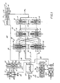
- Fig. 1 shows a first embodiment of a multiplexed hydraulic control system exemplifying the present invention. More particularly, Fig. 1 illustrates a multiplexed hydraulic control system 20 including multiplexing means 21, a common source of hydraulic fluid 22 which is modulated in accordance with a plurality of electrical control signals relating to the respective channels, the channels being illustrated only in part and designated generally by reference numeral 23.
- the multiplexer means 21 is responsive to a source of multi-bit binary selector signals for individually addressing the respective channels, such source being illustrated as microprocessor 25.
- the microprocessor outputs a multi-bit binary address on an output bus 26 which is coupled to electrical actuators generally indicated at 27 for driving valve means in the multiplexer 21 to individually and selectively activate the channel whose address appears on the bus 26.
- the multiplexer means 21 is shown as a logic tree having three levels 30, 31, 32, each level including a spool valve and an electrical operator for positioning the spool.
- each level including a spool valve and an electrical operator for positioning the spool.
- the lowermost level 30 which responds to the least significant bit of the address word
- a solenoid 34 which actuates a pair of valves 35, 36.
- the level 30 is illustrated with the solenoid 34 in the energized condition, in which condition the valve section 35 is open to pass fluid from the hydraulic control source 22, and the valve 36 is closed blocking fluid flow to its output.
- first stage valve members 35, 36 are coupled to selected inputs of second stage valve members 40, 41 whose position is controlled by an actuating solenoid 42.
- the outputs of valves 40, 41 are coupled as inputs to selected inputs of upper stage valves 44, 45 whose position is controlled by an actuating solenoid 46 in response to the level of the most significant bit of the address word.
- solenoids 34 and 46 are energized while solenoid 42 is not.
- solenoid 42 is not.
- the upper sections 35, 44 of the valves associated with solenoids 34 and 46 are open whereas the lower section 41 associated with de-energized solenoid 42 is open.
- the binary signals applied to solenoids 34, 42 and 46 are decoded by the logic tree in which the valves are connected to individually activate the addressed channel.
- the logic tree in which the valves are connected to individually activate the addressed channel.
- a binary 7 were coupled on the address bus 26 to the solenoids in the multiplexer, a path would be traced through the upper section of each upper valve 35, 40 and 44 to the channel 7 output of the upper stage 32.
- valve tree in order to operate additional channels. For example, if one more level were added, the system could be capable of controlling 16 channels and would require use of a 4-bit address word.
- the multiplexed hydraulic control system is the function of the multiplexed hydraulic control system to pass modulated hydraulic flow to the respective channels for controlling the positions of actuators in those channels in accordance with a plurality of electrical control signals.
- the electrical control signals are also produced by the microprocessor 25, and are coupled serially onto a bus 50 to a linear actuator 51 which controls the position of a spool 52 in a spool valve 53.
- the microprocessor 25 generates signals which are a function of the demanded position (see inputs 55) and the actual position of each actuator (see inputs 56), and when it is desired to reposition an actuator couples an electrical signal onto the bus 50 for positioning the spool 51 in the valve 53 which acts as a pilot to control flow from either source PC or to sump PB via an output port 54 of the valve 53.
- the magnitude of the signal on the bus 50 controls the position of the valve and thus the rate and direction of hydraulic flow through the output port 54.
- the microprocessor 25 is coupling the electrical control signals on the bus 50 to adjust the magnitude of the modulated hydraulic signal in the output port 54, it is simultaneously coupling address signals on the address bus 26 for setting up the multiplexer 21 to select the channel associated with the control signal on the bus 50.
- the concurrence of the control signal on the bus 50 which modulates the hydraulic flow and the address signal on bus 26 which selects the channel to receive that flow allows the microprocessor 25 to control any of the channels serviced by the system.
- Those channels can be controlled in a repeating sequence in time division multiplexed fashion, or as noted above, the microprocessor can sense conditions in the channels as well as other conditions on demand inputs 55 to determine a non-repetitive sequence for adjusting the actuators in the channels.
- the output 54 of the pilot valve 53 can be connected directly to the inlet of the lowest level 30 of the logic tree as illustrated in connection with Fig. 1.
- the modulated flow will be physically switched through the logic tree and coupled directly from the addressed output of the logic tree to the associated channel.
- the logic tree can be used to switch an unmodulated hydraulic signal derived from the high pressure source PC, and to utilize the multiplexer outputs to control small hydraulic selector valves, one in each channel.
- the channel 5 is the activated channel in the illustrated condition of the multiplexer
- the common source of hydraulic flow from the valve 53 is connected through the multiplexer 21 to a control chamber 62a of a second stage valve 62.
- Flow into or out of the control chamber 62a controls the position of a spool 63, which, by means of metering land 63a, controls flow from source PC or sump PB through an outlet port 64 which in turn positions the output actuator 65.
- the spool 63 is positioned such that the metering land 63a has the output port 64 partially opened to sump PB such that in the illustrated condition fluid is being moved at a rate controlled by the position of land 63a from the chamber 68 of the actuator.
- the second stage valve 62 among the functions of the second stage valve 62 are to provide hydraulic amplification (a rather small flow into the control chamber 62a can control a much larger flow directly from source or sump to the output port 64).
- a second function of the second stage valve in addition to providing amplification, is to provide the possibility for continuous flow in the channel to the actuator, not only during the time slot which is assigned to the channel but also when the multiplexer is servicing other channels.
- the second stage valve 62 has its spool 63 locked in its last position whenever fluid flow into or out of the control chamber 62a is terminated, leaving the possibility for continued flow through the output port 64 even when the second stage valve 62 is not receiving additional fluid.
- the output actuator 65 has a piston 66 which is positioned by flow from the second stage valve into a chamber 68 to drive the piston 66 upwardly as fluid is added to the chamber 68 or to allow the piston to fall downwardly when fluid is removed from the chamber 68.
- An intermediate source of regulated pressure PCR coupled to the upper chamber 67 serves as a hydraulic spring to force the piston 66 downwardly when fluid is removed from the chamber 68, or to allow the piston 66 to move upwardly when fluid is added.
- Mechanically coupled to the piston is feedback means 69 which produces an electrical signal coupled back to the microprocessor 25 via one of the feedback inputs 56.
- the signal produced by feedback means 69 relates to both the actual position of the actuator operator and the rate of movement of the actuator operator.
- the rate information is important in stabilizing the control loop which includes a second stage valve driving an actuator, both of which are integrators. To the extent necessary, the disclosure of said copending application is incorporated herein by reference.
- the second stage valve 70 is coupled to non-activated channel 1 and thus the input of the second stage valve 70 remains cut off from the control source.
- no additional modulated flow is passed to the associated second stage valve 70 and the spool 71 of that second stage valve remains in its previously adjusted position allowing flow to the associated actuator 72 as determined by the prior adjustment made by the microprocessor 25.
- the metering land 71a has slightly opened the output port to the source PC, continuing to pump additional fluid into the control chamber 72a of hydraulic actuator 72.
- the microprocessor 25 Whenever it is desired to change the direction or rate of movement of the actuator 72, the microprocessor 25 simply needs to address channel 1 on the address bus 26 and couple a control signal on the control bus 50 of the appropriate magnitude to either pass additional fluid to the second stage valve 70 thereby decreasing flow rate therethrough or withdraw fluid from the second stage valve 70 to increase flow rate therethrough.
- Fig. 1 The system of Fig. 1 is illustrated in schematic form, and configuring mechanical equipment to accomplish the functions described in detail above can make use of certain options in reducing the amount of equipment required.
- the system is not of minimum configuration in order to illustrate certain optional features which can be used when desired.
- the upper and lower valve sections can be combined into a single unit by having a single inlet port controlled by a valve spool to be switched to either of two closely adjacent outlets depending on whether the solenoid is activated or deactivated.
- the electrical equivalent of this suggested modification is replacing a pair of single pole single throw switches with one single pole double throw switch.
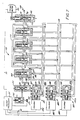
- Fig. 2 there is shown a further embodiment of the present invention which employs a multiple stage logic tree of valves of a different type. More particularly, at the right of Fig. 2 there is shown an inlet 54a which is to be connected to a modulated source of hydraulic fluid such as the output 54 of the pilot valve 53 of the Fig. 1 embodiment.
- the multiplexer section 73 of Fig. 2 is comprised of three levels 74, 75, 76 and therefore in binary fashion is capable of controlling fluid flow in eight channels.
- Only one of those channels, lowermost channel 0, is illustrated in its entirety as having an output 77 from the lowermost valve in the third level 76 (channel 0), and is shown to include a second stage valve 78 driven directly from the output 77.
- the second stage valve 78 is connected to the high pressure source PC and sump PB for controllably providing fluid flow to an actuator 79 having both position and rate feedback sensors 79a fed back to the controlling microprocessor 25.
- Each of the other valves for channels 1 through 7 is shown having an associated output, but in order to avoid overcomplicating the drawing, the second stage valve, hydraulic actuator, and feedback sensor for those channels are omitted.
- Fig. 2 illustrates use of a valve of a different type, commonly called a flapper valve and having the advantage over the spool valves of Fig. 1 of minimization of valve member mass, and elimination of chip shear problems.
- valve 74a in the lowest level 71 the valve is seen to include a valve body 80 having a pivot point 81 on which a flapper mechanism 82 is mounted. In the illustrated position, the flapper is in its raised condition in which it maintains a first output port 83 in the closed position while opening a second output port 84 for receiving modulated flow from an inlet 85 connected to the modulated source 54a.
- the valve includes an electrical operator 86 shown in the illustrated embodiment as a rotary voice coil having a stationary electrical coil 87 in which is mounted a central floating diaphragm 88 which can be pivoted from the rest or quiescent condition illustrated in Fig. 2 to its uppermost dotted line position when the coil 86 is energized. Since an arm 89 connects the movable diaphragm 88 to the pivotable flapper 82, when the coil is energized the flapper member 82 is pivoted to its alternate dotted line position in which output port 83 is opened to receive inlet modulated flow and outlet port 84 is closed.
- the flapper valves in the higher levels 75, 76 are similar to the valve 74a in the lowest level 74, except that each of those levels has but a single electrical actuator driving multiple flapper valve assemblies.
- the second level 72 has a single electrical voice coil 90 driving a pair of flapper valves 91, 92; the fact that the drive is common is illustrated by dashed line interconnection 93.
- the uppermost level includes four valves 94, 95, 96 and 97, all driven by a single electrical actuator 98 ganged by means of dashed line connection 99 to the actuators of each of the flapper valves in that level.
- Figs. 3-6 better illustrate the mechanical configuration of such a system, and further demonstrate the compactness which can be achieved in a multiple level logic tree valving arrangement such as schematically illustrated in connection with Fig. 2.
- a multiple level logic tree valving arrangement such as schematically illustrated in connection with Fig. 2.
- valves can be and typically are fairly miniaturized, often being only about 2 inches or even less in diameter.
- Fig. 3 like Fig. 2, illustrates the multiple level logic tree including lowest level 74, intermediate level 75 and highest level 76 weighted in binary fashion. Accordingly, coupling of address signals by the microprocessor 25 onto address bus 26 will serve to apply a binary address to the multiplexer, which in turn will create a single path through the multiplexer identified by the address, thereby coupling the input to the addressed output.
- the lowest level 74 includes only a single flapper valve 80 illustrated in the same fashion as the lowest level valve 80 in the Fig. 2 embodiment, except that in the Fig. 3 embodiment the voice coil 86 is energized opening output port 83.
- the second level 75 of the logic tree is seen to include a pair of flapper valve sections formed in a single valve body 110, the flapper valve operators being indicated at 111, 112.
- a single voice coil 90 shown energized in the Fig. 3 embodiment, causes the simultaneous pivoting of the flapper members 111, 112 to controllably open or close their output ports.
- the highest level 76 of the logic tree is formed on a single valve body 120 which, in this case, utilizes four flapper operators 121-124, all pivoted in unison about a single pivot point 125.
- the voice coil 98 for the upper stage is also illustrated in the energized condition, and when de-energized the four flapper members will assume their opposite position to open the ports which are illustrated as closed, and close those illustrated as open.
- the channel 130 includes a second stage valve 131 controlled by modulated fluid flow directed to the channel from the flapper valve multiplexer. Flow through the second stage valve in turn controls the motion of a hydraulic actuator 132 having feedback means 133 coupled thereto for providing a feedback signal back to the microprocessor 25.
- the channel 130 illustrates an alternate output configuration utilizing double-acting actuators 132 driven by second stage valves 131 having paired outputs for simultaneously supplying both pressure and sump to the respective chambers of the actuator 130 so that full power is applied to the actuator in both the advance and retract directions. Recalling that in the Fig. 3 illustration all of the valves are shown energized, it will be appreciated that the channel 130 illustrated in detail is channel 7, the highest addressed channel in that system. Channel numbers are also provided at the outputs of the multiplexer ports which service those channels.
- Fig. 3 shows an alternative means for modulating a hydraulic signal which, in keeping with the rotary nature of the flapper valves, is also a rotary valve generally indicated at 140.
- the valve 140 has an electrical actuator 141 illustrated in the form of a rotary voice coil, but the rotary voice coil 141, in the preferred embodiment, is not simply a two-position device, but has its position infinitely variable based upon the level of the signal coupled to it.
- the rotary voice coil is linked by arm 142 to a rotary valve member 143 which selectively couples either the high pressure hydraulic source PC or hydraulic sump PB to an outlet port 145 which serves to provide the modulated hydraulic input signal to the common source 54a of the logic tree.
- valve member 143 is rotated to open or close the outlet port 145 to greater or lesser degree to produce controlled flow from the source PC or to the sump PB.
- FIG. 4 shows an elevational view of the system of Fig. 3 in which a single valve body 148 is used for mounting not only the rotary multiplexing valve 140, but also each of the valve sections 74, 75, 76. It is seen that each of the pivot points, such as pivot point 81 for the valve section 74, pivot point 143 for the multiplexer valve 140, pivot point 125 for the upper section 76 are each mounted for rotation within the valve body 148 for adjusting the position of respective valve elements or flappers in accordance with the structure and function described in connection with Fig. 3.
- valve outputs 0 through 8 are taken from the highest level valve section 76 which is best illustrated in Fig. 5 while the intermediate porting between the valves is also illustrated in the diagrams of Figs. 4-6.
- the same reference numerals are utilized in Figs. 4-6 as in Fig. 3 and the description of those elements and their interrelationship will not be repeated here.
- the figure does illustrate that the entire system of Fig. 3 (less the electronics and the channel equipment) can be configured in a relatively small block occupying a cube measuring only about 2 inches by about 2 inches by about 4 inches. The resulting weight and space saving will be appreciated when it is recalled that such a valving arrangement not only produces the modulated fluid flow necessary for control of one channel, but utilizes that modulated fluid flow for control of 8 individual channels.
- Fig. 7 represents a further embodiment of the invention which differs from the embodiments described above in a number of respects.
- the embodiment does contain a multiplexer having a common input and a plurality of individually selectable outputs
- the multiplexer is not in the form of a logic tree.
- the common input is simply a connection or manifold supplying a plurality of gate type valves in the multiplexer with fluid from the common source of modulated hydraulic fluid.
- the source of multi-bit binary addressing signals is a hydraulic source to produce hydraulic binary addressing signals, which hydraulic source may or may not include electrical actuators for translating binary electrical addressing signals produced by the microprocessor into the necessary binary hydraulic signals.
- a microprocessor 25 which has a number of functions including the production of a plurality of electrical control signals on its control bus 50 which are related to actuator position or changes in actuator position in the respective channels.
- the bus 50 is coupled to modulating means 150 which serves to produce modulated hydraulic signals in accordance with the electrical control signals coupled onto the bus 50.
- the modulating means 150 includes a torque motor 151, which is responsive to the succession of electrical signals, and which drives a spool valve 152.
- the vertical positioning of the spool 153 in the spool valve by the torque motor 151 adjusts the position of a land 154 which thereby controls the degree to which an output port 155 is opened and whether that port is opened to the high pressure source PC or sump PB.
- the output port is coupled to a schematically illustrated manifold 157 (which can be a unitary manifold or a series of independent connections) which serves as a common input for multiplexer means generally indicated at 158.
- the multiplexer means 158 comprises a plurality of hydraulic gates 160-163. While only four gates are illustrated in Fig. 7, utilizing a three-bit binary address as in the previous embodiments would allow for eight, and supplementing that address with an additional bit would allow for 16.
- the fact that the system provides for additional gates and channels is indicated by the heads in the hydraulic logic addressing channels indicated at 159.
- Each of the hydraulic gates 160-163 has a control input port 164-167, respectively, connected to the common source of modulated hydraulic signals 157, and an output port 170-173, respectively, connected to its associated channel.
- Fig. 7 shows the details of only a single channel, that connected to the hydraulic gate 160, and shows it, as in the prior embodiments, to include a second stage valve 175 connected to the hydraulic source PC and hydraulic sump PB for controllably delivering fluid to a hydraulic actuator 176 which is the operative element of the channel.
- the actuator 176 has a feedback device 177 coupled to the microprocessor 25 for providing position and rate of movement information to the microprocessor.
- the microprocessor 25 In addition to functioning as the source of electrical control signals, the microprocessor 25 also functions as a source of multi-bit binary selector signals for individually addressing the respective channels serviced by the multiplexer 158. To that end, as in the previous embodiments, the microprocessor 25 has a selector bus 26 onto which the multi-bit binary selector signals are coupled.
- the binary electrical signals are converted into binary hydraulic signals by hydraulic valve means generally indicated at 180.
- the hydraulic valve means 180 responds to the binary electrical signals by producing a corresponding plurality of binary hydraulic selector signals.
- the hydraulic valve means in the illustrated embodiment comprises a series of solenoid operated hydraulic valves 181-183, each having a solenoid 184-186 coupled to and driving a spool valve 187-189.
- each of the hydraulic valves 187-189 includes a pair of lands 190, 191 and a pair of outputs 192, 193.
- the source PC and drain PB hydraulic pressures are connected to the valve such that one of the outputs 192, 193 will be at source (or high) pressure and the other at sump (or low) pressure for any given condition of the associated solenoid.
- the output 192 will be at sump and the output 193 at source pressure.
- hydraulic gates 160-163 are responsive to the hydraulic logic signals produced by the valves 187-189 to selectively and individually couple the modulated hydraulic signal on the common input 157 to the addressed output.
- the gates 160-163 function as three input AND gates, for example, the gate 160 having three inputs 195, 196, 197 all feeding a common chamber 198.
- the valve will be activated connecting the modulated source at input port 164 to the output 170 and thereby to its associated second stage valve.
- any of the inputs 195-197 is at sump, there will be insufficient pressure in the chamber 198 to raise the piston and open the valve.
- selector 163 will be addressed to couple its input control port 167 to its output port 173 and thus pass modulated hydraulic fluid to the associated channel.
- the activation of selector 163 is illustrated by the raised condition of spool 163a which translates port 163b to a position where it allows fluid passage between input and output.
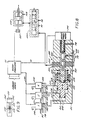
- FIG. 8 there is shown another embodiment of the present invention which also utilizes binary hydraulic control signals for operation of a hydraulic multiplexer.
- means are provided, shown in Fig. 8 as microprocessor 25, for producing two types of signals, electrical control signals which are output on bus 50 for modulating a hydraulic signal, and selector signals which are output on bus 26 for selecting the channel associated with the control signal, so that the multiplexer can pass the modulated hydraulic signal from the hydraulic modulator to the addressed channel.
- the binary electrical address signals which are output on bus 26 are coupled to a plurality of three-way solenoid operated hydraulic valves 200, 201, 202.
- the valves 201-202 each have a pair of input ports, a first port 203 being coupled to the high pressure source PC and a second port 204 being coupled to the hydraulic sump PB.
- Output ports 205, 206, 207 carry binary hydraulic addresses which are in the form of high pressure signals PC or sump signals PB depending upon whether the associated solenoid valve 200-202 is energized or de-energized. In the de-energized condition, sump PB is coupled to the output port whereas in the energized condition hydraulic source passes PC to the output.
- means are provided for responding to the hydraulic binary address signals to couple the modulated hydraulic input to the addressed hydraulic output, thereby to control the actuator position or rate of travel in the addressed channel.
- such means are provided by a hydraulically actuated cylinder 210 comprising a valve body 211 in which is mounted a hydraulically actuated piston assembly 212.
- the piston 212 has a plurality of binary weighted lands 213, 214, 215 which are disposed in the valve body in individual chambers 216, 217, 218 such that they can be individually operated.
- the areas of the lands are weighted in binary fashion, for example with the land 213 having an area of one unit, the area of land 214 being two units, and the area of land 215 being four units. If additional lands are utilized, they would each double in area from the immediately prior land to continue the binary weighting.
- output ports 220 are associated with the actuator 212 such that they are individually opened depending upon the position of the actuator 212 and how many units from its rest position it has been translated by the hydraulic address signals. It is noted that the output ports are showed only schematically in Fig. 8 since they must be mechanically tightly packed in order to achieve independent port selection with the limited actuator travel available. It will be apparent to those skilled in this art that in mechanically configuring the output ports they will be axially close together and, to accomplish that, they can be made rather long and thin and can also be circumferentially displaced from each other around the body of the valve in order to restrict the total port axial length to a length of the valve body 210 commensurate with actuator travel.
- the Fig. 8 embodiment illustrates a further integration of the hydraulic modulating means responsive to the electrical control signals with the multiplexer means.
- the valve body 211 includes a pair of inlet ports 230, 231, the port 230 being coupled to the hydraulic source PC and the port 231 to the hydraulic sump PB.
- the inner bore 232 of the valve body 211 is cylindrical, and in it is mounted for reciprocation a cylindrical valve member 233 which carries the output port 222. It is seen that the cylindrical valve member 233 is affixed to the multi-landed position 212 at 234 and thereby is translated to positions dictated by the hydraulic logic signals applied.
- the PC and PB inlets coupled to inlet ports 230, 231 are controllably passed to an internal chamber 235 formed within the valve member 233.
- the porting is indicated schematically in Fig. 9.
- a pair of elongate slots 230, 231 are found in the cylindrical valve body; it is also recalled that the slot 230 is connected to hydraulic source PC and the port 231 to hydraulic sump PB.
- a further elongate slot 242 is formed in the cylindrical valve member 233 for controllable communication with the ports 230, 231.
- control means 245 are provided in the illustrated embodiment in the form of a rotary torquer or voice coil.
- the actuator of the rotary torquer 245 is connected to the valve member 233 by means such as a splined connection which will allow the rotary torquer 245 to rotate the operator 233 but will allow the multi-landed piston 212 to translate the actuator 233 for performing the multiplexing function.
- the microprocessor 25 produces the electrical control signals described above which are coupled on bus 50 to the rotary torquer 245 to rotate the operator 233, controllably connecting the port 242 with either the ports 230 or 231, depending upon the sense and magnitude of the applied electrical signals. As a result, a modulated hydraulic flow is produced which is passed by the multiplexer to the addressed channels.
- the rotary torquer 245 can be operated in either digital fashion or in the analog fashion described in connection with the prior embodiments. In digital fashion, the rotary torquer need only have three positions, the off position indicated in Fig. 8 and a pair of on positions where the port 242 is connected to the ports 230 in one condition, or 231 in the other condition. Thus, the flow rate whenever the ports are connected will be the same, and the microprocessor 25 controls the time of actuation in order to control the modulation of the hydraulic signal. By way of contrast, in the analog implementation, as in the prior embodiments, the microprocessor 25 controls the degree to which the ports 230 or 231 are opened as a modulating mechanism.
- a control loop for a multiple channel multiplexed system in the illustrated embodiment comprising three channels.
- the Fig. 10 embodiment also illustrates a further modification in that two of the channels include conventional servo actuators with position and rate feedback means, while the third channel includes an on/off actuator which requires no feedback means.
- Such a system illustrates that one or several on/off devices can be intermixed with the controlled position actuators in the multiplexed control, and that is particularly suitable in a random access system where the control can ignore the on/off channels except on the comparatively rare occasion when it is desired to switch from one state to the other.
- an input buffer circuit 300 having three input signals coupled thereto on lines 301-303. Two of the input signals are like those described in connection with Fig. 1, i.e., have levels (typically current levels) or binary digital valves which relate to a demanded position for the associated actuator. A third signal on line 303 is simply an on/off signal which demands that the actuator in the associated channel be switched either on or off. The signals, having passed through the buffer 300, are coupled to associated control loops 305, 306, 307.
- the loops 305 and 306 are similar to each other in that they compare the associated input signal from the buffer with a feedback signal on lines 308, 309, respectively for establishing an output signal which is proportional to the flow intended to be sent to the associated second stage valve in the next cycle.
- the feedback signal is preferably both a position signal and a rate signal which, when combined with the input demand signal as will be described below, produces an output signal for controlling fluid flow to the associated actuator.
- the on/off signal from the third channel is coupled to on/off level set controller 307, and in this case needs no feedback from the associated actuator.
- the three signals on the three controllers are coupled as inputs to a signal multiplexer 310 which has a single output bus 311, operated under the control of a master controller 320 to individually introduce signals onto the output bus 311 representative of the multiplexer input signals.
- the signals can be in a sequential order, but the master controller 320 also has the ability, particularly operating in conjunction with a master computer for the aircraft, to vary not only the sequence of the signals output on the bus 311, but also their dwell time.
- the sequence of control signals whose values are to determine the flow rate to selected channels are passed through a conventional driver circuit 313 which produces modulated output signals which are used to control a modulating actuator 321.
- the modulating actuator which is responsive to an electrical signal to produce a corresponding hydraulic signal was illustrated as a torque motor or a voice coil coupled to and driving a modulating valve.
- the modulating actuator has the hydraulic source PC and sump PB connected thereto, and serves to modulate between those levels in dependence on the electrical signal provided by the driver 313.
- the single hydraulic input produced by the modulating actuator 321 is coupled via a hydraulic line 322 to the input 323 of a multiplexing valve 325, one embodiment of which is the multiplexing valve 21 of Fig. 1.
- the multiplexing valve has selector inputs applied on binary bus 326, in the form of binary electrical signals which control the coupling of the single input 322 to individual ones of a plurality of outputs 330, 331, 332.
- the selector signals are produced by a multiplex selector driver 335 which in turn is responsive to the master controller 320.
- the master controller 320 thus has complete control over both the signal multiplexer 310 and the multiplex selector driver 335 such that by producing appropriate signals on its output it can cause the signal multiplexer 310 to select the electrical control signal for a channel to be altered, while at the same time imposing signals on the multiplex selector driver 335 to cause the multiplex valve to select that channel.
- the modulator 321 produces a hydraulic flow on input line 322 which it is desired to pass to the channel in question, and the multiplexer valve selects that channel for appropriately passing the signal to the selected channel.
- Hydraulic outputs from the multiplexer valve 323 found on lines 330, 331, 332 are coupled to the respective channels, and serve as inputs to second stage valves 340, 341, 342.
- the hydraulic signal received from the multiplexer causes translation of an internal spool in the second stage valve which causes flow to the valve output port from either the high pressure source PC or to the low pressure sump PB.
- output lines from the second stage valve are coupled via lines 343, 344 to appropriate servo actuators 345, 346, respectively.
- the servo actuators in turn are positioned in dependence upon the flow rate through the second stage valve which itself is a function of the flow rate received from the modulating actuator 321 by way of the multiplex valve 323.
- the servo valves include feedback means 347, 348 preferably for providing both position and rate of movement indication to the processor.
- the second stage valve 342 has its output coupled on a hydraulic line 349 to an on/off controller 350 and thereby toggles the controller 350 to the on or off condition, depending on the signal from its associated second stage valve.
- each of the feedback means may comprise a pair of feedback sensors.
- the first can include potentiometers 351, 352 which have signals passed through filter and gain circuitry 353 to provide the respective feedback signals 308, 309 which are passed to the controllers 305, 306.
- signals can provide both position information for use by the controller in driving the actuator to the demanded position established on lines 301, 302, and also rate information used by the controller 320 to stabilize the loop.
- additional feedback sensors can include LVDT sensors 354, 355 having lines coupled as feedback to the master controller, such as the master controller for the aircraft.
- the master controller may sense the position of the servos through the feedback means and adjust the demand signals on lines 301, 302 to achieve actuator positions which might be computed by a master onboard computer.
- the electrical control elements illustrated in the overall Fig. 10 system will typically be configured as a suitably programmed microprocessor, such as microprocessor 25 described in connection with Figs. 1-9.
- a suitably programmed microprocessor such as microprocessor 25 described in connection with Figs. 1-9.
- the system will provide digital signals as inputs on lines 301, 302 or, if analog signals are utilized, an analog-to-digital converter will be associated with the input buffer 300 to digitize those signals.
- digital feedback signals will be produced by the feedback sensors 351, 352 or, in the alternative, if analog sensors are utilized, a suitable analog-to-digital converter will be associated with filter and gain circuitry 353 to produce digital signals for the remaining processing.
- a digital-to-analog converter will be associated with the output of modulation driver 313 for those embodiments which utilize a voice coil or torque motor in its analog mode.
- a digital actuator such as in the digital mode of the Fig. 8 embodiment, digital signals will be used to control the modulation actuator 321.
- the multiplexer selector driver 335 will pass digital binary signals directly to the multiplexing valve for directly addressing the associated channel. That feature introduces a degree of simplification for the multiplexer selector driver, but in addition provides an additional degree of simplification for the multiplexer itself. More particularly, as will now be apparent to those skilled in this art, the selection and driving of the multiplexer is greatly simplified, requiring no complex drive circuitry for the multiplexer and utilizing parts in the multiplexer, such as ordinary solenoid operated valves, which are simple and inexpensive to manufacture and can be produced to operate with the high reliability demanded of jet aircraft controls.
Landscapes
- Engineering & Computer Science (AREA)
- Physics & Mathematics (AREA)
- General Physics & Mathematics (AREA)
- Automation & Control Theory (AREA)
- Fluid Mechanics (AREA)
- Mechanical Engineering (AREA)
- General Engineering & Computer Science (AREA)
- Human Computer Interaction (AREA)
- Manufacturing & Machinery (AREA)
- Servomotors (AREA)
Applications Claiming Priority (2)
| Application Number | Priority Date | Filing Date | Title |
|---|---|---|---|
| US07/462,739 US5081903A (en) | 1990-01-09 | 1990-01-09 | Multiplexed hydraulic control system with multi-bit binary selector signal control |
| US462739 | 1990-01-09 |
Publications (3)
| Publication Number | Publication Date |
|---|---|
| EP0437111A2 true EP0437111A2 (de) | 1991-07-17 |
| EP0437111A3 EP0437111A3 (en) | 1991-08-21 |
| EP0437111B1 EP0437111B1 (de) | 1995-11-29 |
Family
ID=23837593
Family Applications (1)
| Application Number | Title | Priority Date | Filing Date |
|---|---|---|---|
| EP90314419A Expired - Lifetime EP0437111B1 (de) | 1990-01-09 | 1990-12-28 | Multiplexiertes, hydraulisches Steuerungssystem |
Country Status (4)
| Country | Link |
|---|---|
| US (1) | US5081903A (de) |
| EP (1) | EP0437111B1 (de) |
| JP (1) | JPH0587104A (de) |
| DE (1) | DE69023893T2 (de) |
Cited By (2)
| Publication number | Priority date | Publication date | Assignee | Title |
|---|---|---|---|---|
| WO2022248836A1 (en) * | 2021-05-26 | 2022-12-01 | The University Court Of The University Of Edinburgh | Hydraulic control system |
| WO2023285711A1 (es) * | 2021-07-15 | 2023-01-19 | BORYS BOHOSHEVYCH, Iryna | Sistema analógico de detección y automatización de espacios construidos, programable, de funcionamiento hidráulico |
Families Citing this family (12)
| Publication number | Priority date | Publication date | Assignee | Title |
|---|---|---|---|---|
| US5318065A (en) * | 1992-11-20 | 1994-06-07 | Ransburg Corporation | Color valve multiplexer |
| FR2708769B1 (fr) * | 1993-07-30 | 1995-11-10 | Aerospatiale | Système de contrôle d'une installation comportant plusieurs circuits indépendants en parallèle et nécessitant un haut niveau de sécurité. |
| FR2726344B1 (fr) * | 1994-10-31 | 1998-02-20 | Hr Textron Inc | Servovalves hydrauliques a multiplexage |
| US5922032A (en) * | 1997-12-16 | 1999-07-13 | United Technologies Corporation | Controller and method of controlling a hydraulic control network with latching valve |
| US6158208A (en) * | 1998-12-04 | 2000-12-12 | Woodward Governor Company | Multiplexed fluid control system with pressure transducer feedback |
| US6186045B1 (en) | 1998-12-07 | 2001-02-13 | Woodward Governor Company | Latching valve and a multiplexed hydraulic control system utilizing same |
| US5996464A (en) * | 1998-12-07 | 1999-12-07 | Woodward Governor Company | Fail safe valve and multiplexed fluid control systems incorporating the same |
| US6196248B1 (en) | 1999-08-03 | 2001-03-06 | General Electric Company | Fuel flow control system |
| GB0722669D0 (en) * | 2007-11-20 | 2007-12-27 | Goodrich Control Sys Ltd | Fuel staging system |
| DE102013004437A1 (de) * | 2013-02-20 | 2014-08-21 | Robert Bosch Gmbh | Hydraulisches Sicherheits- und Bewegungsregelsystem |
| RU181848U1 (ru) * | 2017-06-27 | 2018-07-26 | Павел Юрьевич Катыхин | Распределитель группы цилиндров дифференциальной гидравлической системы многоприводной машины |
| JP6909743B2 (ja) * | 2018-02-26 | 2021-07-28 | 株式会社東芝 | 蒸気弁駆動装置 |
Family Cites Families (13)
| Publication number | Priority date | Publication date | Assignee | Title |
|---|---|---|---|---|
| US3645141A (en) * | 1969-06-27 | 1972-02-29 | Walter J Moore | Random-access pressure multiplexer valving arrangement and system |
| US3556144A (en) * | 1969-11-10 | 1971-01-19 | Nordberg Manufacturing Co | Directional control valve and method of making |
| US3610267A (en) * | 1969-12-08 | 1971-10-05 | Us Army | Fluidic actuated flapper driven jet pipe servo valve for attitude control systems |
| DE2002315A1 (de) * | 1970-01-20 | 1971-07-29 | Zahnradfabrik Friedrichshafen | Elektro-hydraulische Steuereinrichtung fuer Antriebsanlagen,insbesondere in Kraftfahrzeugen |
| DE2725410C2 (de) * | 1977-06-04 | 1983-09-01 | Bodenseewerk Perkin-Elmer & Co GmbH, 7770 Überlingen | Vorrichtung zur Steuerung einer Druckmittelströmung |
| US4271867A (en) * | 1978-01-30 | 1981-06-09 | Fmc Corporation | Method and apparatus for hydraulically controlling subsea well equipment |
| US4325127A (en) * | 1979-11-30 | 1982-04-13 | Emery Major | Flow meter system |
| US4664136A (en) * | 1981-10-01 | 1987-05-12 | South Bend Controls Inc. | Pressure regulating transducer |
| US4712173A (en) * | 1984-10-01 | 1987-12-08 | Yamatake Honeywell | Multicontrol process control system |
| GB8426486D0 (en) * | 1984-10-19 | 1984-11-28 | Lucas Ind Plc | Electro-hydraulic actuator systems |
| GB2174824B (en) * | 1985-05-08 | 1989-07-19 | Rolls Royce Plc | Control systems for gas turbine engines |
| US4744218A (en) * | 1986-04-08 | 1988-05-17 | Edwards Thomas L | Power transmission |
| CN1017276B (zh) * | 1988-02-17 | 1992-07-01 | 通用电气公司 | 液体多通道转换器 |
-
1990
- 1990-01-09 US US07/462,739 patent/US5081903A/en not_active Expired - Lifetime
- 1990-12-28 EP EP90314419A patent/EP0437111B1/de not_active Expired - Lifetime
- 1990-12-28 DE DE69023893T patent/DE69023893T2/de not_active Expired - Fee Related
-
1991
- 1991-01-09 JP JP3065747A patent/JPH0587104A/ja active Pending
Cited By (3)
| Publication number | Priority date | Publication date | Assignee | Title |
|---|---|---|---|---|
| WO2022248836A1 (en) * | 2021-05-26 | 2022-12-01 | The University Court Of The University Of Edinburgh | Hydraulic control system |
| WO2023285711A1 (es) * | 2021-07-15 | 2023-01-19 | BORYS BOHOSHEVYCH, Iryna | Sistema analógico de detección y automatización de espacios construidos, programable, de funcionamiento hidráulico |
| ES2932669A1 (es) * | 2021-07-15 | 2023-01-23 | Bohoshevych Iryna Borys | Sistema analógico de detección y automatización de espacios construidos, programable, de funcionamiento hidráulico |
Also Published As
| Publication number | Publication date |
|---|---|
| JPH0587104A (ja) | 1993-04-06 |
| EP0437111A3 (en) | 1991-08-21 |
| DE69023893T2 (de) | 1996-05-30 |
| EP0437111B1 (de) | 1995-11-29 |
| US5081903A (en) | 1992-01-21 |
| DE69023893D1 (de) | 1996-01-11 |
Similar Documents
| Publication | Publication Date | Title |
|---|---|---|
| US5081903A (en) | Multiplexed hydraulic control system with multi-bit binary selector signal control | |
| EP0410811B1 (de) | Hydraulisches Steuerungssystem | |
| US5353685A (en) | Redundant fluidic multiplexer | |
| US5088383A (en) | Multiplexed hydraulic control system with multiplexing valve having planar port array | |
| EP2157344B1 (de) | Piezoelektrisches Biegeelementstellglied für Servoventil | |
| US4604028A (en) | Independently actuated control valves for steam turbine | |
| EP0381361B1 (de) | Steuersystem mit Multiplexer | |
| EP0375372B1 (de) | Hydraulische Steuervorrichtung mit Multiplexer | |
| US5048394A (en) | Multiplexed hydraulic control system with oscillator for multiplexer drive | |
| EP0787318B1 (de) | Hydraulische steuerung mit verriegelbarem ventil | |
| GB2071782A (en) | Blade pitch actuation system | |
| US4966065A (en) | Multiplexed hydraulic control systems | |
| WO2000016464A9 (en) | Control system with integrated actuation package | |
| JPS62240401A (ja) | 制御装置 | |
| EP0644336B1 (de) | Multiplexerventil | |
| US4140075A (en) | Steering control system for ships | |
| US6186045B1 (en) | Latching valve and a multiplexed hydraulic control system utilizing same | |
| JP2914740B2 (ja) | 建設機械の操作系油圧回路 | |
| WO1986000956A1 (en) | Power drive unit and control system therefor | |
| SU1523734A1 (ru) | Устройство дл регулировани режима работы центробежного насоса | |
| EP0746668A1 (de) | Anordnung und verfahren zum steuern der stellzylinder eines auslegers in einer gesteinsbohrausrüstung | |
| JPH1096405A (ja) | 機械の装具を操作するために適合された制御システムおよびその動作方法 | |
| JP2521656Y2 (ja) | 複合制御弁 |
Legal Events
| Date | Code | Title | Description |
|---|---|---|---|
| PUAI | Public reference made under article 153(3) epc to a published international application that has entered the european phase |
Free format text: ORIGINAL CODE: 0009012 |
|
| PUAL | Search report despatched |
Free format text: ORIGINAL CODE: 0009013 |
|
| AK | Designated contracting states |
Kind code of ref document: A2 Designated state(s): DE FR GB IT SE |
|
| AK | Designated contracting states |
Kind code of ref document: A3 Designated state(s): DE FR GB IT SE |
|
| 17P | Request for examination filed |
Effective date: 19920121 |
|
| 17Q | First examination report despatched |
Effective date: 19940324 |
|
| GRAA | (expected) grant |
Free format text: ORIGINAL CODE: 0009210 |
|
| AK | Designated contracting states |
Kind code of ref document: B1 Designated state(s): DE FR GB IT SE |
|
| REF | Corresponds to: |
Ref document number: 69023893 Country of ref document: DE Date of ref document: 19960111 |
|
| ITF | It: translation for a ep patent filed | ||
| ET | Fr: translation filed | ||
| PLBE | No opposition filed within time limit |
Free format text: ORIGINAL CODE: 0009261 |
|
| STAA | Information on the status of an ep patent application or granted ep patent |
Free format text: STATUS: NO OPPOSITION FILED WITHIN TIME LIMIT |
|
| 26N | No opposition filed | ||
| PGFP | Annual fee paid to national office [announced via postgrant information from national office to epo] |
Ref country code: SE Payment date: 19991207 Year of fee payment: 10 |
|
| PGFP | Annual fee paid to national office [announced via postgrant information from national office to epo] |
Ref country code: FR Payment date: 19991208 Year of fee payment: 10 |
|
| PGFP | Annual fee paid to national office [announced via postgrant information from national office to epo] |
Ref country code: GB Payment date: 19991222 Year of fee payment: 10 |
|
| PGFP | Annual fee paid to national office [announced via postgrant information from national office to epo] |
Ref country code: DE Payment date: 19991231 Year of fee payment: 10 |
|
| PG25 | Lapsed in a contracting state [announced via postgrant information from national office to epo] |
Ref country code: GB Free format text: LAPSE BECAUSE OF NON-PAYMENT OF DUE FEES Effective date: 20001228 |
|
| PG25 | Lapsed in a contracting state [announced via postgrant information from national office to epo] |
Ref country code: SE Free format text: LAPSE BECAUSE OF NON-PAYMENT OF DUE FEES Effective date: 20001229 |
|
| EUG | Se: european patent has lapsed |
Ref document number: 90314419.4 |
|
| GBPC | Gb: european patent ceased through non-payment of renewal fee |
Effective date: 20001228 |
|
| PG25 | Lapsed in a contracting state [announced via postgrant information from national office to epo] |
Ref country code: FR Free format text: LAPSE BECAUSE OF NON-PAYMENT OF DUE FEES Effective date: 20010831 |
|
| REG | Reference to a national code |
Ref country code: FR Ref legal event code: ST |
|
| PG25 | Lapsed in a contracting state [announced via postgrant information from national office to epo] |
Ref country code: DE Free format text: LAPSE BECAUSE OF NON-PAYMENT OF DUE FEES Effective date: 20011002 |
|
| PG25 | Lapsed in a contracting state [announced via postgrant information from national office to epo] |
Ref country code: IT Free format text: LAPSE BECAUSE OF NON-PAYMENT OF DUE FEES;WARNING: LAPSES OF ITALIAN PATENTS WITH EFFECTIVE DATE BEFORE 2007 MAY HAVE OCCURRED AT ANY TIME BEFORE 2007. THE CORRECT EFFECTIVE DATE MAY BE DIFFERENT FROM THE ONE RECORDED. Effective date: 20051228 |