EP0437201A1 - Dispositif de stabilisation de forme d'emballages (pour cigarettes) parallépipédiques - Google Patents
Dispositif de stabilisation de forme d'emballages (pour cigarettes) parallépipédiques Download PDFInfo
- Publication number
- EP0437201A1 EP0437201A1 EP91100053A EP91100053A EP0437201A1 EP 0437201 A1 EP0437201 A1 EP 0437201A1 EP 91100053 A EP91100053 A EP 91100053A EP 91100053 A EP91100053 A EP 91100053A EP 0437201 A1 EP0437201 A1 EP 0437201A1
- Authority
- EP
- European Patent Office
- Prior art keywords
- pack
- packing
- conveyor
- packs
- tube
- Prior art date
- Legal status (The legal status is an assumption and is not a legal conclusion. Google has not performed a legal analysis and makes no representation as to the accuracy of the status listed.)
- Granted
Links
- 235000019504 cigarettes Nutrition 0.000 title claims abstract description 14
- 230000000087 stabilizing effect Effects 0.000 title claims description 5
- 239000003292 glue Substances 0.000 claims abstract description 20
- 238000012856 packing Methods 0.000 claims description 72
- 238000003780 insertion Methods 0.000 claims description 19
- 230000037431 insertion Effects 0.000 claims description 19
- 238000012546 transfer Methods 0.000 claims description 8
- 238000007493 shaping process Methods 0.000 claims description 7
- 238000006073 displacement reaction Methods 0.000 claims description 2
- 238000004519 manufacturing process Methods 0.000 abstract description 2
- 230000003019 stabilising effect Effects 0.000 abstract 1
- 238000004026 adhesive bonding Methods 0.000 description 4
- 239000000853 adhesive Substances 0.000 description 3
- 230000001070 adhesive effect Effects 0.000 description 3
- 238000013461 design Methods 0.000 description 3
- 238000001035 drying Methods 0.000 description 3
- 210000000056 organ Anatomy 0.000 description 3
- 238000004806 packaging method and process Methods 0.000 description 3
- 238000000034 method Methods 0.000 description 2
- 238000007789 sealing Methods 0.000 description 2
- ATJFFYVFTNAWJD-UHFFFAOYSA-N Tin Chemical compound [Sn] ATJFFYVFTNAWJD-UHFFFAOYSA-N 0.000 description 1
- 230000004323 axial length Effects 0.000 description 1
- 239000000969 carrier Substances 0.000 description 1
- 230000006835 compression Effects 0.000 description 1
- 238000007906 compression Methods 0.000 description 1
- 239000000463 material Substances 0.000 description 1
- 238000012545 processing Methods 0.000 description 1
- 230000006641 stabilisation Effects 0.000 description 1
- 238000011105 stabilization Methods 0.000 description 1
- 230000003319 supportive effect Effects 0.000 description 1
- 230000001360 synchronised effect Effects 0.000 description 1
Images


Classifications
-
- B—PERFORMING OPERATIONS; TRANSPORTING
- B65—CONVEYING; PACKING; STORING; HANDLING THIN OR FILAMENTARY MATERIAL
- B65B—MACHINES, APPARATUS OR DEVICES FOR, OR METHODS OF, PACKAGING ARTICLES OR MATERIALS; UNPACKING
- B65B19/00—Packaging rod-shaped or tubular articles susceptible to damage by abrasion or pressure, e.g. cigarettes, cigars, macaroni, spaghetti, drinking straws or welding electrodes
- B65B19/02—Packaging cigarettes
-
- B—PERFORMING OPERATIONS; TRANSPORTING
- B65—CONVEYING; PACKING; STORING; HANDLING THIN OR FILAMENTARY MATERIAL
- B65B—MACHINES, APPARATUS OR DEVICES FOR, OR METHODS OF, PACKAGING ARTICLES OR MATERIALS; UNPACKING
- B65B61/00—Auxiliary devices, not otherwise provided for, for operating on sheets, blanks, webs, binding material, containers or packages
- B65B61/002—Auxiliary devices, not otherwise provided for, for operating on sheets, blanks, webs, binding material, containers or packages for drying glued or sealed packages
-
- B—PERFORMING OPERATIONS; TRANSPORTING
- B65—CONVEYING; PACKING; STORING; HANDLING THIN OR FILAMENTARY MATERIAL
- B65C—LABELLING OR TAGGING MACHINES, APPARATUS, OR PROCESSES
- B65C1/00—Labelling flat essentially-rigid surfaces
- B65C1/04—Affixing labels, e.g. wrap-around labels, to two or more flat surfaces of a polyhedral article
-
- B—PERFORMING OPERATIONS; TRANSPORTING
- B65—CONVEYING; PACKING; STORING; HANDLING THIN OR FILAMENTARY MATERIAL
- B65G—TRANSPORT OR STORAGE DEVICES, e.g. CONVEYORS FOR LOADING OR TIPPING, SHOP CONVEYOR SYSTEMS OR PNEUMATIC TUBE CONVEYORS
- B65G2201/00—Indexing codes relating to handling devices, e.g. conveyors, characterised by the type of product or load being conveyed or handled
- B65G2201/02—Articles
- B65G2201/0226—Cigarettes
Definitions
- the invention relates to a device for shaping or stabilizing the shape of cuboid (cigarette) packs, in particular during the setting of glue of folding tabs glued to one another.
- Packs of paper or thin cardboard are usually designed in such a way that overlapping folding flaps are connected to one another by adhesive (glue).
- adhesive glue
- packaging machines with particularly high outputs, especially for cigarette packs it is not possible to achieve sufficient setting of glue spots due to the short cycle times.
- packaging machines equipped with separate drying turrets, in which a large number of finished but not yet set packs can be accommodated e.g. DE-A-26 32 968.
- the aforementioned dry revolvers also have the task of maintaining or stabilizing the (cuboid) shape of the packaging.
- Drying turrets of the aforementioned type are complex to construct and to handle. Furthermore, the capacity for the packs to be treated is inadequate in machines of particularly high performance. On the other hand, it is desirable that the packs remain in a shaping unit for a sufficient period of time, in spite of large quantities, so that the glue areas can set.
- the object of the invention is to further develop the device mentioned at the outset in such a way that packs, in particular cuboid (cigarette) packs, are accommodated in a shaping or shape-stabilizing holder for a optimal period of time.
- the device according to the invention is characterized in that elongated, tubular package holders, which are open at both ends and whose length is a multiple of that of a package, are arranged axially parallel to one another on an endless conveyor, with packages in the region of an insertion station via an insertion opening can be inserted into the package holder, with displacement of the packages located in the package holder, in such a way that a package can be pushed out of the package holder on the opposite side at an outlet opening.
- the package holder is designed as a package tube with a rectangular or other cross-section corresponding to the cross-sectional shape of the package.
- the packs are pushed into the packing tubes at one end during the preferably continuous transport of the packing holder (packing tubes) by the endless conveyor.
- a pack By inserting a pack into a pack tube, a formatted pack that is bound in the area of the glue points leaves the pack tube on the opposite side.
- the axial length of the packing tube and the size of the endless conveyor determine the capacity of the device for receiving packs during the shaping and stabilization process. With continuous drive of the endless conveyor, high performance can also be achieved.
- the device according to the invention makes it possible to solve a further problem in the manufacture or completion of packs, in particular cigarette packs.
- packs in particular cigarette packs.
- the latter are often provided with a tax stamp or a sealing strip, which is attached across an end face of the pack and ends with legs in the area of the adjacent front or back sides.
- packs in the sealing row can be conveyed successively through a mouthpiece, such that the banderole held ready in the region of the mouthpiece, when taken over by the end face of the pack and then against a bottom face opposite the end face of a pack lying in front in the direction of transport, and between the end face and bottom face of two adjacent packs is fixed.
- the mouthpiece can be designed in various ways, but is preferably the insertion opening of a packing tube in the sense of the present invention.
- the banderoles are fixed according to the invention by suction bores on the end faces of the packing tubes and slipped off from them.
- the suction holes are attached centrally in the area of the top wall and bottom wall.
- the suction bores are supplied with negative pressure via a central distributor element that runs synchronously with the surrounding packing tubes.
- the banderole is correspondingly fed continuously to the endless conveyor for the packing tubes and is kept ready in front of the inlet opening (insertion opening) in synchronous operation with these.
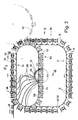
- the device shown as an exemplary embodiment in the drawings is particularly suitable for the treatment of cuboid packs 20 of the type soft cups for holding cigarettes.
- Packs 20 of this type consist of an inner wrapping - usually of tinfoil - for a cigarette group.
- the inner wrapper surrounds the cigarette group on all sides and thus forms a cigarette block 21.
- An outer wrapper usually consists of paper and is designed as a cup 22, that is to say open at the top.
- the top of the cigarette block 21 protrudes slightly from the cup 22.
- the pack formed in this way has, inter alia, an (upper) end face 23 and adjoining, opposing rectangular faces, namely front 24 and back 25.
- the package is therefore cuboid overall.
- a material strip or blank fastened by gluing extends over the end face 23, namely a (control) banderole 26. This lies with a middle region 27 on the end face 23.
- Legs 28, 29 extend in the area of front 24 and rear 25.
- the pack 20 has a plurality of glue connections, specifically in the area of overlapping folding flaps.
- the cup 22 is provided with folding tabs connected by adhesive, which are formed in the area of a base (opposite the end face 23) and / or in the area of a side face 30 or two opposite side faces 30.
- An important concern of the device is to enable the gluing of the pack 20 to be set while at the same time maintaining or stabilizing the cuboidal contour.
- the packs 20 are inserted into holders or pockets immediately after completion, that is to say with “fresh” glue spots, which correspond to the (cross-sectional) format of the packs 20 and therefore surround them in a form-fitting manner.
- the device is equipped with elongated, sleeve-shaped holders for the packs 20, namely with packing tubes 31, in each of which a larger number of packs 20 — in the exemplary embodiment shown (FIG. 6), three packs 20 each — are accommodated.
- the packing tubes 31 are open at both ends, so that the packing 20 can be inserted into the packing tube 31 in the longitudinal direction thereof at one end, namely via an insertion opening 32.
- a packing 20 simultaneously leaves the packing tube 31 via an outlet opening 33 as a result of the insertion process.
- the packs 20 are inserted with the end face 23 facing forward into the packing tube 31.
- This has a free internal cross section, which corresponds to the (smaller) cross section of the package 20.
- the side surfaces 30 of the pack 20 abut on side walls 34 of the pack tube 31.
- the end faces 23 are supported on floor surfaces 35 from adjacent packs 20 within the packing tube 31.
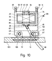
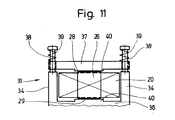
- FIG. 11 An advantageous embodiment for the cross-sectional design of the packing tube 31 results in particular from FIG. 11.
- a bottom wall 36 and the side walls 34 form a unit, namely a profile which is U-shaped in cross section.
- An upper wall 37 is designed as a separate element and is movably attached to the side walls 34.
- this is provided with (upright) support bolts 38, on which the top wall 37 is slidably mounted with corresponding bores.
- the top wall 37 is pressed with elastic pressure onto the upward-facing side of the packs 20, in the present case by compression springs 39 arranged on the support bolts 38. This exerts a shaping pressure on the packs 20 in the packing tube 31.
- Bottom wall 36 and top wall 37 do not lie against the packs 20 over their entire surface, but with web-like elevations 40. These extend in the central region of the pack tube 31, with a width that is greater than that of the (also central) band 26.
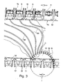
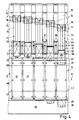
- a large number of drying tubes designed in this way are arranged on an endless conveyor next to one another in a parallel orientation and at a short distance from one another.
- the endless conveyor is an envelope conveyor, which runs over several, in this case four, deflection rollers (not shown).
- the resulting contour of a tube conveyor 41 with packing tubes 31 pointing transversely to the direction of movement results from FIG. 2.
- the packing tubes 31 are provided on their underside with connecting straps 46 for attachment to the toothed belts 42, 43. These have a bore 47 and at a distance from it an elongated hole 48. Ends of bearing bolts 49, 50 which are firmly connected to the toothed belt 42, 43 enter the elongated hole 48 or the bore 47 of the connecting straps 46.
- the bearing bolts 49, 50 are anchored in bead-shaped projections 51 on the facing or upper side of the toothed belt 42, 43 by embedding.
- the fully folded packs 20, which are glued in the area of the folding tabs, are fed directly from a folding turret 52 (or an appropriately designed intermediate conveyor).
- the packs 20 are then taken over by a pack conveyor 53, which is also designed here as an endless conveyor.
- the pack conveyor 53 runs in a plane offset from the tube conveyor 41.
- An upper conveying run 54 of the pack conveyor 53 and a receiving run 55 of the same length run synchronously with one another along a sufficient conveying path.
- the pack conveyor 53 is equipped with closely spaced pockets 57, each for receiving a pack.
- the pockets are attached to an elastic endless conveyor, namely a toothed belt 58.
- This is analogous to the embodiment of FIG. 11 with two spaced apart arranged and 59 molded on the top provided. Bearing bolts 60, 61 pass through these.
- At the ends of the webs 62 are supported, namely on the bearing pin 61 with an elongated hole 63.
- the webs 62 are in turn part of a pocket bottom 64 on which the pack 20 rests.
- the pack 20 is delimited laterally, namely in the region of the narrow side surfaces 30, by movable pocket walls 65. These are designed with corresponding extensions as two-armed, pivotable levers and each pivotable about a pivot bearing 66.
- the upper, free edges of the pocket walls 65 are formed with transverse holding legs 67, so that the packs 20 are hook-shaped on the upper or outer side.
- the pockets 57 are opened on the radially outer side by moving the pocket walls 65 apart.
- actuating arms 68 are acted upon appropriately in the region of the opening of the pockets 57.
- Support rollers 69 are attached to the ends of the actuating arms 68. These run on appropriately designed curved tracks (not shown), so that the pocket walls 65 are moved into the open position via the arc-shaped actuating arms 68. These are constantly loaded in the closed position by a tension spring 70 connecting the opposing pocket walls 65 to one another.
- each pocket 57 is assigned a slide 71 which rotates continuously with the assigned pocket 57.
- the slide consists of a slide plate 72, which grips the pack 20 on its bottom surface 35.
- An elongated slide rod 73 is connected to a slide 74, which is on a crossbar 75 is slidably mounted. This extends parallel to the movement path of the slide 71 or horizontally.
- the slider 71 is automatically controlled, in accordance with the conveying movement of the pocket 57 in the region of the transfer path 56.
- a guide pin 76 is attached to the slider 74, which engages in a fixed cam groove 77.
- the curved groove 77 is designed such that with continuous conveying movement of the pocket 57 with slide 71, the latter executes the extension movement, in such a way that the pack 20 arrives from the pocket 57 into an immediately opposite packing tube 31 of the tube conveyor 41.
- the slide 71 then returns to the starting position.
- the pack conveyor 53 is connected to a separate slide conveyor 78 to form a conveyor unit.
- a further endless conveyor namely a toothed belt 79, runs at a distance from the package conveyor 53 or its toothed belt 58. This is designed in a similar manner to the exemplary embodiments of toothed belts already described.
- Bearing pins 80 are held on the top in molded-on lugs.
- On the ends of the webs 81 connected to the cross member 75 are supported and fastened.
- the free end of the crossbeams 75 remote from the pack conveyor 53 is thus fastened to the toothed belt 79.
- the other end is connected to the pocket 57 and thereby to the timing belt 58 of the package conveyor 53.
- the unit formed in this way with two toothed belts 58, 79 is correspondingly moved continuously, synchronously with the tube conveyor 41.
- the pack 20 is provided with the band 26 in the region of the end face 23. This is kept ready at the insertion opening 32 in front of each packing tube 31, so that when the packing 20 is inserted into the packing tube 31, the band 26 lies in a U-shape over the end face 23 and adjacent packing surfaces.
- the packing tubes 31 are provided with chamfers 83 in the region of the insertion opening 32 on the bottom wall 36 and top wall 37.
- the insertion opening 32 acts here as a mouthpiece, which can also be designed in a different way, in particular does not have to be part of a packing tube. It is important, however, that several packs 20 are transported in succession in a sealed position, the end face 23 and the bottom surface 35 of adjacent packs 20 being mutually supportive.
- the band 26 is additionally fixed between the aforementioned pack surfaces of adjacent packs, so that undesired changes in position are avoided until the banding 26 is glued.
- the band 26 is kept in the upright position in front of the insertion opening 32 in the area of the transfer line 56.
- the band 26 lies against the end face of the packing tubes 31, namely on the bottom wall 36 on the one hand and the top wall 37 on the other hand, centrally to the insertion opening 32.
- suction bores 84, 85 open at the end faces of the bottom wall 36 and the top wall 37 in the region of the band 26.
- suction bores 84, 85 located at a distance from one another.
- Suction channels 86 adjoin these in the region of the top wall 37, side wall 34 and bottom wall 36 of the packing tube 31.
- a connection channel 87 runs in the bottom wall 36, which emerges from the bottom wall 36 and is connected to a flexible vacuum line 88, that is to say a hose.
- the packing tubes 31 are designed in the region of the insertion opening 32 as a rigid mouthpiece 106 which is closed in cross section.
- the suction channels 86 are also located in the area of this mouthpiece 106.
- the movable part of the upper wall 37 adjoins this mouthpiece 106.
- the rigid mouthpiece 106 results in a particularly precise shaping of the package 20 during the insertion movement.
- the banderole 26 is pressed and molded onto the package 20 with particular accuracy.
- the suction air or the vacuum is distributed via a central, common vacuum element.
- This consists of a suction disk 89 with suction connections 90 opening on its radial outer surface.
- the vacuum lines 88 are connected to these.
- the suction connections 90 are in turn connected to a distributor segment 91 in the region of a side surface of the suction disk 89. This is formed as an open groove in a fixed distributor disk 92.
- the distributor segment 91 is suitably connected to a vacuum source.
- the suction disc 89 is mounted on a shaft 93 driven in rotation.
- the suction disc 89 is driven synchronously with the (continuous) conveying movement of the packing tubes 31.
- the suction disc 89 is, as can be seen particularly in the center of FIG. 2, arranged within the area enclosed by the tube conveyor 41.
- the distributor segment 91 used to transmit the negative pressure extends in a partial area of the circumference of the suction disk 89 such that negative pressure is generated in the area of the suction bores 84, 85 during a partial section of the transfer path 56.
- the banderoles 26 are fed to the packing tubes 31 by a separate banderole conveyor 94.
- This is designed here as a banderole roller, which is driven to rotate continuously, namely in the same direction as the packing tubes 31.
- the band conveyor 94 is located in the region of an upright conveying path of the tube conveyor 41, namely in the region of a conveyor run 95.
- the band conveyor 94 is arranged in front of the end faces of the packing tubes 31 receiving the bands 26.
- the relative position is such that the circumferential surface of the banding roller leads to the end faces of the packing tubes 31, specifically in the area of the bottom wall 36 and top wall 37.
- the drum-shaped band conveyor 94 is provided with radially projecting, rib-like band carriers 96.
- the banderoles 26 lie against these with a central, strip-shaped region.
- a gluing unit 98 is assigned to the band conveyor 94. With this side glue surfaces or strips applied to the edge areas of the bands 26 for connection to the pack 20.
- the gluing unit 98 is provided with a roller-shaped glue application element 99, which takes the glue in strips from a glue container 100.
- the glue application member 99 each contains rib-like, radial projections 101, on the outside of which there is glue.
- the projections 101 are arranged in pairs, at a distance from one another which corresponds to the arrangement of glue strips on a band 26. These are moved on a conveyor roller 102 past the glue application member 99 such that the glue strips are transferred from the projections 101 to the outward-facing side of the banderoles 26.
- the banderoles are held on the conveyor roller 102 by suction air. Following this, the bands 26 provided with lateral adhesive strips are transferred to the band conveyor 24 or to a band carrier 96 of the same. The band 26 lies with an area between the glue strips on the band carrier 96.
- the glue strips are on the outside, so that they face the packing 20.
- the conveyors running parallel to each other for the organs assigned to them, namely toothed belts 42, 43 and 58, 79, are mounted on a common support member. It is a continuous machine plate 103 as part of a machine frame 104. In the machine plate 103, depressions 105 are formed in the area of the toothed belts in which the toothed belts run.
- the device is also suitable for processing packs in which a sleeve 26 cannot be attached.
- the organs required to keep the banderole ready and available are missing.
Landscapes
- Engineering & Computer Science (AREA)
- Mechanical Engineering (AREA)
- Labeling Devices (AREA)
- Auxiliary Devices For And Details Of Packaging Control (AREA)
- Wrapping Of Specific Fragile Articles (AREA)
- Making Paper Articles (AREA)
- Supplying Of Containers To The Packaging Station (AREA)
Applications Claiming Priority (2)
| Application Number | Priority Date | Filing Date | Title |
|---|---|---|---|
| DE4000685 | 1990-01-12 | ||
| DE4000685 | 1990-01-12 |
Publications (2)
| Publication Number | Publication Date |
|---|---|
| EP0437201A1 true EP0437201A1 (fr) | 1991-07-17 |
| EP0437201B1 EP0437201B1 (fr) | 1994-07-20 |
Family
ID=6397916
Family Applications (2)
| Application Number | Title | Priority Date | Filing Date |
|---|---|---|---|
| EP91100053A Expired - Lifetime EP0437201B1 (fr) | 1990-01-12 | 1991-01-02 | Dispositif de stabilisation de forme d'emballages (pour cigarettes) parallépipédiques |
| EP91100052A Expired - Lifetime EP0437200B1 (fr) | 1990-01-12 | 1991-01-02 | Dispositif pour la pose d'étiquettes et analogues sur des paquets |
Family Applications After (1)
| Application Number | Title | Priority Date | Filing Date |
|---|---|---|---|
| EP91100052A Expired - Lifetime EP0437200B1 (fr) | 1990-01-12 | 1991-01-02 | Dispositif pour la pose d'étiquettes et analogues sur des paquets |
Country Status (7)
| Country | Link |
|---|---|
| US (2) | US5129209A (fr) |
| EP (2) | EP0437201B1 (fr) |
| JP (2) | JP2768836B2 (fr) |
| CN (2) | CN1020691C (fr) |
| BR (2) | BR9100112A (fr) |
| CA (2) | CA2033683C (fr) |
| DE (3) | DE4042178C2 (fr) |
Cited By (4)
| Publication number | Priority date | Publication date | Assignee | Title |
|---|---|---|---|---|
| DE4037692A1 (de) * | 1990-11-27 | 1992-06-04 | Focke & Co | Vorrichtung zur formgebung und zum abbinden von leim quaderfoermiger (zigaretten-)packungen |
| WO1999003736A1 (fr) | 1997-07-15 | 1999-01-28 | Focke & Co. (Gmbh & Co.) | Procede et dispositif pour la manipulation de vignettes fiscales au cours de leur transfert sur des emballages, notamment de cigarettes |
| DE102012012204A1 (de) | 2012-06-21 | 2013-12-24 | Focke & Co. (Gmbh & Co. Kg) | Taschenförderer zum Fördern von Zigarettengruppen |
| EP2993140A1 (fr) | 2014-09-08 | 2016-03-09 | Focke & Co. (GmbH & Co. KG) | Procede et dispositif de stabilisation de forme d'emballages |
Families Citing this family (22)
| Publication number | Priority date | Publication date | Assignee | Title |
|---|---|---|---|---|
| DE4300149A1 (de) * | 1993-01-08 | 1994-07-14 | Focke & Co | Vorrichtung zum Herstellen von Zigaretten-Packungen |
| DE19616871A1 (de) * | 1996-04-26 | 1997-10-30 | Focke & Co | Verpackung für Tabakwaren, insbesondere Zigaretten sowie Verfahren und Vorrichtung zum Herstellen derselben |
| GB9713012D0 (en) * | 1997-06-19 | 1997-08-27 | Molins Plc | Package folding apparatus |
| IT1299323B1 (it) * | 1998-01-27 | 2000-03-16 | Gd Spa | Macchina condizionatrice per pacchetti di sigarette. |
| IT1299348B1 (it) * | 1998-02-13 | 2000-03-16 | Gd Spa | Metodo e macchina per l'incarto di un prodotto. |
| IT1299982B1 (it) * | 1998-04-22 | 2000-04-04 | Gd Spa | Metodo per la realizzazione di pacchetti di sigarette ed impianto per l'attuazione di tale metodo. |
| IT1309297B1 (it) * | 1999-06-22 | 2002-01-22 | Gd Spa | Convogliatore a tasche. |
| US6955033B2 (en) * | 2002-07-24 | 2005-10-18 | Hans-Joachim Lortz | Method of pushing tubular films onto elongate objects and processing apparatus for implementing the method |
| DE10158736A1 (de) * | 2001-11-30 | 2003-06-12 | Focke & Co | Verfahren und Vorrichtung zum Herstellen von Hartpackungen für Zigaretten |
| US6789370B2 (en) * | 2001-12-18 | 2004-09-14 | G.D Societa' Per Azioni | Cigarette packing machine |
| US6811640B2 (en) * | 2002-06-21 | 2004-11-02 | Quality Assured Enterprises, Inc. | Roll-to-roll method of creating extended text labels |
| TWI348450B (en) * | 2003-11-13 | 2011-09-11 | Applied Materials Inc | Break-away positioning conveyor mount for accommodating conveyor belt bends |
| DE102004009399A1 (de) * | 2004-02-24 | 2005-09-08 | Focke & Co.(Gmbh & Co. Kg) | Verfahren und Vorrichtung zum Herstellen von (Zigaretten-)Packungen |
| DE102011004976B4 (de) * | 2011-03-02 | 2023-09-07 | Krones Aktiengesellschaft | Etikettiervorrichtung und Etikettierverfahren |
| WO2016117635A1 (fr) * | 2015-01-21 | 2016-07-28 | 凸版印刷株式会社 | Dispositif de transport |
| DE102017102913A1 (de) * | 2017-02-14 | 2018-08-16 | Sig Technology Ag | Vorrichtung und Verfahren zur flexiblen Verteilung von Verpackungen |
| GB201821302D0 (en) * | 2018-12-31 | 2019-02-13 | British American Tobacco Investments Ltd | Apparatus and method for packaging tobacco industry products |
| BR112022013806A2 (pt) * | 2020-01-15 | 2022-09-13 | Philip Morris Products Sa | Método para formação de pares de maços |
| CN111907800B (zh) * | 2020-08-28 | 2022-09-30 | 湖北中烟工业有限责任公司 | 一种用于硬质条盒透明纸包装的曲面整形装置 |
| CN112537032B (zh) * | 2020-09-21 | 2024-05-14 | 中国人民解放军32181部队 | 数字标签自动化制作流水线及方法 |
| CN114408289B (zh) * | 2022-01-11 | 2025-03-14 | 温州市中轻五金刀具有限公司 | 一种胶带粘贴装置及其自动胶带泡壳贴卡机 |
| CN114392930B (zh) * | 2022-01-14 | 2023-05-16 | 浙江机电职业技术学院 | 一种轴承套圈滚道自动检测与分选装置及其使用方法 |
Citations (3)
| Publication number | Priority date | Publication date | Assignee | Title |
|---|---|---|---|---|
| FR2359032A1 (fr) * | 1976-07-22 | 1978-02-17 | Focke Pfuhl Verpack Automat | Procede et appareil pour le formage ou l'amelioration de la forme des paquets ou emballages en forme de parallelepipede rectangle |
| FR2409914A1 (fr) * | 1977-11-26 | 1979-06-22 | Hauni Werke Koerber & Co Kg | Dispositif pour apposer des etiquettes sur des emballages, notamment des bandes sur des paquets de cigarettes |
| GB2189429A (en) * | 1986-04-22 | 1987-10-28 | Focke & Co | Apparatus for the form-stabilizing storage of packs during glue hardening |
Family Cites Families (11)
| Publication number | Priority date | Publication date | Assignee | Title |
|---|---|---|---|---|
| DE1010907B (de) * | 1954-07-22 | 1957-06-19 | Rose Brothers Ltd | Zufuehrungsvorrichtung fuer Einwickelmaschinen, insbesondere fuer kleine Warenstuecke |
| US3236026A (en) * | 1962-08-01 | 1966-02-22 | Wix Of London Ltd | Apparatus for setting adhesive sealing means |
| JPS434799Y1 (fr) * | 1965-05-11 | 1968-02-29 | ||
| GB1168447A (en) * | 1965-10-12 | 1969-10-22 | Hauni Werke Koerber & Co Kg | Methods and Apparatus for Packaging Cigarettes and Other Rod-Like Articles |
| IT1005424B (it) * | 1974-01-24 | 1976-08-20 | Amf Sasib | Metodo e dispositivo per la forma zione degli involucri dei pacchet ti nelle macchine impacchettatrici di sigarette |
| JPS5162800U (fr) * | 1974-11-11 | 1976-05-18 | ||
| JPS5717913U (fr) * | 1980-06-30 | 1982-01-29 | ||
| DE3046065C2 (de) * | 1980-12-06 | 1984-11-29 | Maschinenfabrik Alfred Schmermund Gmbh & Co, 5820 Gevelsberg | Bodenfaltungspacker |
| IT1166432B (it) * | 1982-03-13 | 1987-04-29 | Molins Plc | Apparecchio per applicare etichette e simili su oggetti, in particolate pacchetti di sigarette |
| DE3400650A1 (de) * | 1984-01-11 | 1985-07-18 | Focke & Co, 2810 Verden | Verpackungsmaschine fuer packungen mit durch klebung verbundenen faltlappen |
| DE3815275A1 (de) * | 1988-05-05 | 1989-11-16 | Focke & Co | Verpackungsmaschine fuer klappschachteln |
-
1990
- 1990-12-29 DE DE4042178A patent/DE4042178C2/de not_active Expired - Fee Related
-
1991
- 1991-01-02 DE DE59102776T patent/DE59102776D1/de not_active Expired - Fee Related
- 1991-01-02 EP EP91100053A patent/EP0437201B1/fr not_active Expired - Lifetime
- 1991-01-02 DE DE59102204T patent/DE59102204D1/de not_active Expired - Fee Related
- 1991-01-02 EP EP91100052A patent/EP0437200B1/fr not_active Expired - Lifetime
- 1991-01-07 CA CA002033683A patent/CA2033683C/fr not_active Expired - Fee Related
- 1991-01-10 US US07/639,445 patent/US5129209A/en not_active Expired - Lifetime
- 1991-01-10 US US07/639,446 patent/US5121585A/en not_active Expired - Lifetime
- 1991-01-11 CA CA002034022A patent/CA2034022C/fr not_active Expired - Fee Related
- 1991-01-11 BR BR919100112A patent/BR9100112A/pt not_active IP Right Cessation
- 1991-01-11 BR BR919100118A patent/BR9100118A/pt not_active IP Right Cessation
- 1991-01-12 CN CN91100190A patent/CN1020691C/zh not_active Expired - Fee Related
- 1991-01-12 CN CN91100189A patent/CN1025314C/zh not_active Expired - Fee Related
- 1991-01-14 JP JP3002718A patent/JP2768836B2/ja not_active Expired - Fee Related
- 1991-01-14 JP JP3002723A patent/JP2768837B2/ja not_active Expired - Fee Related
Patent Citations (3)
| Publication number | Priority date | Publication date | Assignee | Title |
|---|---|---|---|---|
| FR2359032A1 (fr) * | 1976-07-22 | 1978-02-17 | Focke Pfuhl Verpack Automat | Procede et appareil pour le formage ou l'amelioration de la forme des paquets ou emballages en forme de parallelepipede rectangle |
| FR2409914A1 (fr) * | 1977-11-26 | 1979-06-22 | Hauni Werke Koerber & Co Kg | Dispositif pour apposer des etiquettes sur des emballages, notamment des bandes sur des paquets de cigarettes |
| GB2189429A (en) * | 1986-04-22 | 1987-10-28 | Focke & Co | Apparatus for the form-stabilizing storage of packs during glue hardening |
Cited By (8)
| Publication number | Priority date | Publication date | Assignee | Title |
|---|---|---|---|---|
| DE4037692A1 (de) * | 1990-11-27 | 1992-06-04 | Focke & Co | Vorrichtung zur formgebung und zum abbinden von leim quaderfoermiger (zigaretten-)packungen |
| WO1999003736A1 (fr) | 1997-07-15 | 1999-01-28 | Focke & Co. (Gmbh & Co.) | Procede et dispositif pour la manipulation de vignettes fiscales au cours de leur transfert sur des emballages, notamment de cigarettes |
| DE102012012204A1 (de) | 2012-06-21 | 2013-12-24 | Focke & Co. (Gmbh & Co. Kg) | Taschenförderer zum Fördern von Zigarettengruppen |
| WO2013189578A1 (fr) | 2012-06-21 | 2013-12-27 | Focke & Co. (Gmbh & Co. Kg) | Transporteur à poches destiné à transporter des groupes de cigarettes |
| CN104395195A (zh) * | 2012-06-21 | 2015-03-04 | 佛克有限及两合公司 | 用于输送香烟组的袋式输送机 |
| CN104395195B (zh) * | 2012-06-21 | 2016-06-15 | 佛克有限及两合公司 | 用于输送香烟组的袋式输送机 |
| EP2993140A1 (fr) | 2014-09-08 | 2016-03-09 | Focke & Co. (GmbH & Co. KG) | Procede et dispositif de stabilisation de forme d'emballages |
| DE102014012968A1 (de) | 2014-09-08 | 2016-03-10 | Focke & Co. (Gmbh & Co. Kg) | Verfahren und Vorrichtung zur Formstabilisierung von Packungen |
Also Published As
| Publication number | Publication date |
|---|---|
| DE4042178A1 (de) | 1991-09-19 |
| BR9100112A (pt) | 1991-10-22 |
| CN1053591A (zh) | 1991-08-07 |
| CA2033683A1 (fr) | 1991-07-13 |
| JPH04215931A (ja) | 1992-08-06 |
| EP0437201B1 (fr) | 1994-07-20 |
| US5121585A (en) | 1992-06-16 |
| CA2034022A1 (fr) | 1991-07-13 |
| JP2768836B2 (ja) | 1998-06-25 |
| EP0437200B1 (fr) | 1994-09-07 |
| US5129209A (en) | 1992-07-14 |
| JP2768837B2 (ja) | 1998-06-25 |
| BR9100118A (pt) | 1991-10-22 |
| EP0437200A1 (fr) | 1991-07-17 |
| CA2034022C (fr) | 2000-08-15 |
| CN1025314C (zh) | 1994-07-06 |
| DE59102776D1 (de) | 1994-10-13 |
| JPH04215911A (ja) | 1992-08-06 |
| CA2033683C (fr) | 2001-05-01 |
| DE59102204D1 (de) | 1994-08-25 |
| DE4042178C2 (de) | 2002-04-25 |
| CN1054042A (zh) | 1991-08-28 |
| CN1020691C (zh) | 1993-05-19 |
Similar Documents
| Publication | Publication Date | Title |
|---|---|---|
| EP0437201B1 (fr) | Dispositif de stabilisation de forme d'emballages (pour cigarettes) parallépipédiques | |
| EP0605838B1 (fr) | Dispositif pour la fabrication de paquets de cigarettes | |
| EP0197368B1 (fr) | Procédé et dispositif pour l'empaquetage, en particulier de cigarettes | |
| DE3802644C2 (de) | Verfahren und Vorrichtung zum Herstellen von Klappschachteln für Zigaretten | |
| EP0243757B1 (fr) | Machine d'emballage pour emballages avec volets de pliage reliés par collage | |
| EP0275886B1 (fr) | Machine d'emballage avec revolver de séchage | |
| EP0386524A1 (fr) | Dispositif d'emballage d'objets de différentes dimensions | |
| EP1829783B1 (fr) | Dispositif et procédé de fabrication d'emballages doubles | |
| EP0564988A2 (fr) | Procédé et dispositif pour le transport d'emballages | |
| DE2440006A1 (de) | Verfahren und vorrichtung zum herstellen und fuellen von klappschachteln aus faltbarem werkstoff, vorzugsweise fuer zigaretten | |
| DE2810586A1 (de) | Verfahren und vorrichtung zum einfuehren von insbesondere zigarettengruppen in eine zigarettenpackung | |
| DE3739551A1 (de) | Vorrichtung zum transport von zigaretten-packungen im zusammenhang mit einer verpackungsmaschine | |
| EP0034790B1 (fr) | Installation pour appliquer des banderoles autour de paquets de cigarettes carrés | |
| DE69802165T2 (de) | Verfahren und vorrichtung zum anbringen von lösbaren etiketten auf annähernd quaderförmigen verpackungen | |
| DE1980633U (de) | Zigaretten-verpackungsmaschine. | |
| DE2752819A1 (de) | Vorrichtung zum aufbringen von etiketten auf verpackungen, insbesondere von banderolen auf zigarettenpackungen | |
| DE2315338A1 (de) | Foerdervorrichtung in einer packmaschine zum verpacken von stabfoermigen artikeln der tabakverarbeitenden industrie | |
| DE10203459A1 (de) | Verfahren und Vorrichtung zum Herstellen von Gebindepackung für Zigaretten | |
| EP0418687B1 (fr) | Machine d'emballage pour pliage des extrémités de l'enveloppe | |
| DE2328564A1 (de) | Packmaschine fuer zigaretten oder andere gegenstaende | |
| WO2011047745A1 (fr) | Dispositif de stockage de paquets (de cigarettes) | |
| DE4042179A1 (de) | Vorrichtung zur formstabilisierung quaderfoermiger (zigaretten-) packungen | |
| EP0233470B1 (fr) | Dispositif pour stocker des paquets (de cigarettes) | |
| EP1809537B1 (fr) | Dispositif pour envelopper des groupes de paquets | |
| DE2454289A1 (de) | Verpackungsvorrichtung |
Legal Events
| Date | Code | Title | Description |
|---|---|---|---|
| PUAI | Public reference made under article 153(3) epc to a published international application that has entered the european phase |
Free format text: ORIGINAL CODE: 0009012 |
|
| AK | Designated contracting states |
Kind code of ref document: A1 Designated state(s): DE FR GB IT |
|
| 17P | Request for examination filed |
Effective date: 19911129 |
|
| 17Q | First examination report despatched |
Effective date: 19930608 |
|
| GRAA | (expected) grant |
Free format text: ORIGINAL CODE: 0009210 |
|
| AK | Designated contracting states |
Kind code of ref document: B1 Designated state(s): DE FR GB IT |
|
| GBT | Gb: translation of ep patent filed (gb section 77(6)(a)/1977) |
Effective date: 19940719 |
|
| REF | Corresponds to: |
Ref document number: 59102204 Country of ref document: DE Date of ref document: 19940825 |
|
| ITF | It: translation for a ep patent filed | ||
| ET | Fr: translation filed | ||
| PLBE | No opposition filed within time limit |
Free format text: ORIGINAL CODE: 0009261 |
|
| STAA | Information on the status of an ep patent application or granted ep patent |
Free format text: STATUS: NO OPPOSITION FILED WITHIN TIME LIMIT |
|
| 26N | No opposition filed | ||
| REG | Reference to a national code |
Ref country code: GB Ref legal event code: IF02 |
|
| PGFP | Annual fee paid to national office [announced via postgrant information from national office to epo] |
Ref country code: GB Payment date: 20080102 Year of fee payment: 18 |
|
| PGFP | Annual fee paid to national office [announced via postgrant information from national office to epo] |
Ref country code: FR Payment date: 20080108 Year of fee payment: 18 |
|
| PGFP | Annual fee paid to national office [announced via postgrant information from national office to epo] |
Ref country code: DE Payment date: 20090121 Year of fee payment: 19 |
|
| PGFP | Annual fee paid to national office [announced via postgrant information from national office to epo] |
Ref country code: IT Payment date: 20090127 Year of fee payment: 19 |
|
| GBPC | Gb: european patent ceased through non-payment of renewal fee |
Effective date: 20090102 |
|
| REG | Reference to a national code |
Ref country code: FR Ref legal event code: ST Effective date: 20091030 |
|
| PG25 | Lapsed in a contracting state [announced via postgrant information from national office to epo] |
Ref country code: GB Free format text: LAPSE BECAUSE OF NON-PAYMENT OF DUE FEES Effective date: 20090102 |
|
| PG25 | Lapsed in a contracting state [announced via postgrant information from national office to epo] |
Ref country code: FR Free format text: LAPSE BECAUSE OF NON-PAYMENT OF DUE FEES Effective date: 20090202 |
|
| PG25 | Lapsed in a contracting state [announced via postgrant information from national office to epo] |
Ref country code: DE Free format text: LAPSE BECAUSE OF NON-PAYMENT OF DUE FEES Effective date: 20100803 |
|
| PG25 | Lapsed in a contracting state [announced via postgrant information from national office to epo] |
Ref country code: IT Free format text: LAPSE BECAUSE OF NON-PAYMENT OF DUE FEES Effective date: 20100102 |