EP0437497B1 - Viseur pour appareil photographique - Google Patents
Viseur pour appareil photographique Download PDFInfo
- Publication number
- EP0437497B1 EP0437497B1 EP89911507A EP89911507A EP0437497B1 EP 0437497 B1 EP0437497 B1 EP 0437497B1 EP 89911507 A EP89911507 A EP 89911507A EP 89911507 A EP89911507 A EP 89911507A EP 0437497 B1 EP0437497 B1 EP 0437497B1
- Authority
- EP
- European Patent Office
- Prior art keywords
- frame
- frames
- lens
- optical path
- cam
- Prior art date
- Legal status (The legal status is an assumption and is not a legal conclusion. Google has not performed a legal analysis and makes no representation as to the accuracy of the status listed.)
- Expired - Lifetime
Links
Images


Classifications
-
- G—PHYSICS
- G03—PHOTOGRAPHY; CINEMATOGRAPHY; ANALOGOUS TECHNIQUES USING WAVES OTHER THAN OPTICAL WAVES; ELECTROGRAPHY; HOLOGRAPHY
- G03B—APPARATUS OR ARRANGEMENTS FOR TAKING PHOTOGRAPHS OR FOR PROJECTING OR VIEWING THEM; APPARATUS OR ARRANGEMENTS EMPLOYING ANALOGOUS TECHNIQUES USING WAVES OTHER THAN OPTICAL WAVES; ACCESSORIES THEREFOR
- G03B13/00—Viewfinders; Focusing aids for cameras; Means for focusing for cameras; Autofocus systems for cameras
- G03B13/02—Viewfinders
- G03B13/10—Viewfinders adjusting viewfinders field
- G03B13/12—Viewfinders adjusting viewfinders field to compensate for change of camera lens or size of picture
Definitions
- the present invention relates to view finder devices for use in cameras and more particularly to an improved view finder device in which a plurality of lenses can be selectively positioned in a viewing position or optical path.
- Mechanisms are know which change the magnification of a view finder in cameras having more than one photographic lens and in cameras for producing special effects such as pseudo tele or pseudo pan.
- Such mechanisms are complicated and capable of providing only two levels of magnification.
- the patent US-E-0 030 231 shows a device for placing any one of three or more lenses in an optical path.
- the lenses are shifted between retracted and operative positions by a plurality of drive means, each being coupled to a respective lens assembly and there being one less drive means than there are lens assemblies.
- Follower means engaging that lens assembly which is not coupled to position it in the optical path.
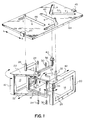
- FIG. 1 there is shown a view finder device for a photographic camera.
- camera parts not necessary for an understanding of the invention have been omitted.
- the eye lens and front element are not shown and the disclosure is limited to apparatus for moving the movable lens element.
- FIG. 1 of the drawings there is shown a view finder comprising three lenses 10, 12 and 14 mounted in frames 16, 18 and 20 respectively.
- lens 10 might be the normal view finder lens.
- Lens 12 might be used to provide magnification of the scene in the view finder for pseudo tele purposes and lens 20 might be used to provide panoramic views for pseudo pan purposes.
- Frame 16 is of rectangular configuration and comprises a pair of flanges 22 extending from one side thereof which are pivotaly mounted on pins 24 fixed to the camera body (not shown).
- a third pin 26 extends from the upper flange 22 and functions as a cam pin for pivoting the frame about the axis of pins 24 as will later be described in more detail.
- Frame 20 positioned in spaced parallel relationship with frame 16, is similar in configuration to frame 16 and includes a pair of flanges 28 pivotally mounted on a pair of pins 30 fixed to the camera body.
- a cam pin 32 extends upward from the upper flange 28 and provides a means for pivoting the frame 16 about the axis of pins 30, an axis parallel to the axis of pins 24.
- the third frame 18, positioned in perpendicular relationship with frames 16 and 20, is also similarly configured and provided with a pair of spaced flanges 34 pivotally mounted on a pair of pins 36 fixed to the camera body.
- the frame 18 is positioned between the flanges 22 and 28 and pivots about the horizontal axis of pins 36 which axis is perpendicular to that of pins 24 and that of pins 30.
- An elongated cam arm 38 extending perpendicularly from the plane of frame 18 and pivotally connected to frame 18 by pin 39 is provided with an upwardly extending pin 40 at its end to provide a means for pivoting the frame 18 about the axis of pins 36.
- the lens 12 is positioned in the sight plane 42 and is the operative lens.
- a cam plate 44 is positioned over the frame assemblage and suitably supported in guides 45 for rectilinear reciprocal movement in the direction of the arrow.
- the cam plate 44 is provided with three slots 46, 48 and 50.
- Pin 26 of frame 16 is received by slot 46, pin 40 of frame 18 by slot 50 and pin 32 of frame 20 by slot 48. Movement of the plate 44 to the right and left from the position shown in FIG. 1 will position the frame 18 out of the optical path and position one of the frames into the optical path depending upon the direction of movement as will now be described.
- pin 40 will be cammed by portion (b) of slot 50 to again pivot frame 18 out of the optical path.
- pin 26 will ride in the straight portion (b) of slot 46 and no movement of frame 16 will occur.
- pin 32 of frame 20 will be cammed by portion (a) of slot 48 to position frame 20 in the optical path as shown in FIG. 3.
- the disclosed view finder device thus constitutes a simple compact device for selectively positioning at least three lenses in a optical path.
Landscapes
- Physics & Mathematics (AREA)
- General Physics & Mathematics (AREA)
- Viewfinders (AREA)
- Structure And Mechanism Of Cameras (AREA)
Abstract
Claims (5)
- Dispositif pour disposer à volonté l'une de trois lentilles (10, 12, 14) sur un trajet optique, dispositif comprenant :
un premier, un second et un troisième barillet (16, 18, 20), chacun étant agencé pour supporter une lentille et étant monté de manière à se déplacer entre une première position dans laquelle le barillet est situé hors du trajet optique et une seconde position dans laquelle le barillet est situé sur le trajet optique, les barillets (16, 18, 20) étant montés de manière que, lorsqu'ils occupent leurs secondes positions, ils sont situés dans des plans pratiquement parallèles les uns aux autres, et
des moyens (26, 32, 40, 44) pour déplacer à volonté lesdits barillets (16, 18, 20) entre leur première et leur seconde position de telle sorte que seulement un des barillets puisse être, à un instant donné, placé dans une seconde position ;
ledit dispositif étant caractérisé en ce que :
chaque barillet est monté de manière à pouvoir basculer entre ladite première position et ladite seconde position autour d'un axe parallèle au plan du barillet, les axes de basculement dudit premier barillet (16) et dudit second barillet (20) étant parallèle l'un à l'autre et étant orthogonal à l'axe de basculement dudit troisième barillet (18) ; et
les moyens pour déplacer lesdits barillets comprennent d'une part, des premiers (26), des seconds (32) et des troisièmes (20) éléments de came qui sont reliés respectivement audit premier (16), second (20) et troisième (18) barillet et d'autre part, une autre came (44) mobile par translation et présentant des fentes guides venant en prise simultanément avec lesdits premiers (26), lesdits seconds (32) et lesdits troisièmes éléments de came (40) de manière que la position de ladite autre came (44) mobile par translation détermine la position occupée par lesdits barillets. - Dispositif selon la revendication 1, caractérisé en ce que les premiers (26) et les seconds (32) éléments de came comprennent un ergot débordant directement et respectivement le premier (16) et le second (20) barillet et les troisièmes éléments de came (40) comprennent un bras (38) qui est muni d'un ergot à l'une de ses extrémités et qui est articulé à l'autre extrémité sur ledit troisième barillet (18).
- Dispositif selon la revendication 1 ou 2, caractérisé en ce que ladite autre came mobile par translation comprend une plaque munie de trois fentes guides (46, 48, 50), chacune étant en prise avec l'un des premiers, seconds et troisièmes éléments de came.
- Dispositif selon la revendication 3, dans lequel ladite plaque (44) est mobile, à partir d'une position médiane dans laquelle le troisième barillet (18) est disposé sur le trajet optique, dans une première direction vers une seconde position dans laquelle ledit second barillet (20) est disposé sur le trajet optique ou dans une seconde direction, éloignée de la position médiane, dans laquelle ledit premier barillet (16) est disposé sur le trajet optique.
- Dispositif selon la revendication 4, dans laquelle, lorsque les premier et second barillets (16, 20) sont dans leur première position, ils sont parallèles entre eux et ledit troisième barillet (18) est située entre eux dans un plan orthogonal aux plan des premier et second barillet.
Applications Claiming Priority (3)
| Application Number | Priority Date | Filing Date | Title |
|---|---|---|---|
| US25509188A | 1988-10-07 | 1988-10-07 | |
| US255091 | 1988-10-07 | ||
| PCT/US1989/004342 WO1990004197A1 (fr) | 1988-10-07 | 1989-10-04 | Viseur pour appareil photographique |
Publications (2)
| Publication Number | Publication Date |
|---|---|
| EP0437497A1 EP0437497A1 (fr) | 1991-07-24 |
| EP0437497B1 true EP0437497B1 (fr) | 1994-05-04 |
Family
ID=22966803
Family Applications (2)
| Application Number | Title | Priority Date | Filing Date |
|---|---|---|---|
| EP89911507A Expired - Lifetime EP0437497B1 (fr) | 1988-10-07 | 1989-10-04 | Viseur pour appareil photographique |
| EP89118641A Withdrawn EP0363850A1 (fr) | 1988-10-07 | 1989-10-06 | Viseur pour caméra |
Family Applications After (1)
| Application Number | Title | Priority Date | Filing Date |
|---|---|---|---|
| EP89118641A Withdrawn EP0363850A1 (fr) | 1988-10-07 | 1989-10-06 | Viseur pour caméra |
Country Status (6)
| Country | Link |
|---|---|
| EP (2) | EP0437497B1 (fr) |
| JP (1) | JPH04501015A (fr) |
| DE (1) | DE68915174T2 (fr) |
| HK (1) | HK125194A (fr) |
| MY (1) | MY105068A (fr) |
| WO (1) | WO1990004197A1 (fr) |
Families Citing this family (1)
| Publication number | Priority date | Publication date | Assignee | Title |
|---|---|---|---|---|
| EP2485920B1 (fr) | 2009-10-08 | 2016-04-27 | Merck Sharp & Dohme Corp. | Composés hétérocycliques iminopentafluorosoufrés en tant qu'inhibiteurs de bace-1, compositions et leur utilisation |
Citations (1)
| Publication number | Priority date | Publication date | Assignee | Title |
|---|---|---|---|---|
| USRE30231E (en) * | 1973-12-22 | 1980-03-18 | Minolta Camera Kabushiki Kaisha | Lens selection device |
Family Cites Families (5)
| Publication number | Priority date | Publication date | Assignee | Title |
|---|---|---|---|---|
| US3124682A (en) * | 1964-03-10 | Microscope system for use with both | ||
| DE2558276A1 (de) * | 1975-12-23 | 1977-07-07 | Agfa Gevaert Ag | Fotografische kamera |
| US4264175A (en) * | 1979-07-18 | 1981-04-28 | West Electric Company, Ltd. | Focusing device in camera equipped with both standard and telephoto lenses |
| GB2152229B (en) * | 1983-11-30 | 1987-01-14 | Mitutoyo Mfg Co Ltd | Microscope |
| US4690531A (en) * | 1985-06-24 | 1987-09-01 | Eastman Kodak Company | Low cost telephoto and normal lens camera with an extendable flash |
-
1989
- 1989-10-04 WO PCT/US1989/004342 patent/WO1990004197A1/fr not_active Ceased
- 1989-10-04 EP EP89911507A patent/EP0437497B1/fr not_active Expired - Lifetime
- 1989-10-04 DE DE68915174T patent/DE68915174T2/de not_active Expired - Fee Related
- 1989-10-04 JP JP1510710A patent/JPH04501015A/ja active Pending
- 1989-10-06 MY MYPI89001373A patent/MY105068A/en unknown
- 1989-10-06 EP EP89118641A patent/EP0363850A1/fr not_active Withdrawn
-
1994
- 1994-11-10 HK HK125194A patent/HK125194A/en unknown
Patent Citations (1)
| Publication number | Priority date | Publication date | Assignee | Title |
|---|---|---|---|---|
| USRE30231E (en) * | 1973-12-22 | 1980-03-18 | Minolta Camera Kabushiki Kaisha | Lens selection device |
Also Published As
| Publication number | Publication date |
|---|---|
| DE68915174T2 (de) | 1994-11-17 |
| MY105068A (en) | 1994-07-30 |
| EP0363850A1 (fr) | 1990-04-18 |
| DE68915174D1 (de) | 1994-06-09 |
| JPH04501015A (ja) | 1992-02-20 |
| WO1990004197A1 (fr) | 1990-04-19 |
| HK125194A (en) | 1994-11-18 |
| EP0437497A1 (fr) | 1991-07-24 |
Similar Documents
| Publication | Publication Date | Title |
|---|---|---|
| US5778268A (en) | Stereo camera | |
| US4725863A (en) | Stereo camera | |
| US4464028A (en) | Motion picture system for single strip 3-D filming | |
| US4609270A (en) | Camera with interchangeable taking lenses | |
| JPH10254055A (ja) | 多焦点カメラ | |
| US5345287A (en) | Apparatus for correcting parallax and/or diopter of camera | |
| US4931818A (en) | Camera view finder | |
| EP0325140B1 (fr) | Caméra à deux objectifs | |
| EP0437497B1 (fr) | Viseur pour appareil photographique | |
| US5708867A (en) | Interconnection mechanism for zoom camera | |
| EP0437507B1 (fr) | Viseur pour appareil photographique | |
| JP2000056412A (ja) | 立体画像撮影用アタッチメント | |
| US4983997A (en) | Microphotographic apparatus with automatic film format reflection | |
| US4146315A (en) | Lens moving device for opaque reader | |
| US4136939A (en) | Rangefinding optical system | |
| US3720462A (en) | Microfiche film reader | |
| US5732301A (en) | Camera having variable-sized image plane and image plane size indicator | |
| US4990946A (en) | Viewfinder | |
| US3150579A (en) | Camera bright-frame viewfinder with coupled rangefinder | |
| US5500704A (en) | Apparatus for partially intercepting light in finder of camera | |
| KR100251250B1 (ko) | 포토비디오카메라장치 | |
| KR19980015490A (ko) | 스테레오 카메라 | |
| JPH0325423A (ja) | カメラのファインダー | |
| JPH03267928A (ja) | カメラのファインダー | |
| JPH0862672A (ja) | 実像式ファインダ |
Legal Events
| Date | Code | Title | Description |
|---|---|---|---|
| PUAI | Public reference made under article 153(3) epc to a published international application that has entered the european phase |
Free format text: ORIGINAL CODE: 0009012 |
|
| 17P | Request for examination filed |
Effective date: 19910404 |
|
| AK | Designated contracting states |
Kind code of ref document: A1 Designated state(s): BE CH DE FR GB IT LI NL SE |
|
| 17Q | First examination report despatched |
Effective date: 19930819 |
|
| GRAA | (expected) grant |
Free format text: ORIGINAL CODE: 0009210 |
|
| AK | Designated contracting states |
Kind code of ref document: B1 Designated state(s): DE FR GB |
|
| REF | Corresponds to: |
Ref document number: 68915174 Country of ref document: DE Date of ref document: 19940609 |
|
| ET | Fr: translation filed | ||
| PLBE | No opposition filed within time limit |
Free format text: ORIGINAL CODE: 0009261 |
|
| STAA | Information on the status of an ep patent application or granted ep patent |
Free format text: STATUS: NO OPPOSITION FILED WITHIN TIME LIMIT |
|
| 26N | No opposition filed | ||
| PGFP | Annual fee paid to national office [announced via postgrant information from national office to epo] |
Ref country code: GB Payment date: 19950914 Year of fee payment: 7 |
|
| PGFP | Annual fee paid to national office [announced via postgrant information from national office to epo] |
Ref country code: FR Payment date: 19951009 Year of fee payment: 7 |
|
| PGFP | Annual fee paid to national office [announced via postgrant information from national office to epo] |
Ref country code: DE Payment date: 19951026 Year of fee payment: 7 |
|
| PG25 | Lapsed in a contracting state [announced via postgrant information from national office to epo] |
Ref country code: GB Effective date: 19961004 |
|
| GBPC | Gb: european patent ceased through non-payment of renewal fee |
Effective date: 19961004 |
|
| PG25 | Lapsed in a contracting state [announced via postgrant information from national office to epo] |
Ref country code: FR Effective date: 19970630 |
|
| PG25 | Lapsed in a contracting state [announced via postgrant information from national office to epo] |
Ref country code: DE Effective date: 19970701 |
|
| REG | Reference to a national code |
Ref country code: FR Ref legal event code: ST |