EP0438032A2 - Bateau avec porte d'étrave - Google Patents
Bateau avec porte d'étrave Download PDFInfo
- Publication number
- EP0438032A2 EP0438032A2 EP90811019A EP90811019A EP0438032A2 EP 0438032 A2 EP0438032 A2 EP 0438032A2 EP 90811019 A EP90811019 A EP 90811019A EP 90811019 A EP90811019 A EP 90811019A EP 0438032 A2 EP0438032 A2 EP 0438032A2
- Authority
- EP
- European Patent Office
- Prior art keywords
- boat
- flap
- bow
- wall
- water
- Prior art date
- Legal status (The legal status is an assumption and is not a legal conclusion. Google has not performed a legal analysis and makes no representation as to the accuracy of the status listed.)
- Granted
Links
- XLYOFNOQVPJJNP-UHFFFAOYSA-N water Substances O XLYOFNOQVPJJNP-UHFFFAOYSA-N 0.000 claims abstract description 37
- 230000007704 transition Effects 0.000 claims description 14
- 230000000694 effects Effects 0.000 claims description 3
- 238000011084 recovery Methods 0.000 abstract description 3
- 230000001771 impaired effect Effects 0.000 abstract description 2
- 101001017827 Mus musculus Leucine-rich repeat flightless-interacting protein 1 Proteins 0.000 description 32
- 238000003287 bathing Methods 0.000 description 2
- 230000009189 diving Effects 0.000 description 2
- 238000007789 sealing Methods 0.000 description 2
- 230000006378 damage Effects 0.000 description 1
- 230000005484 gravity Effects 0.000 description 1
- 238000007654 immersion Methods 0.000 description 1
- 239000012535 impurity Substances 0.000 description 1
- 238000000034 method Methods 0.000 description 1
- 230000002787 reinforcement Effects 0.000 description 1
- 239000004576 sand Substances 0.000 description 1
- 230000000087 stabilizing effect Effects 0.000 description 1
Images

Classifications
-
- B—PERFORMING OPERATIONS; TRANSPORTING
- B63—SHIPS OR OTHER WATERBORNE VESSELS; RELATED EQUIPMENT
- B63B—SHIPS OR OTHER WATERBORNE VESSELS; EQUIPMENT FOR SHIPPING
- B63B19/00—Arrangements or adaptations of ports, doors, windows, port-holes, or other openings or covers
- B63B19/08—Ports or like openings in vessels' sides or at the vessels' bow or stern
-
- B—PERFORMING OPERATIONS; TRANSPORTING
- B63—SHIPS OR OTHER WATERBORNE VESSELS; RELATED EQUIPMENT
- B63B—SHIPS OR OTHER WATERBORNE VESSELS; EQUIPMENT FOR SHIPPING
- B63B27/00—Arrangement of ship-based loading or unloading equipment for cargo or passengers
- B63B27/14—Arrangement of ship-based loading or unloading equipment for cargo or passengers of ramps, gangways or outboard ladders ; Pilot lifts
- B63B27/143—Ramps
-
- B—PERFORMING OPERATIONS; TRANSPORTING
- B63—SHIPS OR OTHER WATERBORNE VESSELS; RELATED EQUIPMENT
- B63B—SHIPS OR OTHER WATERBORNE VESSELS; EQUIPMENT FOR SHIPPING
- B63B19/00—Arrangements or adaptations of ports, doors, windows, port-holes, or other openings or covers
- B63B19/08—Ports or like openings in vessels' sides or at the vessels' bow or stern
- B63B2019/083—Bow ports, e.g. for ferries
Definitions
- the invention relates to a boat according to the preamble of claim 1.
- Boats of this type are to be distinguished from those in which a flat flap, such as. B. are arranged in DE-OS 2 029 165 by means of a hinge in a flat boat wall part. Those boats have the disadvantage of hydrodynamically unfavorable driving behavior.
- a boat of the type mentioned is known from FR-A 2 511 969. With this boat as well as with other boats, care is taken that the flap is always close to the boat wall when swiveling.
- the flap lower part has a recess into which the lower edge of the bow opening engages in a sealing manner when unfolding.
- the shape of the bow portion below the flap opening is adapted to the pivoting movement of the flap about its pivot axis, ie it is designed as a family of partial circles with a center point on the pivot axis. The one below the fuselage part of the bow opening can therefore no longer be adapted to optimal flow conditions.
- the object of the invention is to provide a boat with a bow flap which has good driving properties both when the bow flap is open and when it is closed.
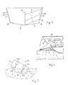
- the boat shown in Figure 1 in a side view has in its spoon-shaped as shown in Figure 2 or V-, in the longitudinal direction of the boat convex bow a flap 1 arranged symmetrically to the center line of the boat, which is shown unfolded in FIGS. 3 and 4 , its outer wall 3 being partially immersed in water 4 .
- the outer wall 3 of the flap 1 is also curved like a spoon and is designed such that its outer shape continues aerodynamically and hydrodynamically into the outer front wall 7 when closed. Through this design it acts by partial immersion into water 4 as a anströmbares plate with good hydrodynamic properties so that it can be driven with the unfolded, partly submerged into the water valve 1, the valve 1 then raises the bow.
- An intermediate space 2 is present between the lower flap part of the opened flap 1 and the front wall part located under the bow opening 15 . Through this space 2 , air is sucked under the hull, which on the one hand prevents the ingress of water 4 and on the other hand reduces the sliding friction of the hull.
- the open flap 1 also generates additional buoyancy for the boat through its shape and through a closed cavity 6 located between the outer and inner flap walls, shown in FIG. 4 in section through the flap 1 .
- the rubbing strake 8a of the boat is also continued in the flap 1 , and serves here as a butt edge 8b and flap reinforcement. If the flap 1 is used as a loading flap or landing flap, as described below, the abutting edge 8a is changed according to its intended use compared to the embodiment shown in FIGS. 2 and 3 .
- the flap 1 has on its inside on both sides a shoulder 9a and 9b parallel to the boat axis.
- Each attachment 9a or 9b has a bracket 11 directed towards the boat bottom 10 , via which the flap 1 is articulated directly on a swivel joint 13a and 13b on the inside of the boat in the vicinity of the bow opening 15 is stored above the boat bottom 10 .
- the flap pivot axis with respect to which the bow opening 15 enclosing Bugwandrand 17 set back towards a distance from the boat center.
- Each boom 11 has between its swivel 13a and 13b a downwardly open recess 19a and 19b , into which the boat bottom edge 21 delimiting the flap opening 15 engages when the flap 1 is pivoted downward.
- a double-acting piston cylinder unit 23a or 23b ie exerting tension and pressure, is mounted on a bearing 22a or 22b of the shoulder 9a or 9b .
- the base point 25a or 25b of the piston cylinder unit 23a or 23b is pivotably mounted at approximately the same height as the piston bearing on the inside of the boat.
- electromechanical adjustment devices can also be used.
- the flap 1 has a cavity 6 on the inside in order to achieve additional buoyancy when the flap 1 is partially pushed into the water with the piston-cylinder units 23a and 23b , which, as described below, is of great use in diving work, bathing operations or the like . This also pushes the bow up and can therefore be subjected to additional loads.
- the buoyancy is so great that one or two people can easily stand on the open flap 1 without impairing the stability of the boat.
- the flap 1 is arranged and mounted so that it can be pivoted into a position in which the outside of the outer wall 3 of the flap 1 is almost completely below and the inside is approximately at the level of the water line.
- the boat outer floor 35 has an angular transition 36 to the boat outer side wall 37 and a round transition 39 in its rear part.
- the angular transition 36 merges with the shoulder 41 located approximately in the middle of the length of the boat into the round transition 39 .
- paragraph 41 can be arranged at a distance of two thirds of the total length of the boat from the bow of the boat.
- the boat profile and in particular the round and angular transition 36 and 39 are shown in FIG. 5 . Since the boat profile runs symmetrically to the center line 40 , only one half of the profile is always shown in order not to overload the illustration, the profiles with an angular transition 36 being shown on the right-hand side in FIG. 5 and the round transitions on the left-hand side.
- the letters A to G denote the profile locations, as indicated in the side view of the boat in Figure 1 .
- the center of gravity of the boat is very low, which contributes to the capsizing safety mentioned below.
- the arrangement of the angular and round transition 36 and 39 described above has proven particularly useful when driving curves 44 on the water of a boat 46 equipped with two stern motors 45a and 45b , as shown in FIGS. 6 and 7 .
- the angular transition 36 Through the angular transition 36 , the water is channeled under the boat bottom 35 parallel to the longitudinal axis of the boat.
- the boat leans 46 As shown in Figure 7, the curve center.
- the water 4 as represented by two schematic flow lines 47a and 47b , is directed in the bow-side part of the boat 46 up to the heel 41 parallel to the boat axis and immediately bends outward behind the heel 41 under the boat 46 .
- paragraphs 41 are drawn to the side in FIG. 6 for better identification.
- water 4 is led up to the drive screw 48a of the stern motor 45a raised on the left in a right turn, whereupon the latter remains completely in the water and can continue to deliver its full thrust into the water.
- the round transition 39 Due to the round transition 39 , the boat glides away slightly in the curve 44 with its stern, as a result of which its curve radius is considerably reduced.
- this design of the boat hull an extremely precise approach to a desired location in a body of water is possible to then at this location with the flap 1 z. B. to carry out rescue work, to take bathers, to drop divers and to drive near the beach or shore in order to be able to get out easily.
- the piston-cylinder units 23a and 23b are set to thrust by means of a control valve (not shown), as a result of which the flap part 5 is moved out of the bow against the water surface.
- the flap 1 can be continuously adjusted and fixed in any angular position via the piston-cylinder units 23a and 23b .
- the lowest pivot point of the flap 1 is reached when the abutting edge 8b is just above the water line as the upper flap edge.
- the outer flap wall 3 is almost completely in the water 4 . Since the flap outer wall 3 is arched like a spoon and its two sides are closed by the shoulders 9a and 9b , the flap 1 pressed into the water 4 acts as a buoyancy element due to its external shape and lifts the bow of the boat.
- buoyancy body 29a and 29b Due to the rigid connection of the flap 1 via the piston cylinder units q23a and 23b to the rest of the boat, no tilting is possible even when the flap 1 is subjected to extreme weight.
- the buoyancy of the bow becomes additional, as in FIGS. 2 and 3 can be seen, increased by lateral buoyancy bodies 29a and 29b .
- the upper side of these buoyancy bodies 29a and 29b can have a swing-open door; the accessories for the piston-cylinder units 23a and 23b can also be accommodated in them.
- flap 1 Since the inner wall of the folded-down flap 1 is immediately above the water surface and also the door 1 itself acts as a buoyancy body, which has been pivoted out flap 1 can, as already hinted at above, as a platform for water inlet and Exit points for diving and rescue work and other work on be used in the water; this flap 1 can also be used as a bathing platform.
- the recovery in the water 4 Injured floating on the water and 4 floating Guts is easy to perform because of injuries and the estate can be easily pulled into the boat on the flap edge 8b.
- the flap 1 can also be used as a flap if the boat is taken to the river bank and the flap 1 is folded against the bank. Due to the double-acting piston-cylinder units 23a and 23b , the flap 1 remains fixed in the angular position once set, irrespective of how the boat is moved by waves or different loads.
- a flap can also be mounted on the stern or in one of the boat side walls. If a flap is installed on the left and right in the side walls, it can be used as a work platform and as a stabilizing arm when unfolded. However, with the flaps arranged in the side walls of the boat, the boat cannot be driven, or only extremely slowly. A flap arranged at the stern requires a special design of the ship's drive. Outboard motors can then only be used to a limited extent attach. Only a flap in the boat side wall or at the stern would be a worse embodiment of the invention.
- the boat according to the invention is that its flap 1 , which serves as a work or pleasure platform, etc., can be folded back into the front wall in such a way that its hydro- and aerodynamic properties and its aesthetic appearance are not impaired.
- the boat according to the invention can thus be used as a rescue, recovery, pleasure and speed boat without restricting its full functionality.
- Another advantage is the design of the flap, which acts as a buoyancy body and can be used regardless of the stability problems of the boat; it increases the stability of the boat overturning even when unfolded.
- the flap outer wall is designed such that when the flap is pushed into the water and the boat is moving forward, the bow is pushed upwards.
Landscapes
- Chemical & Material Sciences (AREA)
- Engineering & Computer Science (AREA)
- Combustion & Propulsion (AREA)
- Mechanical Engineering (AREA)
- Ocean & Marine Engineering (AREA)
- Glass Compositions (AREA)
- Crystals, And After-Treatments Of Crystals (AREA)
- Barrages (AREA)
- Air-Conditioning For Vehicles (AREA)
- Cleaning Or Clearing Of The Surface Of Open Water (AREA)
- Emergency Lowering Means (AREA)
- Toys (AREA)
- Lock And Its Accessories (AREA)
- Securing Of Glass Panes Or The Like (AREA)
- Steering Controls (AREA)
- Catching Or Destruction (AREA)
- Footwear And Its Accessory, Manufacturing Method And Apparatuses (AREA)
- Agricultural Chemicals And Associated Chemicals (AREA)
- Soil Working Implements (AREA)
- Polyurethanes Or Polyureas (AREA)
Applications Claiming Priority (4)
| Application Number | Priority Date | Filing Date | Title |
|---|---|---|---|
| CH13490 | 1990-01-18 | ||
| CH134/90 | 1990-01-18 | ||
| CH235590 | 1990-07-13 | ||
| CH2355/90 | 1990-07-13 |
Publications (3)
| Publication Number | Publication Date |
|---|---|
| EP0438032A2 true EP0438032A2 (fr) | 1991-07-24 |
| EP0438032A3 EP0438032A3 (en) | 1991-11-06 |
| EP0438032B1 EP0438032B1 (fr) | 1995-03-01 |
Family
ID=25683624
Family Applications (1)
| Application Number | Title | Priority Date | Filing Date |
|---|---|---|---|
| EP90811019A Expired - Lifetime EP0438032B1 (fr) | 1990-01-18 | 1990-12-21 | Bateau avec porte d'étrave |
Country Status (10)
| Country | Link |
|---|---|
| US (1) | US5191854A (fr) |
| EP (1) | EP0438032B1 (fr) |
| JP (1) | JP3115613B2 (fr) |
| AT (1) | ATE119114T1 (fr) |
| AU (1) | AU643739B2 (fr) |
| CA (1) | CA2034150A1 (fr) |
| DE (1) | DE59008592D1 (fr) |
| FI (1) | FI910233L (fr) |
| NO (1) | NO910185L (fr) |
| TR (1) | TR25510A (fr) |
Cited By (3)
| Publication number | Priority date | Publication date | Assignee | Title |
|---|---|---|---|---|
| EP2360088A1 (fr) * | 2010-02-12 | 2011-08-24 | Oy Kewatec AluBoat Ab | Porte d'étrave |
| US8490561B2 (en) | 2009-08-13 | 2013-07-23 | Magarl, Llc | Hull safety and protective device |
| DE202022101538U1 (de) | 2022-03-23 | 2022-06-27 | Barro Bootsbau Gmbh | Rettungs-Bordwand |
Families Citing this family (13)
| Publication number | Priority date | Publication date | Assignee | Title |
|---|---|---|---|---|
| US5537949A (en) * | 1995-02-24 | 1996-07-23 | Outboard Marine Corporation | Diver's boarding ladder |
| WO1996028339A1 (fr) * | 1995-03-13 | 1996-09-19 | Norpac Services Limited. | Coque de bateau |
| AU716681B2 (en) * | 1995-03-13 | 2000-03-02 | Norpac Services Limited | Boat hull |
| US5628274A (en) * | 1995-07-24 | 1997-05-13 | Harris Kayot, Inc. | Boat ingress/egress system and ramp |
| US20040103839A1 (en) * | 2002-12-03 | 2004-06-03 | Timothy Fleming | Access opening and ramp for boats |
| US20050257732A1 (en) * | 2004-05-21 | 2005-11-24 | Waldock William L | Catamaran with hinged underwing |
| RU2282555C2 (ru) * | 2004-11-01 | 2006-08-27 | Владимир Михайлович Левагин | Многофункциональное спасательное судно докового типа |
| US10308320B1 (en) | 2012-12-14 | 2019-06-04 | Quadratoon Company Llc | Extendable multihull boat |
| US9944354B1 (en) | 2012-12-14 | 2018-04-17 | Quadratoon Company Llc | Extendable multihull boat |
| SE537283C2 (sv) | 2013-07-12 | 2015-03-24 | Lars Hillbohm | Båt med förskjutbart fribordsparti |
| US9409630B1 (en) | 2015-06-22 | 2016-08-09 | Thomas M Day | Door systems and methods for boats |
| US9969467B1 (en) | 2016-06-09 | 2018-05-15 | Thomas M. Day | Marine vessel with moving control unit |
| US10647389B2 (en) * | 2017-07-21 | 2020-05-12 | The Hinckley Company | Rotating and sliding boarding door assembly systems for a vessel and a vessel having the same |
Family Cites Families (15)
| Publication number | Priority date | Publication date | Assignee | Title |
|---|---|---|---|---|
| GB190912107A (en) * | 1909-05-22 | 1910-05-23 | William Henry Fauber | Improvements in or relating to Hydroplane Boats. |
| GB190915977A (en) * | 1909-07-08 | 1910-07-07 | John Isaac Thornycroft | Improvements in or relating to Power Driven Boats. |
| NL24114C (fr) * | 1927-09-28 | |||
| DE540053C (de) * | 1928-01-25 | 1931-12-05 | Pieter Van Wienen | Schiffskoerper mit einer Querstufe |
| US2601836A (en) * | 1950-01-26 | 1952-07-01 | Saunders Roe Ltd | Planing bottom for boats |
| US2980924A (en) * | 1958-11-06 | 1961-04-25 | Canazzi Henry Donald | Molded speed boat hull |
| US3596623A (en) * | 1967-05-31 | 1971-08-03 | Litton Systems Inc | Double-hinged flotation ramp |
| FR2066899A1 (fr) * | 1969-10-21 | 1971-08-13 | Chastan Bagnis Lucien | |
| US3808999A (en) * | 1973-01-08 | 1974-05-07 | R Peterson | Boat hull construction to provide stern lift |
| US3808998A (en) * | 1973-04-02 | 1974-05-07 | G Molotzak | Boat with bow outdrive and vertically swingable bow plane |
| US3996869A (en) * | 1975-09-08 | 1976-12-14 | Hadley Robert O | Dihedral tunnel boat hull |
| US4083320A (en) * | 1976-05-07 | 1978-04-11 | Yost John V | Non-broaching boat hull |
| NO140583C (no) * | 1976-11-09 | 1979-10-03 | Harding A S | Rednings- og arbeidsbaat. |
| GB2047310B (en) * | 1979-03-23 | 1983-03-16 | Cargospeed Equip | Ferry vessel doors |
| FR2511969A1 (fr) * | 1981-08-28 | 1983-03-04 | Etude Realisa Navale Ste Breto | Structure de porte d'etrave de navire, formant rampe de debarquement |
-
1990
- 1990-12-21 DE DE59008592T patent/DE59008592D1/de not_active Expired - Lifetime
- 1990-12-21 AT AT90811019T patent/ATE119114T1/de not_active IP Right Cessation
- 1990-12-21 EP EP90811019A patent/EP0438032B1/fr not_active Expired - Lifetime
-
1991
- 1991-01-07 US US07/638,327 patent/US5191854A/en not_active Expired - Fee Related
- 1991-01-10 AU AU69274/91A patent/AU643739B2/en not_active Ceased
- 1991-01-15 CA CA002034150A patent/CA2034150A1/fr not_active Abandoned
- 1991-01-16 NO NO91910185A patent/NO910185L/no unknown
- 1991-01-16 FI FI910233A patent/FI910233L/fi not_active Application Discontinuation
- 1991-01-17 JP JP03003996A patent/JP3115613B2/ja not_active Expired - Fee Related
- 1991-01-17 TR TR91/0008A patent/TR25510A/xx unknown
Cited By (4)
| Publication number | Priority date | Publication date | Assignee | Title |
|---|---|---|---|---|
| US8490561B2 (en) | 2009-08-13 | 2013-07-23 | Magarl, Llc | Hull safety and protective device |
| EP2360088A1 (fr) * | 2010-02-12 | 2011-08-24 | Oy Kewatec AluBoat Ab | Porte d'étrave |
| DE202022101538U1 (de) | 2022-03-23 | 2022-06-27 | Barro Bootsbau Gmbh | Rettungs-Bordwand |
| WO2023180411A1 (fr) | 2022-03-23 | 2023-09-28 | Barro Bootsbau Gmbh | Paroi latérale de sauvetage |
Also Published As
| Publication number | Publication date |
|---|---|
| CA2034150A1 (fr) | 1991-07-19 |
| EP0438032A3 (en) | 1991-11-06 |
| JP3115613B2 (ja) | 2000-12-11 |
| AU6927491A (en) | 1991-07-25 |
| EP0438032B1 (fr) | 1995-03-01 |
| NO910185L (no) | 1991-07-19 |
| NO910185D0 (no) | 1991-01-16 |
| FI910233A7 (fi) | 1991-07-19 |
| DE59008592D1 (de) | 1995-04-06 |
| US5191854A (en) | 1993-03-09 |
| AU643739B2 (en) | 1993-11-25 |
| JPH04297391A (ja) | 1992-10-21 |
| TR25510A (tr) | 1993-05-01 |
| FI910233L (fi) | 1991-07-19 |
| FI910233A0 (fi) | 1991-01-16 |
| ATE119114T1 (de) | 1995-03-15 |
Similar Documents
| Publication | Publication Date | Title |
|---|---|---|
| EP0438032B1 (fr) | Bateau avec porte d'étrave | |
| DE3202885C2 (fr) | ||
| EP2242678B1 (fr) | Engin nautique avec un ascenseur ou un escalier | |
| DE102010040899A1 (de) | Schiff, sowie Gangway für selbiges | |
| DE3915867C1 (fr) | ||
| EP0182314A2 (fr) | Véhicule à coussin d'air du type catamaran | |
| DE202004021218U1 (de) | Ruder für Schiffe | |
| DE2532542A1 (de) | Schlauchboot, insbesondere zum gebrauch auf fluessen oder stroemenden gewaessern | |
| EP2065301A2 (fr) | Passerelle pour bateaux | |
| DE3319127A1 (de) | Luftkissenfahrzeug | |
| EP0598868A1 (fr) | Bateau, notamment transbordeur, muni d'une porte arriere. | |
| DE2538990C3 (de) | Wasserfahrzeug zum Einsammeln schwimmenden Treibguts | |
| EP2580113B1 (fr) | Trimaran à bras pivotants | |
| DE202010015531U1 (de) | Wasserfahrzeug | |
| DE3202583A1 (de) | Gummischlauchboot | |
| DE3329159A1 (de) | Schiff mit aussetzbaren booten, insbesondere rettungsbooten | |
| DE3518883C2 (fr) | ||
| DE60007970T2 (de) | Schwimmkörper für schnelle wasserfahrzeuge | |
| DE602004007161T2 (de) | Stützbeinanordnung | |
| DE2805647A1 (de) | Schiffsrumpf | |
| DE20004535U1 (de) | Cabriolet-Fahrzeug mit einem unterhalb eines Verdeckkastendeckels ablegbaren Verdeck | |
| DE2308357A1 (de) | Schlauchabschluss, insbesondere fuer schlauchboote | |
| DE3006616A1 (de) | Bootsrumpf | |
| DE202009007142U1 (de) | Plattformlift zur Anbringung an einem Wasserfahrzeug | |
| AT504311B1 (de) | Bootskörper für schnelle wasserfahrzeuge |
Legal Events
| Date | Code | Title | Description |
|---|---|---|---|
| PUAI | Public reference made under article 153(3) epc to a published international application that has entered the european phase |
Free format text: ORIGINAL CODE: 0009012 |
|
| AK | Designated contracting states |
Kind code of ref document: A2 Designated state(s): AT BE CH DE DK ES FR GB GR IT LI LU NL SE |
|
| PUAL | Search report despatched |
Free format text: ORIGINAL CODE: 0009013 |
|
| AK | Designated contracting states |
Kind code of ref document: A3 Designated state(s): AT BE CH DE DK ES FR GB GR IT LI LU NL SE |
|
| 17P | Request for examination filed |
Effective date: 19920408 |
|
| 17Q | First examination report despatched |
Effective date: 19930921 |
|
| GRAA | (expected) grant |
Free format text: ORIGINAL CODE: 0009210 |
|
| AK | Designated contracting states |
Kind code of ref document: B1 Designated state(s): AT BE CH DE DK ES FR GB GR IT LI LU NL SE |
|
| PG25 | Lapsed in a contracting state [announced via postgrant information from national office to epo] |
Ref country code: ES Free format text: THE PATENT HAS BEEN ANNULLED BY A DECISION OF A NATIONAL AUTHORITY Effective date: 19950301 Ref country code: DK Effective date: 19950301 Ref country code: GR Free format text: LAPSE BECAUSE OF FAILURE TO SUBMIT A TRANSLATION OF THE DESCRIPTION OR TO PAY THE FEE WITHIN THE PRESCRIBED TIME-LIMIT Effective date: 19950301 Ref country code: NL Free format text: LAPSE BECAUSE OF NON-PAYMENT OF DUE FEES Effective date: 19950301 Ref country code: BE Effective date: 19950301 |
|
| REF | Corresponds to: |
Ref document number: 119114 Country of ref document: AT Date of ref document: 19950315 Kind code of ref document: T |
|
| REF | Corresponds to: |
Ref document number: 59008592 Country of ref document: DE Date of ref document: 19950406 |
|
| GBT | Gb: translation of ep patent filed (gb section 77(6)(a)/1977) |
Effective date: 19950426 |
|
| ITF | It: translation for a ep patent filed | ||
| PG25 | Lapsed in a contracting state [announced via postgrant information from national office to epo] |
Ref country code: SE Effective date: 19950601 |
|
| ET | Fr: translation filed | ||
| NLV1 | Nl: lapsed or annulled due to failure to fulfill the requirements of art. 29p and 29m of the patents act | ||
| PG25 | Lapsed in a contracting state [announced via postgrant information from national office to epo] |
Ref country code: LU Free format text: LAPSE BECAUSE OF NON-PAYMENT OF DUE FEES Effective date: 19951231 |
|
| PLBE | No opposition filed within time limit |
Free format text: ORIGINAL CODE: 0009261 |
|
| STAA | Information on the status of an ep patent application or granted ep patent |
Free format text: STATUS: NO OPPOSITION FILED WITHIN TIME LIMIT |
|
| 26N | No opposition filed | ||
| REG | Reference to a national code |
Ref country code: GB Ref legal event code: IF02 |
|
| PGFP | Annual fee paid to national office [announced via postgrant information from national office to epo] |
Ref country code: FR Payment date: 20021223 Year of fee payment: 13 |
|
| PGFP | Annual fee paid to national office [announced via postgrant information from national office to epo] |
Ref country code: GB Payment date: 20040621 Year of fee payment: 14 |
|
| PGFP | Annual fee paid to national office [announced via postgrant information from national office to epo] |
Ref country code: AT Payment date: 20040630 Year of fee payment: 14 |
|
| PG25 | Lapsed in a contracting state [announced via postgrant information from national office to epo] |
Ref country code: FR Free format text: LAPSE BECAUSE OF NON-PAYMENT OF DUE FEES Effective date: 20040831 |
|
| REG | Reference to a national code |
Ref country code: FR Ref legal event code: ST |
|
| PG25 | Lapsed in a contracting state [announced via postgrant information from national office to epo] |
Ref country code: GB Free format text: LAPSE BECAUSE OF NON-PAYMENT OF DUE FEES Effective date: 20041221 Ref country code: AT Free format text: LAPSE BECAUSE OF NON-PAYMENT OF DUE FEES Effective date: 20041221 |
|
| GBPC | Gb: european patent ceased through non-payment of renewal fee |
Effective date: 20041221 |
|
| PG25 | Lapsed in a contracting state [announced via postgrant information from national office to epo] |
Ref country code: IT Free format text: LAPSE BECAUSE OF NON-PAYMENT OF DUE FEES;WARNING: LAPSES OF ITALIAN PATENTS WITH EFFECTIVE DATE BEFORE 2007 MAY HAVE OCCURRED AT ANY TIME BEFORE 2007. THE CORRECT EFFECTIVE DATE MAY BE DIFFERENT FROM THE ONE RECORDED. Effective date: 20051221 |
|
| PGFP | Annual fee paid to national office [announced via postgrant information from national office to epo] |
Ref country code: DE Payment date: 20070209 Year of fee payment: 17 |
|
| PG25 | Lapsed in a contracting state [announced via postgrant information from national office to epo] |
Ref country code: DE Free format text: LAPSE BECAUSE OF THE APPLICANT RENOUNCES Effective date: 20080215 |
|
| PGFP | Annual fee paid to national office [announced via postgrant information from national office to epo] |
Ref country code: CH Payment date: 20091218 Year of fee payment: 20 |
|
| REG | Reference to a national code |
Ref country code: CH Ref legal event code: PL |