EP0439022A2 - Amplificateur distribué pour système de gestion de réseau - Google Patents
Amplificateur distribué pour système de gestion de réseau Download PDFInfo
- Publication number
- EP0439022A2 EP0439022A2 EP91100244A EP91100244A EP0439022A2 EP 0439022 A2 EP0439022 A2 EP 0439022A2 EP 91100244 A EP91100244 A EP 91100244A EP 91100244 A EP91100244 A EP 91100244A EP 0439022 A2 EP0439022 A2 EP 0439022A2
- Authority
- EP
- European Patent Office
- Prior art keywords
- block
- communication
- amplification devices
- amplification
- control station
- Prior art date
- Legal status (The legal status is an assumption and is not a legal conclusion. Google has not performed a legal analysis and makes no representation as to the accuracy of the status listed.)
- Granted
Links
Images




Classifications
-
- H—ELECTRICITY
- H04—ELECTRIC COMMUNICATION TECHNIQUE
- H04L—TRANSMISSION OF DIGITAL INFORMATION, e.g. TELEGRAPHIC COMMUNICATION
- H04L41/00—Arrangements for maintenance, administration or management of data switching networks, e.g. of packet switching networks
Definitions
- the present invention relates generally to communication system maintenance and, more particularly, to maintenance of antenna/transmission elements in communication systems serving frequency blocked areas.
- Radio frequency communication over large or wide geographical areas has posed significant problems in the past.
- Systems of this type generally must make communication available for radio units which have low power transmitters and which can move in any direction within the wide area coverage.
- systems of this type few systems have been designed to cover generally inaccessible areas, or frequency blocked areas. For example, a subterraneous location such as a subway is inaccessible to wide area coverage systems operating above ground, because their transceivers cannot overcome the blocking effect of the earth.
- the present invention provides a management arrangement for maintaining a communication system serving a plurality of radio units in a frequency blocked area.
- the arrangement includes conductors, including radiating transmission lines such as radiating coaxial cables, and amplification devices associated with the cables.
- the conductors and the amplification devices are arranged in a cascaded network to provide radio communication around the network using radio frequency radiation released by the transmission lines.
- a control station is used for transmitting control data to the amplification devices.
- the control data is used for controlling and/or monitoring the status of each amplification device.
- the transmission lines are radiating coaxial cables and are arranged in tandem segments to form the cascaded network, and each tandem segment is intercoupled with other tandem segments by one of the amplification devices to provide a path of communication through the radiating cables between the radio units and the communication system.
- the control data is passed along the network of radiating cables and coupled to selected ones of the amplification devices for changing the path of communication through the communication system in the event of a fault.
- the present invention is directed to communication systems employing radiating cables, for example, radiating coaxial cables, arranged in a cascaded manner for communicating with radio units. While any radio system employing radiating cables would appreciate its merits, the present invention is especially suited for a system providing two-way radio communication, for example, a conventional FM (frequency modulated) cellular system, serving frequency blocked areas which are difficult to maintain manually.
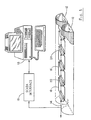
- FIG. 1 provides an illustration of a management arrangement for such a radio communication system.
- the system is shown serving a coverage area defined by a pair of tunnels 10 and 12 and includes a transceiver (not shown) coupled to a networked set of conductors 16, including radiating coaxial cables or "leaky” cables, at a port 14 near one end of the tunnels 10 and 12.
- the leaky cables 16 are used as an antenna to transmit information to and receive information from radio units operating within the tunnel coverage area.
- a preferred type of leaky cable is the RADIAX ⁇ cable, available from Andrew, Corp., Orland Park, Illinois.
- the management arrangement may be controlled from a control station 18, for example, a conventional personal computer, which is programmed to provide instructions to selected amplification devices 20 and to display their status.
- the amplification devices 20 are interconnected by the leaky cables 16 and are preferably intelligent, insofar as they are capable of communicating with the control station 18. Such communication may be accomplished using a conventional low frequency shift-keying scheme.
- the system shown in FIG. 1 involves two types of communication: radio communication between the radio units and the transceiver at port 14, and system management communication between the control station 18 and the amplification devices 14. Both types of communication may be implemented using the leaky cables 16 by modulating a carrier frequency with the information transmitted to and from the control station 18.
- the radio communication with the radio units may be implemented as described above, and the system management communication may be implemented by using separate conductors, for example, coaxial cable or a twisted pair of dedicated conductors.
- the separate conductors being part of the networked set of the conductors 16, should be capable of carrying signals over significant lengths, for example, up to 2 Km in length. Additionally, the signals carried over such distances should be received independently of DC bias levels and should be capable of handling long binary strings of ones and zeros.
- a PSK (phase-shift-keying) modulation format and/or conventional drivers, receivers and signal reconstruction circuits may be necessary to accommodate a given application.
- a preferred information packet includes: a header represented by a preselected synchronization code, an address to designate the amplification device to or from which the communication with the control station 18 is involved, the substantive information intended to be communicated, and, finally, a trailer which may include an error correcting code for data correction by the receiving device.
- SCADA Supervisory Control and Data Acquisition
- the substantive information carried in the packets preferably includes control and status information for remotely maintaining the operation of the system, and particularly for maintaining the operation of the conductors 16 and the amplification devices 20.
- control and status information may include requests for status reports from the control station 18 to one or more selected amplification devices to determine if carrier information is being received by the amplification device, if an excessive amount of power or current is being drawn or if any power is being provided to the amplification device.
- the status of the amplification devices may be selectively or continuously displayed on the CRT of the control station 18 or printed at a conventional printing station (not shown). Additionally, commands may be issued from the control station 18 to certain amplification devices to change parameters of the amplification devices or to reconfigure their operation.
- the communication protocol between the amplification devices and the control station 18 is preferably a polling technique controlled by the control station 18.
- the control station 18 polls each of the amplification devices at periodic intervals to determine the status of each amplification device.
- the amplification devices only transmit information in response to a request from the control station 18.
- a conventional carrier-sense-multiple-access (CSMA) protocol is preferably used as a back-up protocol.
- the CSMA protocol allows each amplification device to transmit status information to the control station 18 at regular intervals so long as it does not sense carrier present on the conductors carrying the system management communication. If carrier is present, indicating that another device is transmitting, the amplification device attempting to transmit delays for a random period before repeating the transmission attempt; thereby avoiding an otherwise inevitable communication collision.
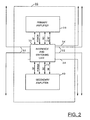
- FIG. 2 illustrates both radiating coaxial cables 32 and optional separate conductors 34; the latter being used for dedicated system management communication.
- Information carried by RF (radio frequency) energy is received over the radiating coaxial cables 32 and amplified by a primary amplifier 38 or a secondary (back-up) amplifier 40 before being passed on to the next tandem segment of radiating coaxial cables 32.
- the secondary amplifier 40 may be activated to replace the primary amplifier 38 in the event of a fault to the primary amplifier 38, or to alleviate the effect of another type of system fault.
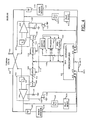
- the amplification device 20 is shown with particular detail directed to the operation of the ISU 30.
- radio communication is received on the radiating cables 32, routed through a cable switching unit 42, and coupled to a microcomputer 44 via bandpass filters 46 and 48 and pilot detectors 50 and 52.
- the cable switching unit 42 is controlled by the microcomputer 44, using control lines 54, to couple the radio frequency energy to the amplifiers 38 and 40 for system reconfiguration in the event of a fault, for example, a broken radiating coaxial cable 32.
- This type of cable fault may be detected on any one of the four cables 32 by the microcomputer 44 using the bandpass filters 46 and 48 and pilot detectors 50 and 52 to check the integrity of the cables 32.
- a 5 mega-Hertz pilot tone may be used throughout the system to indicate continuity in the path carrying the incoming or out-going carrier frequency (as transmitted from or to the radio units operating on the system).
- the bandpass filters 46 and 48 and the pilot detectors 50 and 52 are used to signal to the microcomputer 44 whether or not such continuity is intact.
- the absence of the pilot tone indicates a discontinuity or failure in the signal path and requires the microcomputer 44 to respond with a reconfiguration of the faulty RF communication path using the cable switching unit 42.
- the decisions behind this reconfiguration control can be performed at the control station 18.
- decision making can be automatically executed by the microcomputer 44 along with conventional address decoding circuitry 58 and program memory 60.
- the microcomputer 44 sends configuration data on lines 64 to a latch 66, which stores the configuration data for use by the cable switching unit 42.
- the configuration data is stored in non-volatile memory 68 and retrieved for re-programming the cable switching unit 42 when the malfunction is corrected.
- the microcomputer 44 may be implemented using an MC68HC11-type integrated circuit, available from Motorola, Inc., Schaumburg, Illinois.
- Serial communications links (SC) 70 and 72.
- a microcomputer 80 which also may be implemented using an MC68HC11-type integrated circuit, controls the operation of the amplifier based upon the information communicated over the serial communications link.
- each amplifier 38 or 40 The primary function of each amplifier 38 or 40 is to amplify the incoming and out-going signals received over the radiating coaxial cables 32, via the cable switching unit (CSU) 42.
- Each amplifier 38 or 40 is bidirectional in that each includes a pair of amplifier circuits 82 and 84 having their respective outputs connected to the other's respective inputs at RF ports 86 and 88.
- the amplifier circuits 82 and 84 differ only in that one amplifies the incoming signal, while the other amplifies the out-going signal.
- Bandpass filters 90 and 92 are situated at the input of the respective amplifier circuits 82 and 84 to differentiate the signals before they reach power amplification stages 94 and 96.
- the gain for the power amplification stages 94 and 96 is controlled by pair of gain input signals 98 and 100 which are generated by the microcomputer 80.
- the signals 98 and 100 are passed over the microcomputer data bus 100 and latched into latches 102 and 104 using a latch control signal 112, which is provided by an address bus decoder 114; the address bus decoder responds to the microcomputer's address and control lines, depicted as bus 115.
- Conventional digital-to-analog (D/A) converters 106 and 108 convert the digital signals at the latches 102 and 104 to set the gain at the amplification stages 94 and 96.
- D/A digital-to-analog
- the magnitude of the signals 98 and 100 may be determined directly at the amplifier 38 or 40 using program memory 110 or indirectly at the control station 38 using the system management communication. Preferably, these magnitudes are established at a normal level which is preprogrammed into a program memory 116 and altered only in response to a command received by the microcomputer 80 from the control station 18.
- the microcomputer 80 monitors the outputs of the amplifier circuits 82 and 84 to verify that the pilot signal generated throughout the system has passed through the amplification stages, and to determine the magnitudes of the current drawn and of the power generated by the amplification stages 94 and 96. Status information received by the microcomputer 80 that is associated with these parameters is passed along to the control station 18, for evaluation of faults. This evaluation may be accomplished by comparing the received status information with information that has been programmed into the control station memory.
- the microcomputer 80 checks the integrity of the amplifier 38 or 40 using bandpass filters 120 and 122, which pass only the system's pilot signal, and pilot tone detectors 124 and 126, which provide a binary indication of that integrity to the microcomputer 80.
- This pilot tone circuitry along with similar circuitry in the ISU, allows the user at the control station 18 to isolate loss of pilot tone to a problem at either a particular amplification device 20 or at a particular amplification stage 94 or 96.
- the microcomputer 80 determines the magnitudes of current drawn by the amplification stages 94 and 96 by monitoring a pair of voltage signals associated therewith at leads 130 and 132. These voltage signals are developed using resistors 134 and 136, which receive amplifier current signals that are proportional to the current actually drawn by the amplification stages 94 and 96. Analog buffers 138 and 140 are used to provide the corresponding analog signals for A/D converters, which are internal to the microcomputer 80.
- the microcomputer 80 determines the magnitudes of the power generated by the amplification stages 94 and 96 by monitoring a pair of power detect circuits, which are coupled to the outputs of the amplification stages 94 and 96 through signal rectification circuits 146 and 148.
- Monitoring the current drawn and the power generated by the amplification stages 94 and 96 allows the user at the control station 18 to monitor the status of each amplifier 38 and 40 for system maintenance and configuration control. For example, if the current monitoring process indicates that excessive current is being drawn by the amplification stages 94 and 96 at regular intervals, from the control station 18, the user may replace the amplifier 38 with the amplifier 40 using the system management communication. Similarly, adjustments to the power at the outputs of the amplification stages 94 and 96 can be controlled at the control station 18 by sending a command to adjust the gain of the amplification stages 94 and 96. All gain adjustment commands are preferably stored in non-volatile memory 150 for local reprogramming by the microcomputer 80 after a power failure.
- amplifier circuits 82 and 84 are depicted as a single stage, any number of amplification stages may be used to provide the necessary amplification for the system.
- the multiple amplification stages used in conventional cellular radio units may be used to implement the amplification circuits 82 and 84.
- gain control and power and current monitoring by the microcomputer 80 is preferably performed as described above.
- control functions provided using the control station can be locally provided using a keyboard and display directly coupled with the microcomputer 44 or 80.
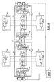
- FIG. 5 provides a detailed view of two CSUs 42 and 42', shown within respective ISUs 30 and 30' in the context of a system diagram.
- the system illustrated in FIG. 5 is the same as the system of FIG. 1 except for two differences.
- the first difference is the presence of transmitter (Tx) and receiver (Rx) base station equipment 160 and 162 at both ends of the radiating coaxial cable 32 in FIG. 5, wherein FIG. 1 represents such equipment only at one end (at port 14) of the radiating coaxial cable 32.
- the second difference is that, unlike the system illustrated in FIG. 1, the system in FIG. 5 includes an optional communication path along a third line of radiating coaxial cable 32 for application in a third respective tunnel.
- Each of the CSUs 42 and 42' includes conventional two-pole and three-pole reed switches 164-182 and 164'-182' and conventional power divider/summers 184-186 and 184'-186'.
- the reed switches are controlled using peripheral ports of the microcomputer 44 of the ISU 30.
- the reed switches are changed from their normal positions, as shown in FIG. 5, in response to commands from the control station 18, to overcome faults and to reconfigure the system as may be required.
- the divider/summers 184-186 and 184'-186' are used with the reed switches to provide additional configuration flexibility for the system.
- the system of FIG. 5 carries RF and system management information from the base station equipment 160 and from the control station 18 along the radiating coaxial cable 32 from left to right, and returns information (from radio units) to the base station equipment 160 and to the control station 18 along the radiating coaxial cable 32 from right to left.
- the base station equipment 160 is considered the primary equipment which is used in normal operation.
- the base station equipment 162 is considered standby equipment, which is used in the event of certain system faults.
- the RF and system management information traveling from the left (“forward signals") is carried on all radiating coaxial cables 32, but carried through the CSUs 42 and 42' only from the radiating coaxial cables 32 connected to the reed switches 168 and 168', respectively.
- this normal configuration passes forward signals through the reed switches 168-172, the amplification circuit 82, the reed switches 174-176, the divider/summer 186, the reed switches 178-182, the radiating coaxial cables 32 between the CSUs 42 and 42', the reed switches 168'-172', the amplification circuit 82', the reed switches 174'-176', the divider/summer 186', the reed switches 178'-182' and the radiating coaxial cables 32 connected to the reed switches 178'-182'.
- the RF and system management information traveling from the right (“reverse signals") is carried from any and all radiating coaxial cables 32 and combined at the divider/combiner 186 or 186' in each CSU 42 or 42', respectively.
- this configuration passes reverse signals through the reed switches 178'-182', the divider/combiner 186', the reed switches 176'-174', the amplification circuit 84', the reed switches 172'-170', and the reed switch 168' and its associated radiating coaxial cable 32. Additional signals picked-up by the radiating coaxial cables 32 between the CSUs 42 and 42' are passed along to the CSU 42 with the reverse signals routed through the reed switch 168'.
- Both sets of reverse signals are passed through the reed switches 178-182, the divider/combiner 186, the reed switches 176-174, the amplification circuit 84, the reed switches 172-170 and the reed switch 168 and its associated radiating coaxial cable 32 before reaching the base station equipment 160.
- the system illustrated in FIG. 5 may be easily reconfigured in the event of a fault by using the reed switches in the CSUs to change the communication paths which carry the information to and/or from the base station equipment 160 and the control station 18.
- the structure of the CSUs 42 provides for an endless number of reconfigurations. For example, if the microcomputer 80 detects that an excessive amount of current is being drawn from the amplification circuit 82 in the amplifier 38, the microcomputer reports the problem to the control station 18. The control station 18 then issues a command to the microcomputer 44 in the ISU 30, using system management communication, instructing that the microcomputer 44 replace the primary amplifier 38 with the secondary amplifier 40. This is accomplished, using the peripheral outputs of the microcomputer 44, by reversing the connections of the poles on the reed switches 172 and 174 to allow both forward and reverse information to be amplified by the secondary amplifier 40.
- FIG. 6 which illustrates the same system as shown in FIG. 5, is provided to demonstrate how a break in one of the radiating coaxial cables 32 may be overcome through a system reconfiguration. More specifically, FIG. 6 illustrates one way in which the system may be reconfigured if a cable brake is detected at point 190 by the microcomputer 44' of the ISU 30'; for example, in the event the pilot detect circuit 50' indicates that the pilot tone in the forward direction is absent. In response to this condition, the system reconfigures itself by changing the pole connections of the reed switches 166', 168', 170', 176', 178', 180' and 182', as shown in FIG. 6, and by activating the standby base station equipment 162.
- a second fault in the cables 32 may be accommodated.
- the system can be reconfigured as shown in FIG. 6 with only one difference. The difference relates to reed switch 168' and requires its pole to be in the down position so that it connects to the divider/summer 184'.
- forward signals pass from the switch 182', through the reed switches 170'-172', through the amplifier circuit 82', through the reed switches 174'-176', through the divider/summer 184' and out through the reed switches 166' and 168'.
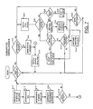
- FIG. 7 illustrates a flow chart which may be used to program the control station 18 of Figure 1 to establish the previously discussed system management communication between the control station and the amplification devices 20.
- the flow chart begins at block 200 where a test is performed by the control station to determine if the user of the control station has made a request to interface with one of the amplification devices; hereinafter, this request is referred to as a "user interface request.” If such a request has not been made, flow proceeds from block 200 to block 210 where the control station interrogates the status of each of the system's in-service amplifiers. This is accomplished by the control station sending a status request command to each ISU, instructing each ISU to report the status of the in-service amplifiers connected thereto.
- An ISU interrogation preferably includes each ISU verifying that its serial communication ports are operating properly, and that the pilot tone is being detected.
- control station compares the information reported by the ISU's to preprogrammed parameters stored in the control station memory. Using this comparison to determine the acceptability of the information , at block 218, the control station determines whether or not a fault is present in one of the ISU's. If no fault is detected at any of the ISU's, flow returns to block 210. If a fault is detected, flow proceeds to block 220 where the control station reports the fault as an alarm.
- FIG. 8 illustrates a flow chart which may be used to program the microcomputer 44 of the ISU.
- the flow chart begins at block 252 where the microcomputer waits until it is completely powered up. From block 252, flow proceeds to block 254 where a test is performed to determine if the non-volatile memory has been programmed with customized positions for the reed switches in the CSU. This may be accomplished by programming a portion of the non-volatile memory with a special code when it is programmed with customized positions. Presence of the special code indicates that customized positions have been programmed.
- a test is performed to determine if the control station has attempted communication with the CSU. If no communication from the control station has been requested, flow proceeds from block 260 to block 262 where the ISU begins its normal mode of monitoring the ISU and its associated amplifiers.
- the ISU determines if pilot tone is reaching the ISU properly. From block 262 flow proceeds to block 254 where the ISU communicates with the microcomputers in the associated amplifiers to determine if pilot tone is passing through the amplifiers. At block 266 and block 267, the ISU communicates with the amplifiers to determine the status of both the power detectors and the current sense lines associated with each amplifier circuit. As discussed in connection with FIG. 3, all such communication between the microcomputer 44 of the ISU and the microcomputer 80 of the amplifiers 38 and 40 is performed using the serial communication buses (CS).
- CS serial communication buses
- the microcomputer and the associated amplifier can be instructed to test the lock time of the phase-locked-loop and to report that lock time to the ISU.
- the status checks discussed in connection with blocks 262 and 267 are evaluated by the microcomputer in the ISU to determine if a fault is present, depicted at block 270. If a fault is detected, that fault is reported to the control station for display to the user and flow returns to block 260. If no faults are detected between blocks 262 and 267, flow returns from block 270 to block 260.
- the communication from the control station does not involve a status request, the communication is interpreted as a maintenance command which is decoded at block 278.
- the ISU determines if the maintenance command involves a system reconfiguration. If a system reconfiguration has been requested, flow proceeds to block 282 where the designated reed switches are set as requested to accomplish the reconfiguration. From block 282, flow returns to block 260.
- flow defaults to block 284 where a test is performed to determine if the maintenance command involves merely testing the serial communication ports between the ISU and the amplifiers. If so, flow proceeds to block 286 where the serial communication ports are tested and reported on for the control station. If the user interface request does not involve testing the serial communication ports, the communication from the control station is a gain adjustment request, and flow proceeds from block 284 to block 288 where the program sets the gain of the designated amplifier stage. From blocks 286 and 288, flow returns to block 260.
- FIG. 9 illustrates a flow chart which may be used to program the microcomputer 80 in the amplifier 38 or 40.
- the flow chart begins at block 294 where the microcomputer waits until it is completely powered up. From block 294, flow proceeds to block 296 where a test is performed to determine if there is valid data in the nonvolatile memory for storing a designated gain at the input of the amplifier circuits. If the nonvolatile memory contains valid data for this purpose, flow proceeds from block 296 to block 298 where the microcomputer sets the gain in the amplifier circuits. If the data in the nonvolatile memory has not been programmed with such data, flow proceeds to block 300 where the gain of the amplifier circuits is set to a default level which has been previously programmed into the program memory for the microcomputer 80. From blocks 298 and 300, flow proceeds to block 302.
- a test is performed to determine if there has been a communication request from the ISU to the microcomputer 80 in the amplifier. If not, flow returns to block 302, and the microcomputer 80 continues to wait for such a request.
- a test is performed to determine if the communication from the ISU is a request to adjust the gain of the amplifier circuits. If the communication concerns such a gain adjustment, flow proceeds from block 304 to block 306 where the new gain level is set at the designated amplifier circuits. Flow returns from block 306 to block 302.
- the communication request from the ISU involves a status request
- flow defaults from block 308 to block 312 where the microcomputer determines the status of the amplification device, as instructed in the communication from the ISU, and reports such status to the ISU. From block 312, flow returns to block 302.
Landscapes
- Engineering & Computer Science (AREA)
- Computer Networks & Wireless Communication (AREA)
- Signal Processing (AREA)
- Data Exchanges In Wide-Area Networks (AREA)
- Selective Calling Equipment (AREA)
- Mobile Radio Communication Systems (AREA)
- Near-Field Transmission Systems (AREA)
- Amplifiers (AREA)
- Monitoring And Testing Of Transmission In General (AREA)
Applications Claiming Priority (2)
| Application Number | Priority Date | Filing Date | Title |
|---|---|---|---|
| US46712190A | 1990-01-18 | 1990-01-18 | |
| US467121 | 1995-06-06 |
Publications (3)
| Publication Number | Publication Date |
|---|---|
| EP0439022A2 true EP0439022A2 (fr) | 1991-07-31 |
| EP0439022A3 EP0439022A3 (en) | 1994-06-01 |
| EP0439022B1 EP0439022B1 (fr) | 2000-06-07 |
Family
ID=23854449
Family Applications (1)
| Application Number | Title | Priority Date | Filing Date |
|---|---|---|---|
| EP91100244A Expired - Lifetime EP0439022B1 (fr) | 1990-01-18 | 1991-01-09 | Amplificateur distribué pour système de gestion de réseau |
Country Status (6)
| Country | Link |
|---|---|
| US (1) | US5278989A (fr) |
| EP (1) | EP0439022B1 (fr) |
| AT (1) | ATE193792T1 (fr) |
| AU (1) | AU632891B2 (fr) |
| CA (1) | CA2033763C (fr) |
| DE (1) | DE69132246T2 (fr) |
Families Citing this family (68)
| Publication number | Priority date | Publication date | Assignee | Title |
|---|---|---|---|---|
| IE70073B1 (en) * | 1990-12-14 | 1996-10-30 | Ainsworth Tech Inc | Communication system |
| US5377255A (en) * | 1992-07-14 | 1994-12-27 | Pcs Microcell International Inc. | RF repeaters for time division duplex cordless telephone systems |
| US5404570A (en) * | 1992-11-23 | 1995-04-04 | Telefonaktiebolaget L M Ericsson | Radio coverage in closed environments |
| US5669065A (en) * | 1994-09-15 | 1997-09-16 | Mine Radio Systems Inc. | Completely redundant communication system utilizing radiating transmission line |
| US6530088B1 (en) * | 1996-06-03 | 2003-03-04 | Scientific-Atlanta, Inc. | Apparatus for automatic sensing of line amplifier configuration for status monitoring |
| US6023612A (en) * | 1996-07-05 | 2000-02-08 | Thomcast Communications, Inc. | Modular transmission system and method |
| US6052558A (en) * | 1997-04-28 | 2000-04-18 | Motorola, Inc. | Networked repeater |
| US6032020A (en) * | 1997-07-28 | 2000-02-29 | Motorola, Inc. | Multi-repeater communication system |
| US6324276B1 (en) | 1999-02-12 | 2001-11-27 | Telera, Inc. | Point-of-presence call center management system |
| IL159838A0 (en) | 2004-01-13 | 2004-06-20 | Yehuda Binder | Information device |
| US7616968B2 (en) * | 2004-03-23 | 2009-11-10 | Mine Radio Systems Inc. | System and method to facilitate overcoming a degradation in transmission through a radiating transmission line communication system |
| US8873585B2 (en) * | 2006-12-19 | 2014-10-28 | Corning Optical Communications Wireless Ltd | Distributed antenna system for MIMO technologies |
| JP4436388B2 (ja) * | 2007-07-13 | 2010-03-24 | 東芝テック株式会社 | 無線通信システム |
| US20100054746A1 (en) | 2007-07-24 | 2010-03-04 | Eric Raymond Logan | Multi-port accumulator for radio-over-fiber (RoF) wireless picocellular systems |
| US8175459B2 (en) | 2007-10-12 | 2012-05-08 | Corning Cable Systems Llc | Hybrid wireless/wired RoF transponder and hybrid RoF communication system using same |
| US8644844B2 (en) | 2007-12-20 | 2014-02-04 | Corning Mobileaccess Ltd. | Extending outdoor location based services and applications into enclosed areas |
| US9673904B2 (en) | 2009-02-03 | 2017-06-06 | Corning Optical Communications LLC | Optical fiber-based distributed antenna systems, components, and related methods for calibration thereof |
| WO2010091004A1 (fr) | 2009-02-03 | 2010-08-12 | Corning Cable Systems Llc | Systèmes et composants d'antennes distribuées à base de fibres optiques, et procédés de calibrage associés |
| AU2010210766A1 (en) | 2009-02-03 | 2011-09-15 | Corning Cable Systems Llc | Optical fiber-based distributed antenna systems, components, and related methods for monitoring and configuring thereof |
| US9590733B2 (en) | 2009-07-24 | 2017-03-07 | Corning Optical Communications LLC | Location tracking using fiber optic array cables and related systems and methods |
| US8280259B2 (en) | 2009-11-13 | 2012-10-02 | Corning Cable Systems Llc | Radio-over-fiber (RoF) system for protocol-independent wired and/or wireless communication |
| US8275265B2 (en) | 2010-02-15 | 2012-09-25 | Corning Cable Systems Llc | Dynamic cell bonding (DCB) for radio-over-fiber (RoF)-based networks and communication systems and related methods |
| EP2553839A1 (fr) | 2010-03-31 | 2013-02-06 | Corning Cable Systems LLC | Services de localisation dans des composants et systèmes de communications distribués à base de fibres optiques et procédés connexes |
| US8570914B2 (en) | 2010-08-09 | 2013-10-29 | Corning Cable Systems Llc | Apparatuses, systems, and methods for determining location of a mobile device(s) in a distributed antenna system(s) |
| US9160449B2 (en) | 2010-10-13 | 2015-10-13 | Ccs Technology, Inc. | Local power management for remote antenna units in distributed antenna systems |
| US9252874B2 (en) | 2010-10-13 | 2016-02-02 | Ccs Technology, Inc | Power management for remote antenna units in distributed antenna systems |
| EP2643947B1 (fr) | 2010-11-24 | 2018-09-19 | Corning Optical Communications LLC | Module(s) de distribution d'énergie électrique capable(s) d'une connexion et/ou déconnexion à chaud pour des systèmes d'antennes réparties, et unités d'énergie électrique, composants et procédés associés |
| US11296504B2 (en) | 2010-11-24 | 2022-04-05 | Corning Optical Communications LLC | Power distribution module(s) capable of hot connection and/or disconnection for wireless communication systems, and related power units, components, and methods |
| US9099956B2 (en) | 2011-04-26 | 2015-08-04 | King Abdulaziz City For Science And Technology | Injection locking based power amplifier |
| WO2012148938A1 (fr) | 2011-04-29 | 2012-11-01 | Corning Cable Systems Llc | Détermination de temps de propagation de communications dans systèmes d'antennes distribuées, et composants, systèmes et procédés associés |
| EP2702780A4 (fr) | 2011-04-29 | 2014-11-12 | Corning Cable Sys Llc | Systèmes, procédés et dispositifs pour augmenter la puissance radiofréquence (rf) dans systèmes d'antennes distribuées |
| US8700026B2 (en) | 2011-05-10 | 2014-04-15 | King Abdulaziz City For Science And Technology | Controlled mobile communication as a service in a coverage area bounded by radiating cables |
| WO2013148986A1 (fr) | 2012-03-30 | 2013-10-03 | Corning Cable Systems Llc | Réduction d'un brouillage lié à la position dans des systèmes d'antennes distribuées fonctionnant selon une configuration à entrées multiples et à sorties multiples (mimo), et composants, systèmes et procédés associés |
| US9781553B2 (en) | 2012-04-24 | 2017-10-03 | Corning Optical Communications LLC | Location based services in a distributed communication system, and related components and methods |
| WO2013162988A1 (fr) | 2012-04-25 | 2013-10-31 | Corning Cable Systems Llc | Architectures de système d'antenne distribué |
| US9154222B2 (en) | 2012-07-31 | 2015-10-06 | Corning Optical Communications LLC | Cooling system control in distributed antenna systems |
| WO2014024192A1 (fr) | 2012-08-07 | 2014-02-13 | Corning Mobile Access Ltd. | Distribution de services de gestion multiplexés par répartition dans le temps (tdm) dans un système d'antennes distribuées, et composants, systèmes et procédés associés |
| US9455784B2 (en) | 2012-10-31 | 2016-09-27 | Corning Optical Communications Wireless Ltd | Deployable wireless infrastructures and methods of deploying wireless infrastructures |
| US10257056B2 (en) | 2012-11-28 | 2019-04-09 | Corning Optical Communications LLC | Power management for distributed communication systems, and related components, systems, and methods |
| CN105308876B (zh) | 2012-11-29 | 2018-06-22 | 康宁光电通信有限责任公司 | 分布式天线系统中的远程单元天线结合 |
| US9647758B2 (en) | 2012-11-30 | 2017-05-09 | Corning Optical Communications Wireless Ltd | Cabling connectivity monitoring and verification |
| US9158864B2 (en) | 2012-12-21 | 2015-10-13 | Corning Optical Communications Wireless Ltd | Systems, methods, and devices for documenting a location of installed equipment |
| US9497706B2 (en) | 2013-02-20 | 2016-11-15 | Corning Optical Communications Wireless Ltd | Power management in distributed antenna systems (DASs), and related components, systems, and methods |
| EP3008515A1 (fr) | 2013-06-12 | 2016-04-20 | Corning Optical Communications Wireless, Ltd | Coupleur directif optique a commande en tension |
| EP3008828B1 (fr) | 2013-06-12 | 2017-08-09 | Corning Optical Communications Wireless Ltd. | Duplexage par répartition temporelle (tdd) dans des systèmes de communication répartis, comprenant des systèmes d'antenne répartis (das) |
| US9247543B2 (en) | 2013-07-23 | 2016-01-26 | Corning Optical Communications Wireless Ltd | Monitoring non-supported wireless spectrum within coverage areas of distributed antenna systems (DASs) |
| US9661781B2 (en) | 2013-07-31 | 2017-05-23 | Corning Optical Communications Wireless Ltd | Remote units for distributed communication systems and related installation methods and apparatuses |
| EP3039814B1 (fr) | 2013-08-28 | 2018-02-21 | Corning Optical Communications Wireless Ltd. | Gestion de énergie pour des systèmes de communication distribués, et composants, systèmes et procédés associés |
| US9385810B2 (en) | 2013-09-30 | 2016-07-05 | Corning Optical Communications Wireless Ltd | Connection mapping in distributed communication systems |
| WO2015079435A1 (fr) | 2013-11-26 | 2015-06-04 | Corning Optical Communications Wireless Ltd. | Activation sélective des services de communication lors de la mise sous tension d'une ou plusieurs unités distantes dans un système d'antennes distribuées (das) basé sur la consommation d'énergie |
| US9178635B2 (en) | 2014-01-03 | 2015-11-03 | Corning Optical Communications Wireless Ltd | Separation of communication signal sub-bands in distributed antenna systems (DASs) to reduce interference |
| US9775123B2 (en) | 2014-03-28 | 2017-09-26 | Corning Optical Communications Wireless Ltd. | Individualized gain control of uplink paths in remote units in a distributed antenna system (DAS) based on individual remote unit contribution to combined uplink power |
| US9357551B2 (en) | 2014-05-30 | 2016-05-31 | Corning Optical Communications Wireless Ltd | Systems and methods for simultaneous sampling of serial digital data streams from multiple analog-to-digital converters (ADCS), including in distributed antenna systems |
| US9509133B2 (en) | 2014-06-27 | 2016-11-29 | Corning Optical Communications Wireless Ltd | Protection of distributed antenna systems |
| US9525472B2 (en) | 2014-07-30 | 2016-12-20 | Corning Incorporated | Reducing location-dependent destructive interference in distributed antenna systems (DASS) operating in multiple-input, multiple-output (MIMO) configuration, and related components, systems, and methods |
| US9730228B2 (en) | 2014-08-29 | 2017-08-08 | Corning Optical Communications Wireless Ltd | Individualized gain control of remote uplink band paths in a remote unit in a distributed antenna system (DAS), based on combined uplink power level in the remote unit |
| US9653861B2 (en) | 2014-09-17 | 2017-05-16 | Corning Optical Communications Wireless Ltd | Interconnection of hardware components |
| US9602210B2 (en) | 2014-09-24 | 2017-03-21 | Corning Optical Communications Wireless Ltd | Flexible head-end chassis supporting automatic identification and interconnection of radio interface modules and optical interface modules in an optical fiber-based distributed antenna system (DAS) |
| US9420542B2 (en) | 2014-09-25 | 2016-08-16 | Corning Optical Communications Wireless Ltd | System-wide uplink band gain control in a distributed antenna system (DAS), based on per band gain control of remote uplink paths in remote units |
| US9729267B2 (en) | 2014-12-11 | 2017-08-08 | Corning Optical Communications Wireless Ltd | Multiplexing two separate optical links with the same wavelength using asymmetric combining and splitting |
| US20160249365A1 (en) | 2015-02-19 | 2016-08-25 | Corning Optical Communications Wireless Ltd. | Offsetting unwanted downlink interference signals in an uplink path in a distributed antenna system (das) |
| US9785175B2 (en) | 2015-03-27 | 2017-10-10 | Corning Optical Communications Wireless, Ltd. | Combining power from electrically isolated power paths for powering remote units in a distributed antenna system(s) (DASs) |
| US9681313B2 (en) | 2015-04-15 | 2017-06-13 | Corning Optical Communications Wireless Ltd | Optimizing remote antenna unit performance using an alternative data channel |
| US9948349B2 (en) | 2015-07-17 | 2018-04-17 | Corning Optical Communications Wireless Ltd | IOT automation and data collection system |
| US10560214B2 (en) | 2015-09-28 | 2020-02-11 | Corning Optical Communications LLC | Downlink and uplink communication path switching in a time-division duplex (TDD) distributed antenna system (DAS) |
| US9648580B1 (en) | 2016-03-23 | 2017-05-09 | Corning Optical Communications Wireless Ltd | Identifying remote units in a wireless distribution system (WDS) based on assigned unique temporal delay patterns |
| US10236924B2 (en) | 2016-03-31 | 2019-03-19 | Corning Optical Communications Wireless Ltd | Reducing out-of-channel noise in a wireless distribution system (WDS) |
| CN111194036A (zh) * | 2018-11-14 | 2020-05-22 | 中移(杭州)信息技术有限公司 | 一种家庭无线组网的方法及装置 |
Family Cites Families (22)
| Publication number | Priority date | Publication date | Assignee | Title |
|---|---|---|---|---|
| US2980793A (en) * | 1956-06-11 | 1961-04-18 | Electronic Safety Engineering | Restricted range radio transmitting system |
| NL290708A (fr) * | 1962-03-27 | |||
| US3519935A (en) * | 1966-06-21 | 1970-07-07 | Bell Telephone Labor Inc | Arrangement for providing partial service on a failed serially looped carrier system |
| GB1235888A (en) * | 1967-08-17 | 1971-06-16 | Sumitomo Electric Industries | Improvements in or relating to radio transmission systems for communication with moving bodies |
| GB1371291A (en) * | 1972-05-09 | 1974-10-23 | Coal Industry Patents Ltd | Radio frequency communication systems |
| BE799885R (fr) * | 1972-05-26 | 1973-09-17 | Thomson Csf | Perfectionnements aux dispositifs d'intercommunication a rayonnement limite, |
| GB1389554A (en) * | 1972-05-26 | 1975-04-03 | Coal Industry Patents Ltd | Radiating line transmission system |
| GB1491468A (en) * | 1974-08-07 | 1977-11-09 | Coal Ind | Radiating line telecommunication systems |
| GB1485156A (en) * | 1974-08-07 | 1977-09-08 | Coal Ind | Radiating line telecommunication systems |
| GB1497288A (en) * | 1975-03-07 | 1978-01-05 | Coal Ind | Telecommunication system |
| JPS5484403A (en) * | 1977-12-19 | 1979-07-05 | Hitachi Ltd | Double system transmission line switching system |
| JPS54102815A (en) * | 1978-01-17 | 1979-08-13 | Toshiba Corp | Coaxial leakage communication system |
| JPS55100758A (en) * | 1979-01-26 | 1980-07-31 | Nec Corp | Fault-point orientation system |
| JPS5660121A (en) * | 1979-10-19 | 1981-05-23 | Nec Corp | Circuit switching system |
| JPS59172841A (ja) * | 1983-03-22 | 1984-09-29 | Hitachi Denshi Ltd | トンネル内通信方式 |
| GB8413598D0 (en) * | 1984-05-29 | 1984-07-04 | Thorn Emi Ferguson | Mainsborne network |
| JPS6223244A (ja) * | 1985-07-22 | 1987-01-31 | Nec Corp | 中継伝送方式 |
| JPS62110206A (ja) * | 1985-11-08 | 1987-05-21 | 住友電気工業株式会社 | 漏洩ケ−ブル及びそれを用いた無線システム |
| JPS62136928A (ja) * | 1985-12-11 | 1987-06-19 | Matsushita Electric Ind Co Ltd | 電力線搬送用増幅装置 |
| US4847837A (en) * | 1986-11-07 | 1989-07-11 | The United States Of America As Represented By The Administrator Of The National Aeronautics And Space Administration | Local area network with fault-checking, priorities and redundant backup |
| DE3710455A1 (de) * | 1987-03-30 | 1988-10-20 | Licentia Gmbh | Verfahren zur uebertragung von funksignalen und funkuebertragungssystem zur ausfuehrung des verfahrens |
| US4784240A (en) * | 1988-03-16 | 1988-11-15 | Westinghouse Electric Corp. | Method for using door cycle time in dispatching elevator cars |
-
1991
- 1991-01-08 CA CA002033763A patent/CA2033763C/fr not_active Expired - Fee Related
- 1991-01-08 AU AU69225/91A patent/AU632891B2/en not_active Ceased
- 1991-01-09 EP EP91100244A patent/EP0439022B1/fr not_active Expired - Lifetime
- 1991-01-09 DE DE69132246T patent/DE69132246T2/de not_active Expired - Fee Related
- 1991-01-09 AT AT91100244T patent/ATE193792T1/de not_active IP Right Cessation
-
1992
- 1992-06-24 US US07/905,081 patent/US5278989A/en not_active Expired - Fee Related
Also Published As
| Publication number | Publication date |
|---|---|
| EP0439022A3 (en) | 1994-06-01 |
| US5278989A (en) | 1994-01-11 |
| DE69132246D1 (de) | 2000-07-13 |
| AU6922591A (en) | 1991-07-25 |
| CA2033763A1 (fr) | 1991-07-19 |
| DE69132246T2 (de) | 2000-10-26 |
| EP0439022B1 (fr) | 2000-06-07 |
| CA2033763C (fr) | 1994-11-01 |
| ATE193792T1 (de) | 2000-06-15 |
| AU632891B2 (en) | 1993-01-14 |
Similar Documents
| Publication | Publication Date | Title |
|---|---|---|
| US5278989A (en) | Distributed amplifier network management system | |
| EP0442259B1 (fr) | Système régénératif d'amplificateur bidirectionnel à fréquence radio | |
| US6047199A (en) | Systems and methods for transmitting mobile radio signals | |
| US5239666A (en) | Mobile detector using RSSI for vehicular repeater prioritization | |
| US5551056A (en) | Method for securing the operation of a telecommunications network in a cellular radio system and a base station arrangement | |
| CN1132007A (zh) | 基站的安全操作的方法 | |
| US11563549B2 (en) | Selectable band suppression for a distributed antenna system | |
| KR102671341B1 (ko) | 중계기 직렬 연결방식에 의한 다채널 무선통신 신호 중계 시스템 | |
| US6438359B1 (en) | Dual transmitter arrangement with back-up switching | |
| US6690916B1 (en) | Radio network for radio communication in an enclosed environment and a repeater for such a radio network | |
| US4242756A (en) | Multiline switching protection apparatus | |
| JP2003244047A (ja) | 衛星通信方式 | |
| US6097929A (en) | Method and system for monitoring and controlling a single channel per carrier satellite link between two remote earth stations | |
| US5669065A (en) | Completely redundant communication system utilizing radiating transmission line | |
| KR102029161B1 (ko) | 터널 내의 통신 서비스 운용 방법 | |
| KR100501221B1 (ko) | 디지털 위성방송 중계장치 | |
| KR100204167B1 (ko) | 무선호출 데이터 전송 시스템의 상향링크 전력제어기의 이중화 제어장치 | |
| CA2164683C (fr) | Systeme de communication a redondance integrale utilisant une ligne de transmission rayonnante | |
| GB2300333A (en) | Confined space telecommunications system; transmitter power control | |
| JPH0644743B2 (ja) | マルチチヤネルアクセスシステムの監視制御方式 | |
| JP2007158392A (ja) | 放送電波再送信システム及び分岐装置 | |
| KR0168915B1 (ko) | 아이에프엘 케이블의 길이에 따른 수식 신호 레벨 감쇄의 보상장치 | |
| Li et al. | Los Angeles Fot Spread Spectrum Radio Traffic Signal Interconnect Evaluation Task: Final Report On Full Deployment | |
| JPS6213135A (ja) | 電力線搬送通信システム | |
| JPH04291836A (ja) | If中継ディジタル無線装置および無線回線監視方法 |
Legal Events
| Date | Code | Title | Description |
|---|---|---|---|
| PUAI | Public reference made under article 153(3) epc to a published international application that has entered the european phase |
Free format text: ORIGINAL CODE: 0009012 |
|
| AK | Designated contracting states |
Kind code of ref document: A2 Designated state(s): AT CH DE FR GB IT LI |
|
| PUAL | Search report despatched |
Free format text: ORIGINAL CODE: 0009013 |
|
| AK | Designated contracting states |
Kind code of ref document: A3 Designated state(s): AT CH DE FR GB IT LI |
|
| 17P | Request for examination filed |
Effective date: 19940714 |
|
| GRAG | Despatch of communication of intention to grant |
Free format text: ORIGINAL CODE: EPIDOS AGRA |
|
| 17Q | First examination report despatched |
Effective date: 19961223 |
|
| GRAG | Despatch of communication of intention to grant |
Free format text: ORIGINAL CODE: EPIDOS AGRA |
|
| GRAG | Despatch of communication of intention to grant |
Free format text: ORIGINAL CODE: EPIDOS AGRA |
|
| GRAH | Despatch of communication of intention to grant a patent |
Free format text: ORIGINAL CODE: EPIDOS IGRA |
|
| GRAH | Despatch of communication of intention to grant a patent |
Free format text: ORIGINAL CODE: EPIDOS IGRA |
|
| GRAA | (expected) grant |
Free format text: ORIGINAL CODE: 0009210 |
|
| AK | Designated contracting states |
Kind code of ref document: B1 Designated state(s): AT CH DE FR GB IT LI |
|
| REF | Corresponds to: |
Ref document number: 193792 Country of ref document: AT Date of ref document: 20000615 Kind code of ref document: T |
|
| REG | Reference to a national code |
Ref country code: CH Ref legal event code: NV Representative=s name: PATENTANWALTSBUERO JEAN HUNZIKER Ref country code: CH Ref legal event code: EP |
|
| ITF | It: translation for a ep patent filed | ||
| REF | Corresponds to: |
Ref document number: 69132246 Country of ref document: DE Date of ref document: 20000713 |
|
| ET | Fr: translation filed | ||
| PGFP | Annual fee paid to national office [announced via postgrant information from national office to epo] |
Ref country code: DE Payment date: 20010102 Year of fee payment: 11 |
|
| PGFP | Annual fee paid to national office [announced via postgrant information from national office to epo] |
Ref country code: GB Payment date: 20010103 Year of fee payment: 11 |
|
| PGFP | Annual fee paid to national office [announced via postgrant information from national office to epo] |
Ref country code: CH Payment date: 20010112 Year of fee payment: 11 |
|
| PGFP | Annual fee paid to national office [announced via postgrant information from national office to epo] |
Ref country code: AT Payment date: 20010116 Year of fee payment: 11 |
|
| PGFP | Annual fee paid to national office [announced via postgrant information from national office to epo] |
Ref country code: FR Payment date: 20010125 Year of fee payment: 11 |
|
| PLBE | No opposition filed within time limit |
Free format text: ORIGINAL CODE: 0009261 |
|
| STAA | Information on the status of an ep patent application or granted ep patent |
Free format text: STATUS: NO OPPOSITION FILED WITHIN TIME LIMIT |
|
| 26N | No opposition filed | ||
| REG | Reference to a national code |
Ref country code: GB Ref legal event code: IF02 |
|
| PG25 | Lapsed in a contracting state [announced via postgrant information from national office to epo] |
Ref country code: GB Free format text: LAPSE BECAUSE OF NON-PAYMENT OF DUE FEES Effective date: 20020109 Ref country code: AT Free format text: LAPSE BECAUSE OF NON-PAYMENT OF DUE FEES Effective date: 20020109 |
|
| PG25 | Lapsed in a contracting state [announced via postgrant information from national office to epo] |
Ref country code: LI Free format text: LAPSE BECAUSE OF NON-PAYMENT OF DUE FEES Effective date: 20020131 Ref country code: CH Free format text: LAPSE BECAUSE OF NON-PAYMENT OF DUE FEES Effective date: 20020131 |
|
| PG25 | Lapsed in a contracting state [announced via postgrant information from national office to epo] |
Ref country code: DE Free format text: LAPSE BECAUSE OF NON-PAYMENT OF DUE FEES Effective date: 20020801 |
|
| GBPC | Gb: european patent ceased through non-payment of renewal fee |
Effective date: 20020109 |
|
| REG | Reference to a national code |
Ref country code: CH Ref legal event code: PL |
|
| PG25 | Lapsed in a contracting state [announced via postgrant information from national office to epo] |
Ref country code: FR Free format text: LAPSE BECAUSE OF NON-PAYMENT OF DUE FEES Effective date: 20020930 |
|
| REG | Reference to a national code |
Ref country code: FR Ref legal event code: ST |
|
| PG25 | Lapsed in a contracting state [announced via postgrant information from national office to epo] |
Ref country code: IT Free format text: LAPSE BECAUSE OF NON-PAYMENT OF DUE FEES;WARNING: LAPSES OF ITALIAN PATENTS WITH EFFECTIVE DATE BEFORE 2007 MAY HAVE OCCURRED AT ANY TIME BEFORE 2007. THE CORRECT EFFECTIVE DATE MAY BE DIFFERENT FROM THE ONE RECORDED. Effective date: 20050109 |