EP0439033A2 - Procédé pour fabriquer un volant de direction - Google Patents
Procédé pour fabriquer un volant de direction Download PDFInfo
- Publication number
- EP0439033A2 EP0439033A2 EP91100325A EP91100325A EP0439033A2 EP 0439033 A2 EP0439033 A2 EP 0439033A2 EP 91100325 A EP91100325 A EP 91100325A EP 91100325 A EP91100325 A EP 91100325A EP 0439033 A2 EP0439033 A2 EP 0439033A2
- Authority
- EP
- European Patent Office
- Prior art keywords
- core
- steering wheel
- molding
- dies
- gate
- Prior art date
- Legal status (The legal status is an assumption and is not a legal conclusion. Google has not performed a legal analysis and makes no representation as to the accuracy of the status listed.)
- Granted
Links
Images

Classifications
-
- B—PERFORMING OPERATIONS; TRANSPORTING
- B29—WORKING OF PLASTICS; WORKING OF SUBSTANCES IN A PLASTIC STATE IN GENERAL
- B29C—SHAPING OR JOINING OF PLASTICS; SHAPING OF MATERIAL IN A PLASTIC STATE, NOT OTHERWISE PROVIDED FOR; AFTER-TREATMENT OF THE SHAPED PRODUCTS, e.g. REPAIRING
- B29C45/00—Injection moulding, i.e. forcing the required volume of moulding material through a nozzle into a closed mould; Apparatus therefor
- B29C45/14—Injection moulding, i.e. forcing the required volume of moulding material through a nozzle into a closed mould; Apparatus therefor incorporating preformed parts or layers, e.g. injection moulding around inserts or for coating articles
-
- B—PERFORMING OPERATIONS; TRANSPORTING
- B62—LAND VEHICLES FOR TRAVELLING OTHERWISE THAN ON RAILS
- B62D—MOTOR VEHICLES; TRAILERS
- B62D1/00—Steering controls, i.e. means for initiating a change of direction of the vehicle
- B62D1/02—Steering controls, i.e. means for initiating a change of direction of the vehicle vehicle-mounted
- B62D1/04—Hand wheels
-
- B—PERFORMING OPERATIONS; TRANSPORTING
- B29—WORKING OF PLASTICS; WORKING OF SUBSTANCES IN A PLASTIC STATE IN GENERAL
- B29C—SHAPING OR JOINING OF PLASTICS; SHAPING OF MATERIAL IN A PLASTIC STATE, NOT OTHERWISE PROVIDED FOR; AFTER-TREATMENT OF THE SHAPED PRODUCTS, e.g. REPAIRING
- B29C45/00—Injection moulding, i.e. forcing the required volume of moulding material through a nozzle into a closed mould; Apparatus therefor
- B29C45/14—Injection moulding, i.e. forcing the required volume of moulding material through a nozzle into a closed mould; Apparatus therefor incorporating preformed parts or layers, e.g. injection moulding around inserts or for coating articles
- B29C45/14631—Coating reinforcements
-
- B—PERFORMING OPERATIONS; TRANSPORTING
- B29—WORKING OF PLASTICS; WORKING OF SUBSTANCES IN A PLASTIC STATE IN GENERAL
- B29L—INDEXING SCHEME ASSOCIATED WITH SUBCLASS B29C, RELATING TO PARTICULAR ARTICLES
- B29L2031/00—Other particular articles
- B29L2031/30—Vehicles, e.g. ships or aircraft, or body parts thereof
- B29L2031/3047—Steering wheels
Definitions
- the present invention relates to a method of manufacturing a steering wheel, and more particularly relates to a method of manufacturing a steering wheel, in which a coating layer is molded of a synthetic resin on a steering wheel core including an annular portion having a groove extending in the circumferential direction of the portion.
- the cross section of at least the annular portion of the core of a steering wheel is shaped as U in order to reduce the weight of the core, namely, the weight of the wheel as a whole, as disclosed in the Japan Utility Model Application (OPI) No. 16559/87 (the term “OPI” as used herein means an "unexamined published application”).
- OPI Japan Utility Model Application
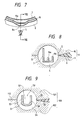
- the core thereof is set in a molding cavity 54 defined by an upper and a lower molding dies 101 and 102, so that the outermost part 53 of the groove 52 of the annular portion 51 of the core is located as the top of the groove, as shown in Fig. 9.
- a synthetic resin 56 such as urethane, polypropylene and vinyl chloride is then injected into the cavity 54 through a gate 55 provided at the separation surfaces 112 of a molding die unit 100 consisting of the molding dies 101 and 102, so that a coating layer is molded of the resin on the core.
- the synthetic resin injected through the gate 55 runs onto a wall 58 facing the gate and included in the annular portion 51 including another wall 57 and having the groove 52 defined between the walls 57 and 58 and gravitates on the wall 58 so that the resin starts filling the cavity 54 from the bottom thereof, the surface of the resin rises over the wall, and the resin flows down into the groove.
- the coating layer is likely to have a cavity therein.
- the speed of the filling of the cavity 54 with the resin from the bottom of the cavity changes at the time of the inflow of the resin into the groove 52 so that the outside surface of the coating layer is likely to have a luster nonuniformity. Since the coating layer is likely to have such molding defects, it is difficult to properly manufacture the steering wheel in a short time. This is a problem.
- the present invention was made in order to solve the problem mentioned above. Accordingly, it is an object of the present invention to provide a method of manufacturing a steering wheel in a short time so that a molding defect such as a cavity is less likely to be caused.
- a coating layer is molded of a synthetic resin, by using a molding die unit, on at least the annular portion of a steering wheel core including a boss, the annular portion located around the boss and having a groove extending in the circumferential direction of the annular portion, and spokes coupling the boss and the portion to each other.
- the method of the present invention is characterized by comprising a die opening step in which an upper and a lower molding dies, which have a gate formed at the separation surfaces of the dies and communicating with the molding cavity of the molding die unit, are opened from each other; a core setting step in which the steering wheel core is set in the molding cavity so that the outermost part of the groove of the annular portion having walls defining the groove between them is located as the top of the groove, one of the walls, which faces the gate and has a notched part notched to be smaller in height than the other of the walls, faces the gate at the notched part, and the top of the notched part is located below the separation surfaces of the dies; a coating layer molding step in which the dies are closed on each other and the synthetic resin is injected into the molding cavity through the gate so that the coating layer is molded of the resin on the core; and a steering wheel takeout step in which the die are opened from each other and the wheel is taken out from the dies.
- the synthetic resin first flows into the groove of the annular portion of the core through the notched part of the portion, and thereafter starts filling the molding cavity from the bottom thereof gradually. Since the groove is thus filled with the resin before the cavity is filled with it, the resin does not flow from the cavity into the groove over the wall. For that reason, air is prevented from being involved by the resin into the groove to cause a molding defect such as a cavity and a luster nonuniformity when the coating layer is molded of the resin. It is thus made possible to inject the resin and mold the coating layer in a short time.
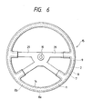
- Figs. 1, 2, 3, 4, 5 and 6 are for describing a method which is one of the embodiments and in which a steering wheel 15 is manufactured.
- the core 9 of the steering wheel is composed of a boss 19, an annular portion 1 located around the boss and having a groove 2 having a nearly U-shaped cross section and extending in the circumferential direction of the annular portion, and spokes 29 coupling the boss and the annular portion to each other, as shown in Fig. 1.
- the annular portion 1 has two walls 7 and 8 defining the groove 2 between them.
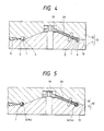
- the wall 8 faces a gate 5 provided at the separation surfaces 13 of a molding die unit 12 consisting of an upper and a lower molding dies 10 and 11, and has a notched part 8a which is notched to be smaller in height than the other part 8b of the wall and is located near the gate 5, as shown in Fig. 2.
- the core 9 is set in the molding cavity 4 of the molding die unit 12, the top of the notched part 8a of the wall 8 is located below the separation surfaces 13 of the upper and the lower molding dies 10 and 11.
- the method of manufacturing the steering wheel, in which a coating layer 14 is molded on the core 9, is described step by step from now on.
- the upper and lower molding dies 10 and 11 of the molding die unit 12, which has the gate 5 formed at the separation surfaces 13 of the dies and communicating with the molding cavity 4, are opened from each other.
- the core 9 is set in the lower molding die 11 so that the outer most part 3 of the groove 2 of the annular portion 1 of the core is located as the top of the groove, the notched part 8a of the wall 8 of the annular portion faces the gate 5 of the molding die unit 12, and the top of the notched part is located in the molding cavity 4 and below the separation surfaces 13 of the die unit, as shown in Figs. 3 and 4.
- the coating layer molding step of the method after that, the upper and the lower molding dies 10 and 11 are closed on each other, an urethane resin 6 is injected into the molding cavity 4 through the gate 5 so that the coating layer 14 is molded of the urethane resin on the core 9.
- the annular portion 1 of the core of a steering wheel is made of three walls 7, 8 and 16, as shown in Figs. 7 and 8.
- the wall 8, which faces the gate 5 of a molding die unit 12, and the central wall 16 have notched parts 8a and 16a, which are located near the gate.
- the parts 8a and 16a are notched to be smaller in height than the other wall 7 facing the boss of the core.
- the notched part 16a of the central wall 16 is made smaller in height than that 8a of the wall 8 but larger in circumferential length than the latter to cause a synthetic resin 6 to more efficiently flow into the narrow grooves 2 of the annular portion 1 of the core.
Landscapes
- Engineering & Computer Science (AREA)
- Mechanical Engineering (AREA)
- Manufacturing & Machinery (AREA)
- Chemical & Material Sciences (AREA)
- Combustion & Propulsion (AREA)
- Transportation (AREA)
- Injection Moulding Of Plastics Or The Like (AREA)
- Moulds For Moulding Plastics Or The Like (AREA)
- Steering Controls (AREA)
Applications Claiming Priority (2)
| Application Number | Priority Date | Filing Date | Title |
|---|---|---|---|
| JP2004959A JP2652254B2 (ja) | 1990-01-13 | 1990-01-13 | ステアリングホイールの製造方法 |
| JP4959/90 | 1990-01-13 |
Publications (3)
| Publication Number | Publication Date |
|---|---|
| EP0439033A2 true EP0439033A2 (fr) | 1991-07-31 |
| EP0439033A3 EP0439033A3 (en) | 1992-03-11 |
| EP0439033B1 EP0439033B1 (fr) | 1995-03-29 |
Family
ID=11598122
Family Applications (1)
| Application Number | Title | Priority Date | Filing Date |
|---|---|---|---|
| EP91100325A Expired - Lifetime EP0439033B1 (fr) | 1990-01-13 | 1991-01-11 | Procédé pour fabriquer un volant de direction |
Country Status (6)
| Country | Link |
|---|---|
| EP (1) | EP0439033B1 (fr) |
| JP (1) | JP2652254B2 (fr) |
| KR (1) | KR950008993B1 (fr) |
| CA (1) | CA2034029C (fr) |
| DE (1) | DE69108417T2 (fr) |
| ES (1) | ES2073043T3 (fr) |
Families Citing this family (2)
| Publication number | Priority date | Publication date | Assignee | Title |
|---|---|---|---|---|
| GB2409715A (en) † | 2003-12-31 | 2005-07-06 | Autoliv Dev | Moulding of a plastic steering wheel integral with a metal frame by injecting a propellant to form a cavity |
| KR100939546B1 (ko) | 2009-08-17 | 2010-02-03 | 안병철 | 핸들커버 제조금형 |
Family Cites Families (3)
| Publication number | Priority date | Publication date | Assignee | Title |
|---|---|---|---|---|
| JPS5237936U (fr) * | 1975-07-31 | 1977-03-17 | ||
| JPS61249869A (ja) * | 1985-04-26 | 1986-11-07 | Toyoda Gosei Co Ltd | ステアリングホイールの製造方法 |
| JPH0621812Y2 (ja) * | 1986-07-30 | 1994-06-08 | 日本プラスト株式会社 | ステアリングホイ−ル |
-
1990
- 1990-01-13 JP JP2004959A patent/JP2652254B2/ja not_active Expired - Lifetime
-
1991
- 1991-01-08 KR KR1019910000145A patent/KR950008993B1/ko not_active Expired - Fee Related
- 1991-01-11 CA CA002034029A patent/CA2034029C/fr not_active Expired - Lifetime
- 1991-01-11 EP EP91100325A patent/EP0439033B1/fr not_active Expired - Lifetime
- 1991-01-11 ES ES91100325T patent/ES2073043T3/es not_active Expired - Lifetime
- 1991-01-11 DE DE69108417T patent/DE69108417T2/de not_active Expired - Fee Related
Also Published As
| Publication number | Publication date |
|---|---|
| KR950008993B1 (ko) | 1995-08-10 |
| JPH03213462A (ja) | 1991-09-18 |
| DE69108417D1 (de) | 1995-05-04 |
| KR910014271A (ko) | 1991-08-31 |
| CA2034029A1 (fr) | 1991-07-14 |
| CA2034029C (fr) | 1994-07-05 |
| EP0439033A3 (en) | 1992-03-11 |
| JP2652254B2 (ja) | 1997-09-10 |
| DE69108417T2 (de) | 1996-01-04 |
| ES2073043T3 (es) | 1995-08-01 |
| EP0439033B1 (fr) | 1995-03-29 |
Similar Documents
| Publication | Publication Date | Title |
|---|---|---|
| EP0625089B1 (fr) | Moulage par injection d'un objet en plastique comprenant une nervure creuse | |
| KR102629317B1 (ko) | 전체 두께 리브 섹션을 갖는 가요성 골프 그립 및 그의 제조 방법 | |
| US5204043A (en) | Method of manufacturing steering wheel | |
| US5714104A (en) | Method of molding FRP parts | |
| EP0439033B1 (fr) | Procédé pour fabriquer un volant de direction | |
| FR2709673B1 (fr) | Procédé pour la fabrication d'un ski en forme. | |
| JPH0542557A (ja) | 中空成形法 | |
| JPH05162174A (ja) | チューブ容器の製造方法およびチューブ容器 | |
| US5417916A (en) | Injection molding method utilizing primary and secondary resin flow paths | |
| US4489849A (en) | Pivot assembly | |
| JP3180380B2 (ja) | 中空成形体 | |
| JPH07314499A (ja) | 射出成形金型 | |
| JPS58116139A (ja) | 異色部分を有する合成樹脂成形品の製造方法 | |
| JPS6010822Y2 (ja) | 合成樹脂の発泡成形用型 | |
| JP3062141B2 (ja) | マッドガードの製造方法 | |
| JP3527026B2 (ja) | 広口壜のプラグ付き中栓とその成形用金型 | |
| JPS6012781B2 (ja) | 発光ダイオ−ド素子の樹脂封止成形方法及びその金型装置 | |
| CA2259114A1 (fr) | Procede de production d'elements de structures | |
| JPS61207612A (ja) | Frp製ヘルメツトの製造方法 | |
| JPS6050127B2 (ja) | 蓄電池電槽の製造方法 | |
| JPH01269511A (ja) | 樹脂成形品の製造方法 | |
| HK40010309B (zh) | 制造模型车身的方法 | |
| JPS641054Y2 (fr) | ||
| JPH0137249B2 (fr) | ||
| JPS594092B2 (ja) | 漁撈用錘の成形方法 |
Legal Events
| Date | Code | Title | Description |
|---|---|---|---|
| PUAI | Public reference made under article 153(3) epc to a published international application that has entered the european phase |
Free format text: ORIGINAL CODE: 0009012 |
|
| 17P | Request for examination filed |
Effective date: 19910111 |
|
| AK | Designated contracting states |
Kind code of ref document: A2 Designated state(s): DE ES FR GB IT SE |
|
| PUAL | Search report despatched |
Free format text: ORIGINAL CODE: 0009013 |
|
| AK | Designated contracting states |
Kind code of ref document: A3 Designated state(s): DE ES FR GB IT SE |
|
| 17Q | First examination report despatched |
Effective date: 19931115 |
|
| GRAA | (expected) grant |
Free format text: ORIGINAL CODE: 0009210 |
|
| AK | Designated contracting states |
Kind code of ref document: B1 Designated state(s): DE ES FR GB IT SE |
|
| REF | Corresponds to: |
Ref document number: 69108417 Country of ref document: DE Date of ref document: 19950504 |
|
| ITF | It: translation for a ep patent filed | ||
| ET | Fr: translation filed | ||
| REG | Reference to a national code |
Ref country code: ES Ref legal event code: FG2A Ref document number: 2073043 Country of ref document: ES Kind code of ref document: T3 |
|
| PLBE | No opposition filed within time limit |
Free format text: ORIGINAL CODE: 0009261 |
|
| STAA | Information on the status of an ep patent application or granted ep patent |
Free format text: STATUS: NO OPPOSITION FILED WITHIN TIME LIMIT |
|
| 26N | No opposition filed | ||
| PGFP | Annual fee paid to national office [announced via postgrant information from national office to epo] |
Ref country code: SE Payment date: 19980116 Year of fee payment: 8 |
|
| PGFP | Annual fee paid to national office [announced via postgrant information from national office to epo] |
Ref country code: ES Payment date: 19980129 Year of fee payment: 8 |
|
| PG25 | Lapsed in a contracting state [announced via postgrant information from national office to epo] |
Ref country code: ES Free format text: LAPSE BECAUSE OF NON-PAYMENT OF DUE FEES Effective date: 19990112 Ref country code: SE Free format text: LAPSE BECAUSE OF NON-PAYMENT OF DUE FEES Effective date: 19990112 |
|
| REG | Reference to a national code |
Ref country code: ES Ref legal event code: FD2A Effective date: 20011010 |
|
| REG | Reference to a national code |
Ref country code: GB Ref legal event code: IF02 |
|
| PG25 | Lapsed in a contracting state [announced via postgrant information from national office to epo] |
Ref country code: IT Free format text: LAPSE BECAUSE OF NON-PAYMENT OF DUE FEES Effective date: 20050111 |
|
| PGFP | Annual fee paid to national office [announced via postgrant information from national office to epo] |
Ref country code: DE Payment date: 20090108 Year of fee payment: 19 |
|
| PGFP | Annual fee paid to national office [announced via postgrant information from national office to epo] |
Ref country code: GB Payment date: 20090107 Year of fee payment: 19 |
|
| PGFP | Annual fee paid to national office [announced via postgrant information from national office to epo] |
Ref country code: FR Payment date: 20090113 Year of fee payment: 19 |
|
| GBPC | Gb: european patent ceased through non-payment of renewal fee |
Effective date: 20100111 |
|
| REG | Reference to a national code |
Ref country code: FR Ref legal event code: ST Effective date: 20100930 |
|
| PG25 | Lapsed in a contracting state [announced via postgrant information from national office to epo] |
Ref country code: FR Free format text: LAPSE BECAUSE OF NON-PAYMENT OF DUE FEES Effective date: 20100201 |
|
| PG25 | Lapsed in a contracting state [announced via postgrant information from national office to epo] |
Ref country code: DE Free format text: LAPSE BECAUSE OF NON-PAYMENT OF DUE FEES Effective date: 20100803 |
|
| PG25 | Lapsed in a contracting state [announced via postgrant information from national office to epo] |
Ref country code: GB Free format text: LAPSE BECAUSE OF NON-PAYMENT OF DUE FEES Effective date: 20100111 |