EP0440143A2 - Système d'illumination pour caméra - Google Patents
Système d'illumination pour caméra Download PDFInfo
- Publication number
- EP0440143A2 EP0440143A2 EP19910101091 EP91101091A EP0440143A2 EP 0440143 A2 EP0440143 A2 EP 0440143A2 EP 19910101091 EP19910101091 EP 19910101091 EP 91101091 A EP91101091 A EP 91101091A EP 0440143 A2 EP0440143 A2 EP 0440143A2
- Authority
- EP
- European Patent Office
- Prior art keywords
- imprint
- seal
- registered
- sample
- ratio
- Prior art date
- Legal status (The legal status is an assumption and is not a legal conclusion. Google has not performed a legal analysis and makes no representation as to the accuracy of the status listed.)
- Withdrawn
Links
Images


Classifications
-
- G—PHYSICS
- G03—PHOTOGRAPHY; CINEMATOGRAPHY; ANALOGOUS TECHNIQUES USING WAVES OTHER THAN OPTICAL WAVES; ELECTROGRAPHY; HOLOGRAPHY
- G03B—APPARATUS OR ARRANGEMENTS FOR TAKING PHOTOGRAPHS OR FOR PROJECTING OR VIEWING THEM; APPARATUS OR ARRANGEMENTS EMPLOYING ANALOGOUS TECHNIQUES USING WAVES OTHER THAN OPTICAL WAVES; ACCESSORIES THEREFOR
- G03B15/00—Special procedures for taking photographs; Apparatus therefor
- G03B15/02—Illuminating scene
- G03B15/03—Combinations of cameras with lighting apparatus; Flash units
- G03B15/05—Combinations of cameras with electronic flash apparatus; Electronic flash units
-
- G—PHYSICS
- G03—PHOTOGRAPHY; CINEMATOGRAPHY; ANALOGOUS TECHNIQUES USING WAVES OTHER THAN OPTICAL WAVES; ELECTROGRAPHY; HOLOGRAPHY
- G03B—APPARATUS OR ARRANGEMENTS FOR TAKING PHOTOGRAPHS OR FOR PROJECTING OR VIEWING THEM; APPARATUS OR ARRANGEMENTS EMPLOYING ANALOGOUS TECHNIQUES USING WAVES OTHER THAN OPTICAL WAVES; ACCESSORIES THEREFOR
- G03B15/00—Special procedures for taking photographs; Apparatus therefor
- G03B15/02—Illuminating scene
- G03B15/03—Combinations of cameras with lighting apparatus; Flash units
- G03B15/035—Combinations of cameras with incandescent lamps
-
- G—PHYSICS
- G03—PHOTOGRAPHY; CINEMATOGRAPHY; ANALOGOUS TECHNIQUES USING WAVES OTHER THAN OPTICAL WAVES; ELECTROGRAPHY; HOLOGRAPHY
- G03B—APPARATUS OR ARRANGEMENTS FOR TAKING PHOTOGRAPHS OR FOR PROJECTING OR VIEWING THEM; APPARATUS OR ARRANGEMENTS EMPLOYING ANALOGOUS TECHNIQUES USING WAVES OTHER THAN OPTICAL WAVES; ACCESSORIES THEREFOR
- G03B17/00—Details of cameras or camera bodies; Accessories therefor
- G03B17/02—Bodies
- G03B17/12—Bodies with means for supporting objectives, supplementary lenses, filters, masks, or turrets
Definitions
- the present invention relates to a lighting system, irradiates light to the object to be photographed.
- an irradiation system is settled near a camera to take a photograph of a shape by CCD camera in the case of using shape (seal-imprint) verification to judge if a sealed imprint is the same as registered one.
- This irradiation system possesses plural light-supplying lamp to irradiate light from upper slanting direction of an imprint as disclosed, for example in the publication No. Sho 59-49666.
- the light irradiated from such a light-supplying lamp does not reflect the vermilion imprint substantially but reflects white paper.
- the imprint is taken a photograph by CCD camera and performed the processing for imprint verification after inputted to the computer of imprint verification system.
- the present invention has an object to provide a lighting system for irradiating even light to whole imprint and photographing the imprint more accurately.
- the lighting system according to the present invention has the characteristics of comprising a lighting system for camera characterized in comprising light irradiation means which possesses plural luminous objects arranged circularly in the center of camera lens, and cylindrical shield parts to restrain light from outside arranged between the camera and an object to be photographed.
- Fig. 1 shows a sectioned diagram of the first embodiment of the present invention.
- Fig. 2 shows a block diagram of outline structure of a seal-imprint verification system applied the present invention.
- Fig. 3 shows a diagram of lighting structure from diagonal angle.
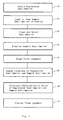
- Fig. 4 shows a diagram of outline process for verification of seal-imprints.
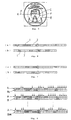
- Fig. 5 shows an example of seal-imprint.
- Fig. 6 (a) shows pixels along the outside circle of registered seal-imprint.
- Fig. 6 (b) shows pixels along the inside circle of registered seal-imprint.
- Fig. 7 (a) shows pixels along the outside circle of sample seal-imprint.
- Fig. 7 (b) shows pixels along the inside circle of sample seal-imprint.
- Fig. 8 is a diagram to overlap pixel data of sample seal-imprint by shifting 1 pixel on that of registered one.
- Fig. 9 (a) shows parallel movement of sample seal-imprint in up and down direction on registered seal-imprint.
- Fig. 9 (b) shows parallel movement of sample seal-imprint in right and left direction on registered seal-imprint.
- Fig. 10 shows 3x3 area for searching the location with the maximum identification ratio between sample seal-imprint and registered one.
- Fig. 11 shows a sample seal-imprint and registered one to be swelled.
- Fig. 12 shows clustering on standard data in identification ratio of sample seal-imprint corresponding to registered one.
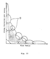
- Fig. 13 shows the relationship between blur ratio and faint, scratchy ratio in the case that the number of clusters is 12.
- Fig. 14 shows the relationship between blur ratio and faint, scratchy ratio in the case that the number of clusters is 6.
- Fig. 2 shows the structure of outline of seal-imprint verification system. It comprises seal-imprint input system 10, image processing system 30, host computer 40, seal-imprint image display system 50 and truth judgment system 60.
- Seal-imprint input system 10 photographs seal-imprint.
- the photographed image data is transmitted to image processing system 30.
- image processing system 30 the characteristics value of seal-imprint is calculated (seal-imprint area, for example) by performing various image processing.
- Image processing system 30 works according to the order of host computer 40 and outputs the data of characteristics value of seal-imprint to host computer 40.
- Host computer 40 controls whole of the present system. Simultaneously, it evaluates the characteristic value from image processing system 30 and judges whether the seal-imprint agrees with the registered one or not.
- Seal-imprint display system 50 comprises CRT connected to image processing system 30 and displays a seal-imprint.
- Truth judgment system 60 comprises CRT connected to host computer 40 and displays the result of judgment if a seal-imprint agrees with the registered one or not.
- Seal-imprint input system 10 comprises a CCD camera 11 as shown in Fig. 3 whose lens is received to mirror tube 12 which runs to downward from the main body.
- CCD camera 11 is confronted by paper 13 on which sealed imprint.
- CCD camera 11 can move parallelly to paper 13 and turn round in the center of the lens.
- cylindrical irradiation mechanism 21 is settled, which comprises a lot of optical fibers 23 as shown in Fig. 4.
- Optical fiber 23 is connected to light source (not indicated) which emits light by direct current such as halogen lamp.
- Cylindrical light shield material 14 is settled between camera 11 and paper 13.
- Light shield material 14 is put on paper 13, whose upper edge is close to the body of camera 11 so as not to be irradiated by light from outside as little as possible.
- Inner circuit of light-shield material is covered by film 15 which reflects light such as aluminum foil.
- Fig. 4 shows the structure of irradiation mechanism 21.
- Irradiation mechanism 21 comprises a lot of optical fibers 23 in circular support material 22: these optical fibers 23 are arranged circularly in the center of lens-barrel 12.
- Blue filter 24 transparent to light is put such as cellophane circular in the center of lens on the top part of each optical fiber 23, that is the bottom part of support material 22.
- the reason that filter 24 transparent to light is blue is that it is contrasty between seal-imprint and background paper because a seal-imprint to be photographed is vermilion.
- Support material 22 is fitted with lens-barrel 12 of camera 11 by screws 25.
- the lighting system in the present invention comprises circular irradiation mechanism 21 surrounding the lens of camera 11 and light-shield material 14 controlling irradiation of light from outside.
- Irradiating mechanism 21 is constructed to obtain a clear seal-imprint by irradiating light to paper 13 evenly and irradiating blue light through blue cellophane (translucent filter) 24. It prevents entering light from outside by light shield material and is constructed to irradiate more evenly to seal-imprint by reflecting film 15. Therefore, it is possible to photograph an imprint sealed on paper 13 clearly and accurately as a whole: the precision of seal-imprint can be improved as a consequence.
- Fig. 5 shows the outline of the process of seal-imprint verification. The outline is explained first below.
- step S0 a registered imprint is obtained. It is obtained by photographing sealed imprint by CCD camera 11: the method is the same as in step S1, S2, S3 and S5 described later.
- step S1 seal-imprint is inputted to display for comparing with the registered one. That is, photographing sealed imprint on paper by CCD camera 11, seal-imprint is displayed on CRT of seal-imprint display system 50.
- step S2 seal-imprint is extracted by erasing background outside of seal-imprint and noise in sample one.
- step S3, binarizing sample seal-imprint a monochrome gray-level image is converted into black and white image.
- step 4 it is judged roughly if a sample seal-imprint is the same as registered one from the size and the number of pixels of the seal-imprint, or not.
- step 4 seal-imprint verification is concluded on the point of the judgment.
- sample seal-imprint is placed upon registered one by rotation or parallel movement of sample one.
- step S6 the truth of the sample is judged in detail according to the characteristics value. Characteristics value here means the ratio of registered to sample seal-imprint, identification ratio, blur ratio and faint, patchy ratio. The area ratio, identification ratio, blue ratio, and faint, patchy ratio are defined later.
- step S0 The processing in step S0 is described later because it is the same as in step S1, S2, S3 and S5 for sample seal-imprint to obtain exact registered seal-imprint with least blur or faint, patchy part. It is provided that registered seal-imprint is obtained already in i) to vii) below.
- Sample seal-imprint is photographed by CCD camera 11 with contrasty state between the sample and paper by irradiating blue light, as explained referring from Fig. 1 to Fig. 3.
- the seal-imprint obtained in this way is inputted to image processing system 30, executed A/D conversion, and displayed on CRT of seal-imprint display system 50.
- the monotonous color of black and white is displayed conversely so as seal-imprint to be white and background to be black in order to be easy to observe human eyes on CRT.
- step S2 smoothing is performed by replacing the mean of brightnesses of each pixel in the area of 3x3 for example into the brightness of center pixel in the area and consequently, noises in an image become vague.
- an edge of seal-imprint is sharpened by Sobel operator.
- any method can be used for emphasizing an edge of an image except Sobel operator.
- the image obtained in this way is binarized after deciding threshold by discrimination analysis method or other methods, and simultaneously, swelling is performed 5 times by one pixel for each time.
- the characters in the seal-imprint is connected in one line even when blur, faint or patchy part are included, and noises also swell and become large.
- the seal-imprint is labeled at every connected diagram. The smaller number is added on the labeling. Therefore, it is presumed that the diagram with the largest number comprises at least seal-imprint, and that with smaller number than it is noise. Only the diagrams with the largest number are left and others are erased.
- Perpendicular and horizontal fillet diameters are calculated in the state and rough area of seal-imprint is decided according to the fillet diameters.
- the parts outside of the area are all judged as background and erased recognizing all of brightness points (pixels) to be noises (that is, brightness is made to be "0").
- the area obtained in step S2 is placed upon the image of seal-imprint obtained in step S1. That is, the image of seal-imprint obtained in step S1 is surrounded by the area obtained in step S2: the brightness outside of the area is "0".
- Concerning to the density distribution in whole of the image of CRT displaying the seal-imprint image the ratio of scattering within a class to that between classes (scattering ratio) is calculated and the threshold on which scattering ratio is maximum is calculated (discrimination analysis method).
- the image of seal-imprint is binarized using the threshold and converted into black and white colors. Other methods such as mode method can be adopted for threshold determination method.
- the area of sample seal-imprint and that of registered seal-imprint are compared and also both maximal diameters are compared. Area is compared by comparing the pixels of seal-imprint in each image. When there is a lot of difference between the area of sample seal-imprint and that of registered one, the sample is judged to be different from registered one and seal-imprint verification is concluded without executing steps from S5 to S7. On the other hand, when there is (a) little difference between them, it is judged that sample seal-imprint is possible to be the same as registered one and step S5 and after it are executed.
- the value for judging if there is a lot of difference between the area or between the maximal diameters is decided by the statistical calculation below.
- the maximal diameter placing sample image upon registered image in CRT, how many pixels are spread outside of registered seal-imprint is calculated on all samples. Assuming that the maximal value among then is ⁇ , the maximal diameter of registered seal-imprint is ⁇ , and the maximal diameter of sample seal-imprint is ⁇ , ⁇ adopts ( ⁇ +2 ⁇ ) as the standard value. When ⁇ is larger than ( ⁇ +2 ⁇ ), the sample is judged to be different from registered one. The coefficient of ⁇ can be also changed according to the necessity.
- Fig. 7 (a) is an example of 1-dimensional spectrum of outside circle E and shows each pixel on the circle on scanning clockwise from standard line K.
- hatched part I shows the existence of the pixel of registered seal-imprint and while part J shows the inexistence of the pixel of registered one.
- Fig. 7 (b) shows 1-dimensional spectrum of inside circle F.
- Fig. 8 (a) shows an example of 1-dimensional spectrum of outside circle
- Fig. 8 (b) shows an example of 1-dimensional spectrum of inside circle.
- 1-dimensional spectrum A on the outside circle of registered seal-imprint and 1-dimensional spectrum B0 on the outside circle of sample seal-imprint are placed upon and compared each other by corresponding pixel as shown in Fig. 8. That is, as to spectrums A and B0, the out of parts in agreement are obtained by exclusive-or operation. In the figure, the out of the pixels in agreement are shown by arrows with regard to the relationship between spectrums A and B0. The disagreement ratio is calculated by dividing the number of pixels with arrows, that is the number of pixels out of agreement by the number of all the pixels in circle E of registered seal-imprint.
- spectrum B1 is obtained, which is shifted 1 pixel to the right from the spectrum of sample seal-imprint.
- the disagreement ratio between spectrum B1 and spectrum A of registered seal-imprint is calculated by the method described above. In the same way, disagreement ratio between A and the shifted by 1 pixel from the spectrum of sample seal-imprint is obtained sequentially. This operation is executed until shifted spectrum is Bn (n is the number of pixels of a circle).
- the angle for the sample seal-imprint to be rotated is obtained for the comparison with registered seal-imprint. That is, the value calculated by the formula is the rotation angle with the outside circle E as the standard.
- the angle to be rotated for the sample seal-imprint is calculated with the inside circle F as the standard.
- the sample seal-imprint is moved parallelly in order for identification ratio between the sample and registered seal-imprint to be the maximum.
- the parallel movement is explained here referring Fig. 9 (a), (b), and Fig. 10.
- solid line M shows fillet diameters (horizontal and vertical outlines) of registered seal-imprint.
- Chain line with one dot P and chain line with two dots N show horizontal and vertical center lines of registered seal-imprint, a fillet diameter of sample seal-imprint, respectively.
- sample seal imprint is placed by taking the position for the center of the upper horizontal fillet diameter of sample seal imprint to be 5 pixels above the upper horizontal fillet diameter of registered seal-imprint. The identical number of pixels between sample seal-imprint and registered one is counted. Displacing sample seal-imprint on the position 3 pixels below the registered one, the identical number of pixels is counted. In the same way, moving sample seal-imprint to the position 3 pixels below, the identical number of pixels is counted; and the present processing is repeated until the center of horizontal fillet diameter N2 on lower side of sample seal-imprint comes 5 pixels below the center of horizontal fillet diameter M2 on lower side of registered seal-imprint.
- the identical number of pixels between sample seal-imprint and registered one is counted by placing sample seal-imprint on the location that the center of vertical fillet diameter N3 on left side of sample seal-imprint is 5 pixels left from the center of vertical fillet diameter M3 on left side of registered seal-imprint.
- the identical number of pixels is calculated again by displacing rightward by 3 pixels from the registered seal-imprint.
- displacing sample seal-imprint rightward by 3 pixels the identical number of pixels is counted until the center of vertical fillet diameter N4 on the right side of sample seal-imprint comes a position rightward by 5 pixels from the center of vertical fillet diameter M4 on the right side of registered seal-imprint.
- the location "a" of sample seal-imprint with the maximal identification ratio is obtained among them moved parallelly upper, below, left and right.
- sample seal-imprint is moved with respect to 8 pixels in area Q which is the neighborhood of 1 pixel around in the center of "a" with the most highest identification ratio, and the identification ratio between the pixels in sample seal-imprint and the registered one on each place.
- sample seal-imprint When there is a location with identification ratio lager than that on location "a" from location "b” to “i”, sample seal-imprint is moved on the location with the largest identification ratio. If “e” is such a place, sample seal-imprint is moved from “j” on 1 pixel neighborhood to "k", “l”, “m” and “n” as the center to be “e”; and identification ratio on each location is calculated. When the identification ratio on “e” is larger than any value from that on “j” to "n”, parallel movement of sample seal-imprint is concluded on “e”.
- the movement quantity of right or left is provided to be X1, and upper or lower, to be Y1.
- the movements are repeated again and fine adjustment for positioning is executed.
- the centers of circles E and F are the center of fillet diagram of registered seal-imprint as to a sample seal-imprint. Therefore, as to the rotation of sample seal-imprint, the identification ratio between it and registered one is calculated by rotating it on the axis of the center of fillet diagram of the registered one. Parallel displacement is calculated from the center.
- the rotating angle, movement distance in rightward or leftward, and movement distance in upper or lower direction are assumed to be ⁇ 2, X2 and Y2.
- 2 kinds of angles and a parallel movement distance are calculated by executing rotation and parallel movement twice respectively.
- 2 of rotation angles ⁇ 1 and ⁇ 2 are added to the angles above and the value after the addition is the rotation angle to give to sample seal-imprint finally.
- rightward or leftward parallel movement quantity X1 and X2 are added together, and also, upward or downward parallel movement quantity Y1 and Y2 are added together: these values after the addition are the parallel movement quantities of sample seal-imprint in the right or left direction and upper or lower direction.
- the binarized sample seal-imprint obtained in step S3 is placed on registered one by rotating or moving parallelly as the quantity after addition in below. ( ⁇ 1+ ⁇ 2), (X1+X2), (Y1+Y2)
- step S6 when at least one in 9 area ratios is out of the range of area ratios used in step S4, the processing is concluded then. It shows that the processing is performed to check the condition of losses, and the verification is not performed for what with too many losses.
- the number of division and the threshold of area ratio in each small part can be changed according to the necessity.
- step S6 characteristics values of registered seal-imprint and sample one.
- the characteristics values mean area ratio to check the characteristics in general situation of a seal-imprint, identification ratio (master), identification ratio (itself), blur ratio (master), blur ratio (itself), faint and patchy ratio (master), faint and patchy ratio (itself), and the coefficient of faint and patchy ratio on swelling to check in detail the difference of stroke in a character included in a seal-imprint. These are defined as below.
- the number of pixels with agreement is "the total number of overlapped pixels when a sample seal-imprint is placed on the registered one"; the number of pixels with blur is “the total number of pixels in sample seal-imprint when a sample seal-imprint is placed on the registered one”; the number of faint and patchy pixels is “the total number of pixels without overlapping when a sample seal-imprint is placed on the registered one”.
- the number of sample seal-imprint and that of the registered one are assumed to be S and T, respectively.
- the coefficient of swelling, faintness and scratchiness is calculated by the next formula after swelling registered seal-imprint as 1 pixel 8 times and calculating the number of blur pixels included each swelling layer in the state of overlapping the registered seal-imprint and sample 80.
- Coefficient of Swelling and Blur in n-th Layer (number of pixels with agreement + number of blur pixels from swelled first layer to swelled n-th layer)/(number of pixels in sample seal-imprint) x 100 n is from 1 to 8. Swelled and blur coefficient is calculated in each swelled layer from the first to the eighth. (cf. Fig. 11)
- the following data are to be what percent around when the area ratio is 80% considering the clustering: identification ratios (master and itself), blur ratios (master and itself), faint and scratchy ratio (master and itself), characteristics values on swelling blur ratio coefficients from 1 to 8.
- a sample seal imprint is judged to be corresponding to the registered one when the characteristics value is within the certain range: it is not judged to be corresponding to the registered one when the characteristics value is out of the range.
- the judgment of characteristics values is constructed from 3 units, that is, unit 1 which clusters with the data of the identification ratios of master and itself, unit 2 which clusters with the data of the area ratio calculated by dividing a sample seal-imprint by the registered one and unit 3 which clusters with the data of blur ratios of master and itself and faint, scratchy ratios of master and itself.
- unit 1 clustering the characteristics values from the data of identification ratios of master and itself, the following data of the rest characteristics value is examined. That is, area ratio, blur ratios of master and itself, faint and scratchy ratios of master and itself, and each swelling blur coefficient from the first layer to the eighth layer.
- clustering the characteristics values from the data of area ratio the following data of the rest is examined. That is, identification ratios of master and itself, blur ratios of master and itself, faint and scratchy ratios of master and itself, and each swelling blur coefficient from the first to the eighth layer.
- clustering the characteristics values from the data of blur ratios of master and itself, faint and scratchy ratios of master and itself, and area ratio the following data of the rest is examined. That is, area ratio, identification ratios of master and itself, and each swelling blur coefficient from the first to the eighth layer.
- Fig. 12 shows the standard data generally and approximately.
- Fig. 12 it is shown that there is a certain relationship between identifications of master and itself, and there are 6 clusters from C1 to C6.
- point G shows the relationship between both of identification ratios of the sample seal-imprint in verification
- the relationship between the sample seal-imprint and the registered one in verification now is C4 in the fourth cluster, according to the examination above.
- the fourth cluster C4 it is judged if area ratio, blur ratios (master and itself), faint and scratchy ratios (master and itself) are judged if they are within the standard data or not.
- mean value and standard deviation are assumed to be those in TABLE 1 below.
- blur ratios and faint and scratchy ratios in sample seal-imprint and registered one in verification are judged if they are within the range that 3 times of standard deviation with the mean value in the center or not (that is, it is judged if they are within the range of (mean value)+-3x(standard deviation)). For example, when area ratio in 122.6, blur ratio (master) is 22.6, blur ratio (itself), faint and scratchy ratio (master) is 4.3, and faint and scratchy ratio (itself) is 3.9, they are all in the range above and the sample seal-imprint is supposed to be corresponding to registered seal-imprint. When at least one of them is out of the range, however, the sample seal-imprint in verification is not judged to be corresponding to the registered one.
- swelling blur coefficient is examined. For example as to the n-th layer in Fig. 11, assuming line 83 is adopted, the swelling blur coefficient is calculated, as shown in step S6, by adding the total number of pixels in layer 81 to 83 to the number of pixels of identification, and dividing the result by all the number of pixels in sample seal-imprint, then multiplying the result by 100.
- the coefficient calculates the standard deviation which shows the mean value and the distribution in every cluster and in every layer from the first to the eighth. For example, swelling blur coefficient in cluster C4 are calculated as in TABLE 2.
- the judgment in unit 2 is executed for next clustering, from area ratio in the same way as in unit 1.
- Characteristic values are executed if they are within the standard values: that is, identification ratios (master and itself), blur ratios (master and itself), faint and scratchy ratios (master and itself), swelling blur coefficients from the first to the eighth layer.
- identification ratios (master and itself), blur ratios (master and itself), and faint and scratchy ratios (master and itself) are within the standard value
- the sample seal-imprint is judged to be the same as the registered one.
- the sample seal-imprint is judged to be different from the registered one.
- swelling blur coefficient is examined. The examination is similar to that in unit 1.
- the sample seal-imprint is judged to be the same as the registered one.
- the sample seal-imprint is judged to have the possibility of no sameness as the registered one.
- the judgment is completed from the general view, that is, area ratio, identification ratios of master and itself, blur ratios of master and itself, faint and scratchy ratios of master and itself, and swelling blur coefficient from the first to the eighth layers for detailed standard judgment of a difference of character to construct the seal-imprint.
- Final judgment is executed as follows.
- step S7 precise truth judgment is completed in step S7.
- the number of clusters used in the judgment is selected according to the judgment precision. It is described referring to Figs. 13 and 14.
- FIGs show the relationship between blur ratio of master and faint, scratchy ratio of master in the case that a sample seal-imprint corresponds to the registered one.
- Each point shows the data of blur ratio and faint, scratchy ratio, and ellipse D shows clusters.
- the abscissa of the center point in each cluster is the mean value of blur ratio of data in the cluster, and the ordinate is the mean value of faint, scratchy ratio of data in the cluster.
- the size of ellipse is decided by taking major diameter or minor diameter with the length of 3 times of standard deviation ⁇ in plus and minus directions in the middle of the mean value of blur ratio, and by taking major diameter or minor diameter with the length of 3 times of standard deviation ⁇ in plus and minus directions in the middle of the mean value of faint and scratchy ratio.
- the first seal-imprint is photographed by CCD camera by the same way in step S1. That is, photographing it 32 times, gray-level image is obtained, which is performed accumulating addition on 32 of seal-imprints.
- An area is approximately decided by clearing image in the same way in step S2. Overlapping this area on the image obtained in step S1, the image outside of the area is deleted and the image inside of the area is binarized in the same way in step S3. Consequently, gray-level image and binarized image of the first seal-imprint are obtained.
- binarized image of the second seal-imprint is obtained by executing steps S1, S2 and S3 in the same way as to the first one. This is the second processed imprint.
- the second binarized imprint is overlapped on the first binarized imprint and their locations are adjusted by moving rotationally or parallelly as in step S5.
- the gray-level image of the second seal-imprint is moved with the angle and length obtained here on the gray-level image of the first seal-imprint.
- the gray-level images of the third and the fourth seal-imprint are overlapped on the gray-level of the first seal-imprint sequentially.
- the locations of the gray-level images from the first to the fourth seal-imprints are adjusted each other: the one obtained in such a way is the gray-level image of the registered seal-imprint.
- the binarized image of the registered seal-imprint is obtained by performing from step S2 to step S3.
- the present binarized one is the standard to verify sample seal-imprints.
- the number of overlapped seal-imprints is 4: any number will do in practical use.
Landscapes
- Physics & Mathematics (AREA)
- General Physics & Mathematics (AREA)
- Image Input (AREA)
- Collating Specific Patterns (AREA)
- Closed-Circuit Television Systems (AREA)
- Stroboscope Apparatuses (AREA)
- Studio Devices (AREA)
Applications Claiming Priority (2)
| Application Number | Priority Date | Filing Date | Title |
|---|---|---|---|
| JP18662/90 | 1990-01-29 | ||
| JP2018662A JPH03223972A (ja) | 1990-01-29 | 1990-01-29 | カメラの照明装置 |
Publications (2)
| Publication Number | Publication Date |
|---|---|
| EP0440143A2 true EP0440143A2 (fr) | 1991-08-07 |
| EP0440143A3 EP0440143A3 (en) | 1995-07-05 |
Family
ID=11977825
Family Applications (1)
| Application Number | Title | Priority Date | Filing Date |
|---|---|---|---|
| EP91101091A Withdrawn EP0440143A3 (en) | 1990-01-29 | 1991-01-28 | Lighting system for camera |
Country Status (4)
| Country | Link |
|---|---|
| US (1) | US5450291A (fr) |
| EP (1) | EP0440143A3 (fr) |
| JP (1) | JPH03223972A (fr) |
| KR (1) | KR910014740A (fr) |
Families Citing this family (22)
| Publication number | Priority date | Publication date | Assignee | Title |
|---|---|---|---|---|
| JPH1196362A (ja) * | 1997-09-17 | 1999-04-09 | Fujitsu Ltd | 印影照合装置 |
| US6912076B2 (en) | 2000-03-17 | 2005-06-28 | Accu-Sort Systems, Inc. | Coplanar camera scanning system |
| JP2003528410A (ja) * | 2000-03-17 | 2003-09-24 | アキュー − ソート・システムズ・インコーポレーテッド | 共面カメラスキャンシステム |
| US8042740B2 (en) | 2000-11-24 | 2011-10-25 | Metrologic Instruments, Inc. | Method of reading bar code symbols on objects at a point-of-sale station by passing said objects through a complex of stationary coplanar illumination and imaging planes projected into a 3D imaging volume |
| US7140543B2 (en) * | 2000-11-24 | 2006-11-28 | Metrologic Instruments, Inc. | Planar light illumination and imaging device with modulated coherent illumination that reduces speckle noise induced by coherent illumination |
| US7607581B2 (en) | 2003-11-13 | 2009-10-27 | Metrologic Instruments, Inc. | Digital imaging-based code symbol reading system permitting modification of system features and functionalities |
| US7464877B2 (en) | 2003-11-13 | 2008-12-16 | Metrologic Instruments, Inc. | Digital imaging-based bar code symbol reading system employing image cropping pattern generator and automatic cropped image processor |
| US7708205B2 (en) | 2003-11-13 | 2010-05-04 | Metrologic Instruments, Inc. | Digital image capture and processing system employing multi-layer software-based system architecture permitting modification and/or extension of system features and functions by way of third party code plug-ins |
| US7077319B2 (en) * | 2000-11-24 | 2006-07-18 | Metrologic Instruments, Inc. | Imaging engine employing planar light illumination and linear imaging |
| US7594609B2 (en) | 2003-11-13 | 2009-09-29 | Metrologic Instruments, Inc. | Automatic digital video image capture and processing system supporting image-processing based code symbol reading during a pass-through mode of system operation at a retail point of sale (POS) station |
| US7540424B2 (en) | 2000-11-24 | 2009-06-02 | Metrologic Instruments, Inc. | Compact bar code symbol reading system employing a complex of coplanar illumination and imaging stations for omni-directional imaging of objects within a 3D imaging volume |
| US6450655B1 (en) * | 2000-12-01 | 2002-09-17 | J.M. Canty Inc | Multi-port illuminating and viewing unit |
| US7604361B2 (en) * | 2001-09-07 | 2009-10-20 | Litepanels Llc | Versatile lighting apparatus and associated kit |
| US7331681B2 (en) * | 2001-09-07 | 2008-02-19 | Litepanels Llc | Lighting apparatus with adjustable lenses or filters |
| US6749310B2 (en) * | 2001-09-07 | 2004-06-15 | Contrast Lighting Services, Inc. | Wide area lighting effects system |
| US7513428B2 (en) | 2001-11-21 | 2009-04-07 | Metrologic Instruments, Inc. | Planar laser illumination and imaging device employing laser current modulation to generate spectral components and reduce temporal coherence of laser beam, so as to achieve a reduction in speckle-pattern noise during time-averaged detection of images of objects illuminated thereby during imaging operations |
| DE10354793A1 (de) * | 2002-11-23 | 2004-06-03 | Odas Gmbh | Verfahren zur fotografischen Aufnahme eines zylinderförmigen, insbesondere plattenförmigen Gegenstandes |
| JP3842257B2 (ja) * | 2003-08-28 | 2006-11-08 | Tdk株式会社 | 照明装置 |
| US7841533B2 (en) | 2003-11-13 | 2010-11-30 | Metrologic Instruments, Inc. | Method of capturing and processing digital images of an object within the field of view (FOV) of a hand-supportable digitial image capture and processing system |
| GB0407847D0 (en) * | 2004-04-07 | 2004-05-12 | Gekko Technology Ltd | Lighting apparatus |
| JP2006172080A (ja) * | 2004-12-15 | 2006-06-29 | Hitachi Global Storage Technologies Netherlands Bv | 光源のパラメータ設定方法及び識別記号の認識方法 |
| CN109363768A (zh) * | 2018-10-10 | 2019-02-22 | 南京诺源医疗器械有限公司 | 785nm波长光源近红外荧光造影手术引导系统 |
Family Cites Families (30)
| Publication number | Priority date | Publication date | Assignee | Title |
|---|---|---|---|---|
| GB191404187A (en) * | 1913-02-18 | 1914-05-07 | Philipp Georg Von Der Lippe | Improvements in Apparatus for use in the Photographic Production of Shadowless Pictures and Reliefs. |
| US2322032A (en) * | 1940-08-03 | 1943-06-15 | Albert J Kunze | Photographic apparatus |
| US2431825A (en) * | 1944-04-10 | 1947-12-02 | Gordon B Pollock | Medico-surgical photographic device |
| US2747459A (en) * | 1948-12-02 | 1956-05-29 | George L Morrison | Photographic apparatus |
| US2612824A (en) * | 1950-08-09 | 1952-10-07 | Jr Walter F Kroemmelbein | Television photographic device |
| DE1004920B (de) * | 1955-07-27 | 1957-03-21 | Flora Mannesmann Geb Nestler | Vorrichtung zur photographischen Aufnahme mit Roehrenblitzbeleuchtung |
| GB1230490A (fr) * | 1968-09-27 | 1971-05-05 | ||
| DE1914944A1 (de) * | 1969-03-24 | 1970-10-08 | Agfa Gevaert Ag | Mikrofilm-Schrittaufnahmegeraet |
| US3696720A (en) * | 1971-08-11 | 1972-10-10 | Integrated Controls Inc | Method and apparatus for photographing oscilloscope traces with conventional camera |
| US3834812A (en) * | 1973-11-23 | 1974-09-10 | Us Navy | Oscilloscope camera 35mm film recorder adapter |
| US3918810A (en) * | 1974-04-12 | 1975-11-11 | Venus Scient Inc | Ambient light excluding camera adapter with viewing hood |
| US4028728A (en) * | 1976-04-02 | 1977-06-07 | Western Electric Company, Inc. | Method of and video system for identifying different light-reflective surface areas on articles |
| JPS56122905A (en) * | 1980-03-04 | 1981-09-26 | Fujitsu Ltd | Optical detecting device for surface defect |
| JPH0244265Y2 (fr) * | 1980-08-29 | 1990-11-26 | ||
| DE3240844A1 (de) * | 1982-11-05 | 1984-05-10 | Georg Dr.med.dent. 3400 Göttingen Meyer | Vorrichtung zur steuerung des kontrastes von fotografischen bildern bei der aufnahme mittels fremdlicht |
| JPS60118829A (ja) * | 1983-11-30 | 1985-06-26 | Matsushita Electric Works Ltd | 照明装置付テレビカメラ |
| US4627008A (en) * | 1984-04-25 | 1986-12-02 | Trebor Industries, Inc. | Optical quantitative analysis using curvilinear interpolation |
| JPS61293657A (ja) * | 1985-06-21 | 1986-12-24 | Matsushita Electric Works Ltd | 半田付け外観検査方法 |
| US4695157A (en) * | 1985-10-11 | 1987-09-22 | Benchmark Industries Incorporated | Solder process inspection diffuser assembly |
| US4688939A (en) * | 1985-12-27 | 1987-08-25 | At&T Technologies, Inc. | Method and apparatus for inspecting articles |
| GB2197463B (en) * | 1986-10-30 | 1990-10-31 | Charles Thomas Austin | Hardness testing machine |
| JPS63133008A (ja) * | 1986-11-25 | 1988-06-04 | Sharp Corp | チツプ部品の装着検査装置 |
| JPH0792437B2 (ja) * | 1986-12-05 | 1995-10-09 | 日本電気株式会社 | 表面形状の観察装置 |
| JPS6459145A (en) * | 1987-08-31 | 1989-03-06 | Kao Corp | Analyzer of surface nature |
| JPS6476358A (en) * | 1987-09-18 | 1989-03-22 | Fujitsu Ltd | Qualitative inference processing method |
| JPH0197637A (ja) * | 1987-10-09 | 1989-04-17 | Kanegafuchi Chem Ind Co Ltd | ガラスクロス強化電気用積層板の製造方法 |
| DE8802740U1 (de) * | 1988-03-02 | 1988-04-21 | Rausch, Wolfgang, 8990 Lindau | Kameraträger mit einer Ausleuchtvorrichtung und einer Kamera |
| US5051872A (en) * | 1988-07-19 | 1991-09-24 | Texas Instruments Incorporated | Hemispherical non-glare illuminator |
| US4974094A (en) * | 1989-12-04 | 1990-11-27 | Yuhkoh Morito | Direct lighting/illuminating system for miniature CCD camera |
| US5077640A (en) * | 1990-08-13 | 1991-12-31 | Butler Jr C Tyler | Photographic lighting apparatus |
-
1990
- 1990-01-29 JP JP2018662A patent/JPH03223972A/ja active Pending
-
1991
- 1991-01-28 EP EP91101091A patent/EP0440143A3/en not_active Withdrawn
- 1991-01-29 KR KR1019910001504A patent/KR910014740A/ko not_active Withdrawn
-
1992
- 1992-12-24 US US07/997,124 patent/US5450291A/en not_active Expired - Fee Related
Also Published As
| Publication number | Publication date |
|---|---|
| JPH03223972A (ja) | 1991-10-02 |
| KR910014740A (ko) | 1991-08-31 |
| EP0440143A3 (en) | 1995-07-05 |
| US5450291A (en) | 1995-09-12 |
Similar Documents
| Publication | Publication Date | Title |
|---|---|---|
| EP0440142A2 (fr) | Système de vérification d'image | |
| EP0440137A2 (fr) | Système d'ajustement de position | |
| EP0440143A2 (fr) | Système d'illumination pour caméra | |
| JP5260892B2 (ja) | 放射線医学的徴候の検出のためのトモシンセシスにおける放射線画像の処理方法 | |
| CN103518224B (zh) | 用于分析微生物生长的方法 | |
| US5835620A (en) | Boundary mapping system and method | |
| US6356651B2 (en) | Method and apparatus for recognizing irradiation fields on radiation images | |
| KR20220118339A (ko) | 치아색 결정 방법 | |
| JPH07260701A (ja) | 検査範囲認識方法 | |
| JPS63257879A (ja) | 放射線画像の分割パタ−ン認識方法 | |
| Schiele et al. | Comparison of deep learning-based image segmentation methods for the detection of voids in X-ray images of microelectronic components | |
| JPH0829317A (ja) | 粒子自動分類システム | |
| EP0702321A1 (fr) | Méthode et appareil pour la classification d'éléments d'images dans des images obtenues par rayonnement | |
| JPH0398174A (ja) | 放射線画像処理方法および装置 | |
| EP0435326A2 (fr) | Dispositif d'inspection pour plaques à circuits imprimés | |
| JP2582667B2 (ja) | 線状パターン幅演算装置 | |
| CN113406042A (zh) | 用于确定体外诊断系统中样品容器的特性的方法、分析装置和体外诊断系统 | |
| JPH04129538A (ja) | 画像出力方法 | |
| JP2022050282A (ja) | タイヤ形状解析システムおよびタイヤ形状解析方法 | |
| JP2582665B2 (ja) | 異常陰影検出装置 | |
| Kim et al. | Parallel Processing Architecture of Intuitive Digital Image Indices Based on Open Sources | |
| US20260044697A1 (en) | Method for Decoding a Machine Readable Code | |
| RU2752751C1 (ru) | Способ получения цифровых двойников документа в виде бумажного носителя текстовой информации или в виде изображения текстового документа | |
| JP2867036B2 (ja) | 異常陰影検出装置 | |
| Ajmi | Classification of welding defects: an approach based on deep learning for computer vision |
Legal Events
| Date | Code | Title | Description |
|---|---|---|---|
| PUAI | Public reference made under article 153(3) epc to a published international application that has entered the european phase |
Free format text: ORIGINAL CODE: 0009012 |
|
| AK | Designated contracting states |
Kind code of ref document: A2 Designated state(s): BE DE FR GB IT NL SE |
|
| RAP1 | Party data changed (applicant data changed or rights of an application transferred) |
Owner name: SHARP KABUSHIKI KAISHA Owner name: EZEL INC. |
|
| RAP1 | Party data changed (applicant data changed or rights of an application transferred) |
Owner name: SHARP KABUSHIKI KAISHA Owner name: EZEL INC. |
|
| RAP3 | Party data changed (applicant data changed or rights of an application transferred) |
Owner name: EZEL INC. Owner name: SHARP KABUSHIKI KAISHA |
|
| PUAL | Search report despatched |
Free format text: ORIGINAL CODE: 0009013 |
|
| AK | Designated contracting states |
Kind code of ref document: A3 Designated state(s): BE DE FR GB IT NL SE |
|
| 17P | Request for examination filed |
Effective date: 19960104 |
|
| RAP1 | Party data changed (applicant data changed or rights of an application transferred) |
Owner name: SHARP KABUSHIKI KAISHA Owner name: YOZAN INC. |
|
| 17Q | First examination report despatched |
Effective date: 19961205 |
|
| STAA | Information on the status of an ep patent application or granted ep patent |
Free format text: STATUS: THE APPLICATION IS DEEMED TO BE WITHDRAWN |
|
| 18D | Application deemed to be withdrawn |
Effective date: 19980603 |