EP0440349B1 - Hydraulisch betätigte Laderampe - Google Patents
Hydraulisch betätigte Laderampe Download PDFInfo
- Publication number
- EP0440349B1 EP0440349B1 EP91300280A EP91300280A EP0440349B1 EP 0440349 B1 EP0440349 B1 EP 0440349B1 EP 91300280 A EP91300280 A EP 91300280A EP 91300280 A EP91300280 A EP 91300280A EP 0440349 B1 EP0440349 B1 EP 0440349B1
- Authority
- EP
- European Patent Office
- Prior art keywords
- valve
- pressure
- ramp
- cylinder
- lip
- Prior art date
- Legal status (The legal status is an assumption and is not a legal conclusion. Google has not performed a legal analysis and makes no representation as to the accuracy of the status listed.)
- Expired - Lifetime
Links
- 239000012530 fluid Substances 0.000 claims description 57
- 238000005086 pumping Methods 0.000 claims description 2
- 238000010276 construction Methods 0.000 description 13
- 230000005484 gravity Effects 0.000 description 8
- 230000001965 increasing effect Effects 0.000 description 4
- 238000004891 communication Methods 0.000 description 3
- 230000000712 assembly Effects 0.000 description 2
- 238000000429 assembly Methods 0.000 description 2
- 238000010586 diagram Methods 0.000 description 2
- 238000013459 approach Methods 0.000 description 1
- 230000006835 compression Effects 0.000 description 1
- 238000007906 compression Methods 0.000 description 1
- 230000003247 decreasing effect Effects 0.000 description 1
- 230000000694 effects Effects 0.000 description 1
- 230000003028 elevating effect Effects 0.000 description 1
- 230000000717 retained effect Effects 0.000 description 1
Images


Classifications
-
- B—PERFORMING OPERATIONS; TRANSPORTING
- B65—CONVEYING; PACKING; STORING; HANDLING THIN OR FILAMENTARY MATERIAL
- B65G—TRANSPORT OR STORAGE DEVICES, e.g. CONVEYORS FOR LOADING OR TIPPING, SHOP CONVEYOR SYSTEMS OR PNEUMATIC TUBE CONVEYORS
- B65G69/00—Auxiliary measures taken, or devices used, in connection with loading or unloading
- B65G69/28—Loading ramps; Loading docks
- B65G69/2805—Loading ramps; Loading docks permanently installed on the dock
- B65G69/2811—Loading ramps; Loading docks permanently installed on the dock pivoting ramps
- B65G69/2817—Loading ramps; Loading docks permanently installed on the dock pivoting ramps with fluid-operated means
- B65G69/2823—Loading ramps; Loading docks permanently installed on the dock pivoting ramps with fluid-operated means extensible by pivoting parts
Definitions
- This invention relates to a hydraulically-operated dockboard.
- the conventional hydraulic dockboard is mounted in a pit or depression in the loading dock and includes a ramp which is pivoted at its rear edge to the frame or supporting structure.
- a lip is hinged to the forward edge of the ramp and is movable between a downwardly hanging pendant position and an extended position where it forms an extension to the ramp.
- the extended lip will engage the bed of a truck positioned in front of the loading dock to bridge the gap between the dock and the truck. After the loading operation is completed and the truck pulls away from the dock, the lip will pivot downwardly to the pendant position, and the ramp will pivot downwardly to a stored position.
- a main hydraulic cylinder unit interconnects the frame and the ramp, and acts to pivot the ramp from a horizontal dock level position to the upwardly inclined position.
- a lip cylinder unit interconnects the ramp and the lip and pivots the lip from the downwardly hanging pendant position to the extended position.
- U.S. Patents 4,365,374 and 4,641,388 describe hydraulically operated dockboards in which the flow of hydraulic fluid to the lip lifting cylinder is controlled by, and supplied through, the main hydraulic cylinder unit.
- a two-way control valve is mounted in the pressure line extending between the main hydraulic cylinder and the lip lifting cylinder and the valve is also connected to a return line leading to the reservoir for the hydraulic system.
- the valve connects the lip lifting cylinder to either the pressure supply line or to the return line.
- the pressure in both the main cylinder unit and the lip lifting cylinder will drop to near ambient pressure and the drop in pressure will enable a biasing force to move the control valve to a position where the lip cylinder is connected to the reservoir via the return line.
- the lip will pivot downwardly by gravity, forcing the fluid from the lip cylinder through the valve and back to the reservoir.
- U.S. Patent 3 345,665 there is described another dockboard assembly including a hydraulic control system with first and second cylinder units for controlling movement of the dockboard ramp and lip respectively, and a valve arrangement for controlling fluid flow to and from the cylinder units, which valve means responds to the pressures prevailing in the conduits associated with the cylinder units.
- a hydraulic control system with first and second cylinder units for controlling movement of the dockboard ramp and lip respectively
- a valve arrangement for controlling fluid flow to and from the cylinder units, which valve means responds to the pressures prevailing in the conduits associated with the cylinder units.
- Such a system may be designed to operate adequately with a given ramp and lip configuration, but the operation may not be entirely satisfactory if the same design of hydraulic system is installed with a variety of different ramp/lip configurations.
- the present invention addresses this problem, to permit a basic design of hydraulic systems for a dockboard to be used with a wide variety of different dockboard assemblies.
- the invention is directed to an improved hydraulic system for a dockboard comprising a supporting structure, a ramp hinged at its rear edge to the supporting structure and movable between a generally horizontal position and an upwardly inclined position, a lip hinged to the forward edge of the ramp and movable between a downwardly hanging pendant position and an outwardly extending position, a first hydraulic cylinder unit interconnecting the ramp and the supporting structure, a second hydraulic cylinder unit interconnecting the ramp and the lip, a hydraulic system for supplying hydraulic fluid to said first and second cylinder units and including a reservoir for hydraulic fluid, first conduit means interconnecting said reservoir and said first cylinder unit, pumping means for supplying hydraulic fluid under pressure through said first conduit means to said first cylinder unit, thereby to actuate said first cylinder unit and raise the ramp, second conduit means connected to said first conduit means, third conduit means connected to said second cylinder unit, valve means connecting said second conduit means and said third conduit means, fourth conduit means connecting said valve means to said reservoir, said valve means having a first position wherein said second conduit
- the ramp On discontinuation of operation of the pump, the ramp will descend and the pressure in the system will decrease, but the reduced pressure will maintain the second valve in the shifted position. As the back pressure created in the main cylinder unit by the weight of the ramp is greater than the back pressure generated by the weight of the lip, the lip cylinder is maintained in an extended position.
- the invention also contemplates a novel piston construction for the main cylinder unit in which the piston is provided with a longitudinal passage which communicates with opposite ends of the cylinder.
- a valve is mounted within the passage and is constructed so that it is biased to an open position and fluid can freely flow through the passage as the piston rod is extended and retracted in raising and lowering the ramp.
- the valve will close and act as a velocity fuse to prevent rapid descent of the ramp in the event a predetermined external downward force is applied to the ramp as for example, if a truck accidentally pulls away from the loading dock when an added load, such as a fork lift truck, is on the ramp.
- the piston construction enables the cylinder to have only a single port which is located in a position which allows any air in the cylinder to escape as the ramp is lowered, thus providing a self-bleeding operation.
- the invention provides a simplified and less costly hydraulic system for a hydraulically operated dockboard. Only two fluid lines or conduits are required, one extending to the main cylinder and the other to the lip cylinder.
- the construction as used in the past required six separate hydraulic lines and a corresponding number of fittings or connections.
- the invention provides a more aesthetically attractive unit, as well as substantially reducing the potential for fluid leakage.
- the pressure required to unseat the lip control valve to supply fluid to the lip cylinder is adjustable independently of the pressure required to return the lip control valve to its seated position.
- the unseating pressure can be adjusted according to the size and weight of the ramp of the dockboard without altering the return pressure for the valve. This provides a more precise control of the lip action.
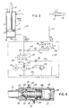
- Fig. 1 illustrates a dockboard 1 that is mounted within a pit or depression 2 in a loading dock 3.
- the dockboard is intended to bridge the gap between the loading dock and the bed of a truck which is located in front of the dock.
- Dockboard 1 includes a supporting frame 4 and the rear end of a ramp or deckplate 5 is pivoted to the frame so that the ramp is movable from a generally horizontal dock level position, where the ramp is generally flush with the upper surface of the dock 3, to an upwardly inclined position, as shown in Fig. 1.
- Hinged to the forward edge of ramp 5 is a lip 6 which can be pivoted from between a downwardly hanging pendant position and an outwardly extended position as shown in Fig. 1, where the lip forms an extension to the ramp.
- the lip is hinged to ramp 5 by a series of lugs 7 which are connected to the underside of the lip and are mounted for rotation on a hinge pin 8 that is connected to the forward end of the ramp.
- the construction of the frame, ramp and lip is conventional and is of a type such as shown in U.S. Patent 4,068,338.
- a main cylinder unit 9 interconnects the frame 4 and the ramp 5 and serves to pivot the ramp from the horizontal dock level position to the upwardly inclined position, while a second lip lifting cylinder unit 10 interconnects the ramp and the lip 6 and serves to pivot the lip to the extended position.
- Main cylinder unit 9 includes a cylinder 11 and a bracket mounted on the lower end of the cylinder is pivotally connected to lugs 13 on frame 4.
- Cylinder 11 is composed of a generally cylindrical outer shell 14, the ends of which are enclosed by an upper head 15 and a lower base 16.
- a piston 17 is mounted for sliding movement in shell 14 and carries a piston rod 18 that extends through upper head 15. The outer end of piston rod 18 is pivotally connected to hinge pin 8.
- Hydraulic fluid is supplied to the upper end of cylinder 11 through a fitting 19.
- piston 17 is provided with a longitudinal passage 20 which is offset laterally from the center axis of the piston.
- Passage 20 includes a small diameter section 21 and a large diameter section 22 which are separated by a valve seat 23.
- a valve ball 24 is mounted within the section 22 and cooperates with the valve seat 23.
- Valve ball 24 is normally maintained in an open condition with respect to valve seat 23 by a pair of springs 25 and 26.
- Spring 25 is interposed between the end of passage section 21 and the valve ball 24, while spring 26 engages the opposite side of the valve ball and is retained within passage section 22 by annular retainer 27 which is threaded within the end of the passage section 22.
- valve 24 hydraulic fluid can flow freely through the passage 20 as the piston moves within the cylinder 11.
- a predetermined downward force is applied to the ramp, as for example, in the event a truck accidentally pulls away from the loading dock when an added load, such as a fork lift truck, is on the ramp
- the flow across the valve ball 24 causes a pressure differential, resulting in the pressure in the lower end of cylinder 11 being greater than the pressure in the upper rod end, thereby closing valve 24 and preventing further descent of the ramp.
- a line 28 connects fitting 19 of cylinder 9 with a shuttle valve 29 that is located in the pump valve body.
- a supply line 30 connects shuttle valve 29 with a pump 33 driven by motor 34 is connected in supply line 30.
- a check valve 35 Also located in supply line 30 between pump 33 and shuttle valve 29 is a check valve 35.
- a return line 32,45 connects shuttle valve 29 with reservoir 31 and an adjustable orifice 36 is connected in return line 32.
- Orifice 36 acts to control the flow of fluid return through line 32 and thus the rate of descent of the ramp as will be hereinafter described.
- a line 37 interconnects the supply line 30, at a location downstream of pump 33, with reservoir 31 and a conventional relief valve 38 is connected in line 37.
- Pilot line 39 interconnects supply line 30 with shuttle valve 29 and a second pilot line 40 interconnects line 28 with the shuttle valve.
- Pressure in line 30 generated by pump 33 will operate through pilot line 39 to move the shuttle valve to the right as shown in Fig. 3, and connects the supply line 30 with the cylinder line 28 to thereby supply fluid to the main cylinder 11.
- the back pressure in line 28 will act through pilot line 40 to move valve 29 to the left as shown in Fig. 3, and thereby connect line 28 to return line 32 to return fluid from the main cylinder to the reservoir 31.
- the hydraulic system also includes a by-pass line 41 which connects cylinder line 28 with a control valve 42, and a fixed orifice 43 is located within line 41.
- a lip cylinder line 44 connects valve 42 to the lip cylinder 10 and a return line 45 connects the valve 42 to the reservoir 31.
- Pilot line 46 interconnects by-pass line 41 and valve 42 so that a predetermined pressure in line 41 will shift valve 42 to the right, as shown in Fig. 3, to connect line 41 with line 44 to supply fluid to the lip cylinder 10.
- a second pilot line 47 acts to maintain valve 42 in the shifted position after the pressure in line 41 has been decreased.
- Valve 42 includes an outer body 48 having a central cavity 49 and a valve 50 is mounted for sliding movement within cavity 49.
- One end of the valve body 48 is provided with a first opening 51 which defines a valve seat and is connected to line 41, while the body 48 is also provided with a second opening 52 which is connected to line 44 and a third opening 53 which is connected to return line 45.
- a pair of collars 54 and 55 are mounted in spaced relation on the valve 50.
- valve 50 is biased to a closed position with respect to the valve seat 51 by a spring 57 which is interposed between collar 55 and a spring retainer 58 which is threaded within the end of the valve body 48.
- Valve 42 is constructed so that a pressure in by-pass line 41, in excess of that required to raise ramp 5 acts on the exposed area of tip 56, resulting in a force of sufficient magnitude to overcome the force of spring 57 and unseat valve tip 56 from seat 51. Once the tip 56 of the valve has been unseated, a larger area of the end of the valve, including the face of collar 54, will be exposed to the fluid pressure so that a substantially lesser pressure will be required to maintain the valve in the opened or shifted position, as compared to the pressure required to initially unseat the tip 56 from the opening 51.
- valve 50 When the valve 50 has been shifted to the right, as shown by the dashed lines in Fig. 4, fluid can then flow from the line 41, through cavity 49 to line 44, to the lip cylinder to thereby extend ram 59 of the lip cylinder to pivot the lip upwardly.
- the surface area of the valve exposed to the fluid pressure is increased so that a lesser pressure is required to exert a force sufficient to overcome the force of spring 57 to retain the valve in the shifted position.
- a lesser force about 1/12 the force required to initially shift the valve, will hold the valve in the shifted position.
- Ramp 5 is normally stored in the horizontal dock level position. After a truck pulls into position in front of the dock 3 for loading, the operator will push the "raise” button on the control panel which operates the motor pump unit to supply pressurized fluid from the reservoir through supply line 30 to the valve 29. The pressurized fluid acting through pilot line 39 will shift valve 29 to thereby connect line 30 with cylinder line 28 to supply pressurized fluid to the main cylinder 9. The pressure on both sides of piston 17 will be balnced due to he free flow through passage 20 in the piston.
- valve 42 shifts to connect line 41 to the lip line 44, the pressure is reduced until the ram 59 of the lip cylinder bottoms out. At this time the relief valve 38 will open to release the pressure in the system.
- the invention provides a substantial simplification of the hydraulic system over conventional types and reduces the overall cost of the hydraulic system. With the system of the invention, only a pair of external hydraulic lines are required, one being connected to the main cylinder 9 and the other to lip cylinder 10. Not only does this system reduce the overall cost, but also provides a cleaner appearance and substantially reduces the number of potential leakage sites.
- the velocity fuse which prevents the rapid descent of the ramp, is built into the piston of the main cylinder unit. This reduces the cost of the velocity fuse over conventional types. As the velocity fuse is located internally of the cylinder, tampering or re-adjustment of the velocity fuse is prevented, as can occur if the velocity fuse is located externally.
- the pressure required to unseat the second or lip control valve to supply fluid to the lip cylinder is adjustable independently of the pressure required to return the lip control valve to its seated position.
- the unseating pressure can be adjusted according to the size and weight of the dockboard without altering the return pressure for the valve, thus providing more precise control of the action of the lip.
- valve 60 is substituted in the hydraulic system, as shown in Fig. 5, for valve 42 of the first embodiment.
- Valve 60 includes a hollow valve body 61 having an externally threaded section 62 that is threaded to pump block 63.
- O-ring assemblies 64 provide seals between valve body 61 and block 63.
- the open inner end of body 61 communicates with pressure passage 65 which is connected to pressure line 41.
- a tubular valve spool 66 is mounted for sliding movement within the central bore 67 of body 61.
- the outer end 68 of spool valve 66 is generally flat and is disposed normal to the axis of the spool valve and contains a small diameter central orifice 69 which provides communication between pressure passage 65 and the internal passage 70 of the spool valve.
- Valve spool 66 is adapted to slide in bore 67, and the central portion of valve spool 66, spaced from end 68, has a reduced diameter to provide an annular clearance between spool 66 and bore 67, as indicated by 71.
- the inner end of body 61 is provided with a plurality of radial ports 72 which communicate with annular chamber 73 in block 63 and chamber 73 is connected through passage 74 and line 44 to lip cylinder 10, as shown in Fig. 5.
- Valve spool 66 is biased to an inner position where the inner end of the valve closes off the ports 72 by a compression spring 75.
- One end of spring 75 bears against an annular shoulder 76 formed in valve spool 66, while the opposite end of spring 75 is engaged with a central recess 77 in valve seat 78, which is mounted in body 61.
- Valve seat 78 is provided with a central opening 79, which is enclosed by a poppet valve 80.
- Valve 80 includes a small diameter end 81, which is received within opening 79, and an the enlarged head 82.
- a coil spring 83 is interposed between head 82 and an adjusting screw 84 which is threaded within a central opening in cap 85.
- Cap 85 is threaded within the outer end of valve body 61.
- a lock nut 86 can be engaged with the outer end of screw 84 to lock the screw in the desired position.
- Valve body 61 is provided with radial ports 87, as well as a radial port 88 which is located axially of ports 87. Ports 87 and 88 communicate with an annular chamber 89 in block 63, and chamber 89 is connected through passage 90 and line 45 to reservoir 31.
- valve spool 66 is provided with a radial port 91 which, as shown in Fig. 6, is closed off by valve body 61 when the spool valve is in the inner closed position, as seen in Fig. 6. However, axial shifting of the valve spool 66 will bring port 91 into communication with port 88 in the valve body.
- a further passage 92 is formed in body 61 and valve seat 78 and provides communication between the interior of cap 85 and chamber 89 in block 63.
- poppet valve 80 When poppet valve 80 is opened, fluid can flow from the interior of the valve spool 66 through opening 79 and then through passage 92 and chamber 89 to reservoir 31.
- the ramp is elevated in the manner described in connection with the first embodiment.
- the pressure in line 28 will increase and the increased pressure acting through line 41 will be applied to the valve spool 66 through passage 65. Due to orifice 69 and passage 70, the pressure will be applied to both ends of the spool valve.
- the force of the fluid pressure acting on the exposed area of the lower end of spool valve 66 is equal to the force acting on the upper end of the spool valve (the sum of the force of spring 75 plus the force of the fluid pressure acting on the exposed area of the upper end), the valve will be maintained in the closed position, as shown in Fig. 6.
- the fluid pressure acting through spool valve 66 will also be applied to the inner small diameter end 81 of poppet valve 80, which is biased to a closed position by spring 83.
- the poppet valve will open, allowing fluid to flow through passage 92, chamber 89, passage 90, and line 45 to the reservoir 31
- As fluid flows through the spool valve it passes through the small diameter orifice 69, causing a pressure drop across the orifice, which is sufficient to produce a higher force on end 68 of the valve, as opposed to the opposite end.
- Valve spool 66 When the extended lip engages the truck bed, the descent of the ramp and lip is terminated with the result that the pressure in lines 28 and 41 will be reduced to ambient. Valve spool 66 will then shift to its original position, as seen in Fig. 6. When the truck pulls away from the dock, the lip is then free to fall by gravity to its original pendant position, and as the lip falls, fluid will be returned from the lip cylinder 10 through line 44 and will flow through passage 74, chamber 73, ports 72 and clearance 71 to ports 87, chamber 89, passage 90 to reservoir 31.
- Figs. 5 and 6 The construction shown in Figs. 5 and 6 has distinct advantages. While the lips of different dockboards may be somewhat uniform in size and weight, the ramps of dockboards may vary considerably in size and weight.
- the sequence pressure which is the pressure in excess of that required to raise the ramp and supply pressure to the lip cylinder, will necessarily vary depending upon the weight of the ramp.
- sequence pressure and the return pressure which is the pressure at which the lip control valve will return to its original position
- an increase in sequence pressure in a conventional system, will necessarily result in an increase in return pressure.
- Increasing the return pressure will mean that the lip will fall by gravity at a higher pressure, which is undesirable, for it is preferred that the return pressure be as low as possible.
Landscapes
- Engineering & Computer Science (AREA)
- Mechanical Engineering (AREA)
- Fluid-Pressure Circuits (AREA)
- Auxiliary Methods And Devices For Loading And Unloading (AREA)
- Body Structure For Vehicles (AREA)
Claims (5)
- Hydraulisch betriebenes Andockbrett mit einer Haltekonstruktion (4), einer Rampe (5), die mit ihrer Hinterkante an die Haltekonstruktion angelenkt und zwischen einer im allgemeinen horizontalen Stellung und einer nach oben geneigten Stellung verschwenkbar ist, mit einer Klappe (6), die an der Vorderkante der Rampe angelenkt und zwischen einer nach unten hängenden Stellung und einer sich nach oben erstrekkenden Stellung bewegbar ist, mit einer ersten Hydraulikzylindereinheit (9), die die Rampe (5) und die Haltekonstruktion (4) verbindet, mit einer zweiten Hydraulikzylindereinheit (10), die die Rampe (5) und die Klappe (6) verbindet, mit einem Hydrauliksystem zum Zuführen von Hydraulikfluid zu den ersten und zweiten Zylindereinheiten und einem Reservoir (31) für Hydraulikfluid, mit ersten Leitungsmitteln (30, 28), die das Reservoir und die erste Zylindereinheit (9) verbinden, mit Pumpmitteln (33) für das Zuführen von Hydraulikfluid unter Druck durch das erste Leitungsmittel (30, 28) zu der ersten Zylindereinheit (9), um dadurch die erste Zylindereinheit zu betätigen und die Rampe (5) anzuheben, mit einem zweiten Leitungsmittel (41), das an das erste Leitungsmittel (30, 28) angeschlossen ist, mit einem dritten Leitungsmittel (44), das an die zweite Zylindereinheit (10) angeschlossen ist, mit Ventilmitteln (42, 60), die das zweite Leitungsmittel (41) und das dritte Leitungsmittel (44) verbinden, mit vierten Leitungsmitteln (45), die das Ventilmittel mit dem Reservoir (31) verbinden, wobei die Ventilmittel (42, 60) eine erste Stellung haben, in der das zweite Leitungsmittel (41) an das dritte Leitungsmittel (44) angeschlossen ist und eine zweite Stellung, in der das dritte Leitungsmittel (44) mit dem vierten Leitungsmittel (45) verbunden ist, wobei die Ventilmittel (42, 60) so gestaltet sind, daß ein erster erhöhter Fluiddruck in dem zweiten Leitungsmittel (41), der über dem Druck liegt, der erforderlich ist, um die Rampe (5) anzuheben, die Ventilmittel (42, 60) von der zweiten Stellung in die erste Stellung bewegen und dadurch Druckfluid zu der zweiten Zylindereinheit (10) leitet, um die Klappe (6) auszufahren, und wobei die Ventilmittel (42, 60) ferner so gestaltet sind, daß bei einem Abnehmen von Fluiddruck von dem ersten Druck auf einen zweiten Fluiddruck, der wesentlich unter dem ersten Druck liegt, die Ventilmittel von der ersten Stellung in die zweite Stellung bewegt werden, um dadurch Fluid von der zweiten Zylindereinheit (10) durch die Ventilmittel 42, 60) in das Reservoir (31) zurückzuführen, dadurch gekennzeichnet, daß die Ventilmittel (42, 60) Einstellmittel (84) aufweisen, um die Größe eines der Drücke nachzustellen, die erforderlich sind, um die Ventilmittel (42, 60) unabhängig von dem jeweils anderen Druck zu verstellen.
- Andockplatte nach Anspruch 1, wobei das Einstellmittel so gestaltet ist, daß die Größe des ersten Drucks unabhängig von der Größe des zweiten Drucks eingestellt werden kann.
- Andockplatte nach Anspruch 2, wobei das Ventilmittel (60) eine Ventilhülse (66) aufweist, die eine Längsbohrung mit einer Öffnung (69) von kleinem Durchmesser in einem ersten Ende aufweist, erste Vorspannmittel (75), die gegen das zweite Ende der Ventilhülse (66) wirken, um die Ventilhülse (66) in die zweite Stellung zu drücken, ein zweites Ventilelement (80), das die Längsbohrung und das Reservoir verbindet und zwischen einer offenen Stellung und einer geschlossenen Stellung bewegbar ist, mit zweiten Vorspannmitteln (83) zum Vorspannen des zweiten Ventilelements (80) in die geschlossene Stellung, wobei der Fluidstrom in dem ersten Leitungsmittel durch das zweite Leitungsmittel (41) und die Längsbohrung wirkt, wenn die Ventilhülse (66) in der zweiten Stellung steht, um das zweite Ventilelement (80) zu öffnen und um eine Druckdifferenz an gegenüberliegenden Enden der Ventilhülse (66) hervorzurufen, um dadurch die Ventilhülse (66) in die erste Stellung zu bewegen und Fluid von dem ersten Leitungsmittel (28) durch das dritte Leitungsmittel (44) der zweiten Zylindereinheit (10) zuzuführen, wobei das Einstellmittel (84) funktionsmäßig an das zweite Vorspannmittel (83) angeschlossen ist.
- Andockplatte nach Anspruch 3, wobei das zweite Vorspannmittel (83) eine Feder aufweist und wobei die von dem zweiten Vorspannmittel (83) ausgeübte Kraft größer als die Kraft ist, die von dem ersten Vorspannmittel (75) ausgeübt wird.
- Andockplatte nach Anspruch 1, wobei die zweite Zylindereinheit (9) einen Zylinder (14) und einen Kolben (17) aufweist, der in dem Zylinder (14) verschiebbar montiert ist, wobei die erste Zylindereinheit (9) außerdem eine Kolbenstange (18) aufweist, die an den Kolben (17) angeschlossen ist und sich nach außen durch ein oberes Ende des Zylinders (14) erstreckt, das erste Leitungsmittel (28) an das obere Ende des Zylinders (14) angeschlossen ist, der Kolben (17) eine Längsbohrung (20, 21) aufweist, ein Ventil (20-27) mit einem Ventilkörper (24) in der Bohrung (20, 21) angeordnet ist und eine offene und eine geschlossene Stellung besitzt, das Ventil (20-27) in dem Kolben (17) ferner Mittel (25) zum Vorspannen des Ventilkörpers (24) in die offene Stellung aufweist, und Mittel (26) besitzt, die auf eine vorgegebene, abwärts gerichtete Kraft ansprechen, die auf die Rampe (5) wirkt, um die Kraft des Vorspannmittels (25) zum Schließen des Vetilkörpers (24) zu überwinden und ein Absinken der Rampe (5) zu verhindern.
Applications Claiming Priority (2)
| Application Number | Priority Date | Filing Date | Title |
|---|---|---|---|
| US07/466,054 US4955923A (en) | 1988-11-25 | 1990-01-16 | Hydraulically operated dockboard |
| US466054 | 1990-01-16 |
Publications (2)
| Publication Number | Publication Date |
|---|---|
| EP0440349A1 EP0440349A1 (de) | 1991-08-07 |
| EP0440349B1 true EP0440349B1 (de) | 1994-12-28 |
Family
ID=23850266
Family Applications (1)
| Application Number | Title | Priority Date | Filing Date |
|---|---|---|---|
| EP91300280A Expired - Lifetime EP0440349B1 (de) | 1990-01-16 | 1991-01-15 | Hydraulisch betätigte Laderampe |
Country Status (5)
| Country | Link |
|---|---|
| US (1) | US4955923A (de) |
| EP (1) | EP0440349B1 (de) |
| JP (1) | JPH07106878B2 (de) |
| CA (1) | CA2034195C (de) |
| DE (1) | DE69106152T2 (de) |
Cited By (1)
| Publication number | Priority date | Publication date | Assignee | Title |
|---|---|---|---|---|
| DE102011054338A1 (de) | 2011-10-10 | 2013-04-11 | QualiXperts GmbH | Vorrichtung zur Überführung von Lasten |
Families Citing this family (26)
| Publication number | Priority date | Publication date | Assignee | Title |
|---|---|---|---|---|
| NL8900557A (nl) | 1989-03-07 | 1990-10-01 | Rolflex Oost Nederland | Beweegbare laadbrug. |
| US5416941A (en) * | 1991-07-01 | 1995-05-23 | Kelley Company Inc. | Dockboard having an improved return-to-dock-level mechanism |
| US5205010A (en) * | 1991-08-13 | 1993-04-27 | Kelley Company Inc. | Return-to-dock level mechanism for a hydraulic dockboard |
| US5274867A (en) * | 1991-12-26 | 1994-01-04 | Kelley Company Inc. | Hydraulically operated edge-of-dock leveler |
| KR100208845B1 (ko) * | 1991-12-26 | 1999-07-15 | 로버트 제이. 워너 | 팽창가능한 백을 사용한 도크 레벨링 장치 |
| US5446938A (en) * | 1993-10-04 | 1995-09-05 | Kelley Company Inc. | Bag construction for a dockleveler |
| US5600859A (en) * | 1995-01-31 | 1997-02-11 | Kelley Company, Inc. | Dock leveler in which the ramp is raised and lowered using an inflatable member and method of use |
| US6460212B2 (en) | 1993-10-04 | 2002-10-08 | Kelley Company, Inc. | Dock leveler having an inflatable member |
| US5996156A (en) * | 1995-01-31 | 1999-12-07 | Kelley Company, Inc. | Dock leveler raised by deflating an inflatable member |
| US5481774A (en) * | 1993-10-04 | 1996-01-09 | Kelley Company, Inc. | Support mechanism for a dockleveler lift bag |
| US5802650A (en) * | 1993-10-04 | 1998-09-08 | Kelley Company, Inc. | Dock leveler having an inflatable member |
| US5471693A (en) * | 1993-10-04 | 1995-12-05 | Kelley Company Inc. | Support and attachment mechanism for a dockleveler lift bag |
| US6711774B2 (en) | 1993-10-04 | 2004-03-30 | Kelley Company, Inc. | Dock leveler having an inflatable member |
| US5511267A (en) * | 1994-08-02 | 1996-04-30 | The Serco Corporation | Dock leveler hydraulic circuit |
| US5544381A (en) * | 1994-08-02 | 1996-08-13 | United Dominion Industries, Inc. | Dock leveler hydraulic circuit |
| US5522107A (en) * | 1995-01-31 | 1996-06-04 | Kelley Company, Inc. | Retaining arrangement for an inflatable member in a dock leveler |
| US5475888A (en) * | 1995-01-31 | 1995-12-19 | Kelley Company, Inc. | Lip lifting mechanism for a dock leveler |
| US5522108A (en) * | 1995-01-31 | 1996-06-04 | Kelley Company, Inc. | Dock leveler having a ramp movable to a raised position by inflation of an inflatable member, with a filler for occupying volume within the inflatable member |
| FR2731418B1 (fr) * | 1995-03-10 | 1997-04-18 | Hymeca Manutention | Procede et dispositif de detection et de controle de la perte d'appui de la levre d'un niveleur de quai |
| US6065172A (en) * | 1998-06-09 | 2000-05-23 | Rite-Hite Holding Corporation | Hydraulic control circuit |
| US6643880B1 (en) | 1999-11-01 | 2003-11-11 | Kelley Company, Inc. | Dock leveler |
| US6327733B1 (en) * | 1999-12-10 | 2001-12-11 | United Dominion Ind, Inc. | Mechanically actuated dock leveler with hydraulic assist |
| CA2335897C (fr) * | 2001-02-13 | 2006-01-24 | Delaney Machinerie Inc. | Systeme pour soulever et deplacer une charge |
| US20040221404A1 (en) * | 2003-04-28 | 2004-11-11 | Brian Bender | Double-wall inflatable column assembly for a dock leveler |
| US7503089B2 (en) * | 2005-04-05 | 2009-03-17 | Rite-Hite Holding Corporation | Inflatable actuator for a dock leveler deck |
| DE102010011325A1 (de) | 2010-03-13 | 2011-09-15 | Novoferm Gmbh | Verfahren zum Betrieb einer Überladebrücke |
Family Cites Families (17)
| Publication number | Priority date | Publication date | Assignee | Title |
|---|---|---|---|---|
| CA717691A (en) * | 1965-09-14 | P. Dieter Donald | Dockboard | |
| US3175238A (en) * | 1962-03-30 | 1965-03-30 | James H Elkus | Adjustable loading ramp |
| US3170179A (en) * | 1962-04-24 | 1965-02-23 | Richard C Layne | Dockboard unit |
| US3290710A (en) * | 1964-11-17 | 1966-12-13 | Symington Wayne Corp | Lip-operated switching device for power operated loading platform |
| US3290709A (en) * | 1964-11-17 | 1966-12-13 | Symington Wayne Corp | Automatic lip for power operated loading platform |
| US3345665A (en) * | 1965-09-29 | 1967-10-10 | Symington Wayne Corp | Fluid-operated ramp having automatic lip |
| US3388413A (en) * | 1966-04-11 | 1968-06-18 | Autoquip Corp | Hydraulic dock ramp controls |
| US3656199A (en) * | 1970-11-02 | 1972-04-18 | Kelley Co Inc | Safety mechanism for a hydraulically operated dockboard |
| JPS5715913U (de) * | 1980-06-30 | 1982-01-27 | ||
| US4365374A (en) * | 1980-08-04 | 1982-12-28 | Kelley Company Inc. | Hydraulically operated dockboard |
| JPS57186601A (en) * | 1981-05-14 | 1982-11-17 | Toshiba Corp | Hydraulic sudden change preventing device of hydraulic driving system |
| JPS58172197A (ja) * | 1982-04-02 | 1983-10-08 | 東急車輌製造株式会社 | 多重ストロ−クホイスト装置 |
| DE3303207C2 (de) * | 1983-02-01 | 1985-08-01 | Kurt 3015 Wennigsen Alten | Überfahrbrücke für Rampen |
| US4641388A (en) * | 1984-08-01 | 1987-02-10 | Kelley Company, Inc. | Hydraulic control system for a dockboard |
| EP0251499A1 (de) * | 1986-07-01 | 1988-01-07 | Smiths Industries Public Limited Company | Laderampen |
| DE3708446C1 (de) * | 1987-03-16 | 1988-06-16 | Alten K | UEberladebruecke fuer Rampen |
| US4827549A (en) * | 1987-12-30 | 1989-05-09 | Dock Leveler Manufacturing, Inc. | Hydraulic dock leveler |
-
1990
- 1990-01-16 US US07/466,054 patent/US4955923A/en not_active Expired - Lifetime
-
1991
- 1991-01-15 DE DE69106152T patent/DE69106152T2/de not_active Expired - Fee Related
- 1991-01-15 CA CA002034195A patent/CA2034195C/en not_active Expired - Fee Related
- 1991-01-15 EP EP91300280A patent/EP0440349B1/de not_active Expired - Lifetime
- 1991-01-16 JP JP3003506A patent/JPH07106878B2/ja not_active Expired - Lifetime
Cited By (1)
| Publication number | Priority date | Publication date | Assignee | Title |
|---|---|---|---|---|
| DE102011054338A1 (de) | 2011-10-10 | 2013-04-11 | QualiXperts GmbH | Vorrichtung zur Überführung von Lasten |
Also Published As
| Publication number | Publication date |
|---|---|
| CA2034195C (en) | 1999-07-13 |
| DE69106152T2 (de) | 1995-08-10 |
| JPH04213522A (ja) | 1992-08-04 |
| DE69106152D1 (de) | 1995-02-09 |
| US4955923A (en) | 1990-09-11 |
| JPH07106878B2 (ja) | 1995-11-15 |
| EP0440349A1 (de) | 1991-08-07 |
| CA2034195A1 (en) | 1991-07-17 |
Similar Documents
| Publication | Publication Date | Title |
|---|---|---|
| US4955923A (en) | Hydraulically operated dockboard | |
| US4365374A (en) | Hydraulically operated dockboard | |
| US4597584A (en) | Automatic levelling system | |
| US3990668A (en) | Hydraulic suspension seat assembly | |
| US4976317A (en) | Well tool hydrostatic release means | |
| US5797310A (en) | Dual self level valve | |
| US4500071A (en) | Dual hydraulic lifts | |
| US4641388A (en) | Hydraulic control system for a dockboard | |
| US4088151A (en) | Cylinder locking apparatus | |
| CA1178167A (en) | Tiltcab truck with hydraulic lost motion | |
| EP1218241A1 (de) | Hydraulisches system für flugzeugfahrwerk | |
| AU739640B2 (en) | Valves | |
| JPH08511487A (ja) | 高さ調節弁とそのためのダンプ弁 | |
| US5274867A (en) | Hydraulically operated edge-of-dock leveler | |
| US4165675A (en) | Load check valve cylinder mounted | |
| US2974490A (en) | Bumper jack and fluid system | |
| GB2108242A (en) | A hydraulic system of a fork lift truck | |
| EP0004165B1 (de) | Arbeitszylinder | |
| US5188015A (en) | Automatically sequenced hydraulic cylinder mechanism | |
| US5073067A (en) | Mine roof support | |
| US5454669A (en) | Yield valve | |
| US4146998A (en) | Position responsive valve for controlling the retraction rate of a lower boom in an articulated boom assembly | |
| GB2104961A (en) | Motor vehicle tilting cab actuator | |
| SU1763260A1 (ru) | Транспортное средство | |
| GB2192854A (en) | Hydraulic dock leveller |
Legal Events
| Date | Code | Title | Description |
|---|---|---|---|
| PUAI | Public reference made under article 153(3) epc to a published international application that has entered the european phase |
Free format text: ORIGINAL CODE: 0009012 |
|
| AK | Designated contracting states |
Kind code of ref document: A1 Designated state(s): DE FR GB NL |
|
| 17P | Request for examination filed |
Effective date: 19920120 |
|
| 17Q | First examination report despatched |
Effective date: 19930419 |
|
| GRAA | (expected) grant |
Free format text: ORIGINAL CODE: 0009210 |
|
| AK | Designated contracting states |
Kind code of ref document: B1 Designated state(s): DE FR GB NL |
|
| REF | Corresponds to: |
Ref document number: 69106152 Country of ref document: DE Date of ref document: 19950209 |
|
| ET | Fr: translation filed | ||
| PLBE | No opposition filed within time limit |
Free format text: ORIGINAL CODE: 0009261 |
|
| STAA | Information on the status of an ep patent application or granted ep patent |
Free format text: STATUS: NO OPPOSITION FILED WITHIN TIME LIMIT |
|
| 26N | No opposition filed | ||
| REG | Reference to a national code |
Ref country code: GB Ref legal event code: IF02 |
|
| PGFP | Annual fee paid to national office [announced via postgrant information from national office to epo] |
Ref country code: FR Payment date: 20020211 Year of fee payment: 12 |
|
| PGFP | Annual fee paid to national office [announced via postgrant information from national office to epo] |
Ref country code: GB Payment date: 20020220 Year of fee payment: 12 |
|
| PGFP | Annual fee paid to national office [announced via postgrant information from national office to epo] |
Ref country code: DE Payment date: 20020221 Year of fee payment: 12 |
|
| PGFP | Annual fee paid to national office [announced via postgrant information from national office to epo] |
Ref country code: NL Payment date: 20020225 Year of fee payment: 12 |
|
| PG25 | Lapsed in a contracting state [announced via postgrant information from national office to epo] |
Ref country code: GB Free format text: LAPSE BECAUSE OF NON-PAYMENT OF DUE FEES Effective date: 20030115 |
|
| PG25 | Lapsed in a contracting state [announced via postgrant information from national office to epo] |
Ref country code: NL Free format text: LAPSE BECAUSE OF NON-PAYMENT OF DUE FEES Effective date: 20030801 Ref country code: DE Free format text: LAPSE BECAUSE OF NON-PAYMENT OF DUE FEES Effective date: 20030801 |
|
| GBPC | Gb: european patent ceased through non-payment of renewal fee | ||
| PG25 | Lapsed in a contracting state [announced via postgrant information from national office to epo] |
Ref country code: FR Free format text: LAPSE BECAUSE OF NON-PAYMENT OF DUE FEES Effective date: 20030930 |
|
| NLV4 | Nl: lapsed or anulled due to non-payment of the annual fee |
Effective date: 20030801 |
|
| REG | Reference to a national code |
Ref country code: FR Ref legal event code: ST |