EP0441131B1 - Procédé et appareil pour alimenter avec un ruban une machine de production, en particulier une machine de conditionnement - Google Patents
Procédé et appareil pour alimenter avec un ruban une machine de production, en particulier une machine de conditionnement Download PDFInfo
- Publication number
- EP0441131B1 EP0441131B1 EP91100381A EP91100381A EP0441131B1 EP 0441131 B1 EP0441131 B1 EP 0441131B1 EP 91100381 A EP91100381 A EP 91100381A EP 91100381 A EP91100381 A EP 91100381A EP 0441131 B1 EP0441131 B1 EP 0441131B1
- Authority
- EP
- European Patent Office
- Prior art keywords
- reservoir
- web
- filling
- layers
- drive
- Prior art date
- Legal status (The legal status is an assumption and is not a legal conclusion. Google has not performed a legal analysis and makes no representation as to the accuracy of the status listed.)
- Expired - Lifetime
Links
- 238000000034 method Methods 0.000 title claims description 14
- 238000004806 packaging method and process Methods 0.000 title claims description 13
- 239000000463 material Substances 0.000 claims description 100
- 238000012545 processing Methods 0.000 claims description 11
- 239000005022 packaging material Substances 0.000 claims description 4
- 230000001154 acute effect Effects 0.000 claims description 2
- 230000009193 crawling Effects 0.000 claims description 2
- 238000007599 discharging Methods 0.000 claims 1
- 230000003287 optical effect Effects 0.000 claims 1
- 238000003860 storage Methods 0.000 description 31
- 238000010586 diagram Methods 0.000 description 5
- 230000001133 acceleration Effects 0.000 description 4
- 238000005303 weighing Methods 0.000 description 4
- 239000004744 fabric Substances 0.000 description 3
- 238000012432 intermediate storage Methods 0.000 description 2
- 238000012360 testing method Methods 0.000 description 2
- 230000015572 biosynthetic process Effects 0.000 description 1
- 239000000109 continuous material Substances 0.000 description 1
- 230000003111 delayed effect Effects 0.000 description 1
- 238000011161 development Methods 0.000 description 1
- 230000018109 developmental process Effects 0.000 description 1
- 230000006870 function Effects 0.000 description 1
- 238000005259 measurement Methods 0.000 description 1
- 238000012858 packaging process Methods 0.000 description 1
- 238000010008 shearing Methods 0.000 description 1
- 210000002105 tongue Anatomy 0.000 description 1
- 238000012549 training Methods 0.000 description 1
Images


Classifications
-
- B—PERFORMING OPERATIONS; TRANSPORTING
- B65—CONVEYING; PACKING; STORING; HANDLING THIN OR FILAMENTARY MATERIAL
- B65H—HANDLING THIN OR FILAMENTARY MATERIAL, e.g. SHEETS, WEBS, CABLES
- B65H20/00—Advancing webs
- B65H20/30—Arrangements for accumulating surplus web
- B65H20/32—Arrangements for accumulating surplus web by making loops
-
- B—PERFORMING OPERATIONS; TRANSPORTING
- B31—MAKING ARTICLES OF PAPER, CARDBOARD OR MATERIAL WORKED IN A MANNER ANALOGOUS TO PAPER; WORKING PAPER, CARDBOARD OR MATERIAL WORKED IN A MANNER ANALOGOUS TO PAPER
- B31B—MAKING CONTAINERS OF PAPER, CARDBOARD OR MATERIAL WORKED IN A MANNER ANALOGOUS TO PAPER
- B31B70/00—Making flexible containers, e.g. envelopes or bags
- B31B70/02—Feeding or positioning sheets, blanks or webs
- B31B70/10—Feeding or positioning webs
-
- B—PERFORMING OPERATIONS; TRANSPORTING
- B65—CONVEYING; PACKING; STORING; HANDLING THIN OR FILAMENTARY MATERIAL
- B65H—HANDLING THIN OR FILAMENTARY MATERIAL, e.g. SHEETS, WEBS, CABLES
- B65H2408/00—Specific machines
- B65H2408/20—Specific machines for handling web(s)
- B65H2408/21—Accumulators
- B65H2408/212—Accumulators of zigzag-type
Definitions
- the invention relates to a device for feeding a material web, preferably of packaging material to form separable blanks, to a processing or processing machine, in particular a packaging machine or folding assembly thereof, with a drive for the material web and with a material store through which the material web can be conveyed is, wherein means for detecting the memory content are provided, by means of which the drive of the material web can be controlled, in such a way that a minimum memory content is not undershot and a maximum memory content is not exceeded.
- the processing machine in particular the packaging machine, is usually operated in different operating states, which often and frequently alternate quickly.
- the machine's operating states include, for example, standstill, normal running, brief overspeed operation or brief crawling.
- the heavy bobbin has a mass inertia, which makes an immediate, albeit delayed, reaction to the needs of the machine or the operating conditions of the machine hardly or not possible.
- heavy bobbins are used in connection with packaging machines if, for example, packaging material made of thin cardboard is to be processed into packaging.
- packaging processes it is known to already subdivide the material web into packaging blanks, the individual blanks remaining connected to one another via residual connections and thus being able to continue to be provided as a material web on a bobbin. Only in the area of the packaging machine are the individual cuts cut from the material web, for example by tearing or shearing off.
- DE-OS 37 16 897, DE-OS 37 35 674 and DE-OS 37 35 675 is made in connection with this prior art reference is made to DE-OS 37 16 897, DE-OS 37 35 674 and DE-OS 37 35 675.
- a device for handling a web of fabric is known from US-A-4,589,580.
- the fabric web is fed into a vertical store by suitable drive rollers.
- the web should come to lie in a zigzag fold in the memory.
- the fabric web in the store will form an unordered heap, to which additional tissue is fed from above and from which tissue is removed downwards.
- a bobbin or a drive for this are not recognizable.
- the object of the present invention is to provide a method and a device for particularly advantageous coordination between the memory content and the drive of the material web.
- control of the drive of the bobbin according to the invention advantageously and in a surprisingly simple manner enables the bobbin to fill the material store, practically irrespective of the operating states of the subsequent machine, can be driven in a continuously rotating manner, under circumstances with moderately changing speeds, but largely without interruptions. In particular, complicated stopping or restarting of the bobbin can be largely avoided in this way.
- the removal of material from the material store is preferably only released if there is at least one predetermined intermediate storage content, between the minimum and the maximum storage content, or at least until the intermediate storage content has been reached, the introduction takes place faster than the removal.
- the bobbin is thus preferably driven at a speed which, depending on its size, depends on the degree of filling of the material store.
- the drive of the bobbin is maintained as long as possible, that is to say it is carried out continuously, albeit at a variable speed.
- the bobbin is preferably only stopped when the material store is completely filled and there is no discharge from the material store. Certain emergency stop situations can of course also be provided, for example if the material web breaks.
- a device is characterized in that the material store comprises a storage container which is intended and set up for receiving the material web in zigzag-shaped layers, that the means for detecting the memory content comprise measuring elements which are used to determine the number of layers in the Material storage are formed and by which the memory content can be measured in this way, and that a motor for driving a bobbin of the material web can be controlled as a function of the determined memory content.
- inventive method can in particular be carried out by means of such a device according to the invention.
- Preferred training and further developments can be found in claims 7 to 12.
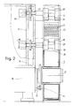
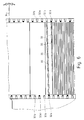
- FIG. 1 shows a section from a feed device according to the invention for feeding a material web, in particular a packaging material web, to a packaging machine (not shown) in a side view.
- the material web 10 is drawn off from a bobbin 11 which is driven in rotation via a drive pin 12.
- the drive pin has a gear 13 which meshes with a pinion 14 of a shaft 15 of a motor drive 16 (FIG. 2).
- the motor drive 16 is arranged on a machine frame 17.
- the material web 10 is pulled off the rotating bobbin 11 by means of a pair of rollers 18, 19 and inserted into a storage housing 20 for a material store of the material web 10.
- the driven roller 18 acts as a push roller.
- the roller 19 can be designed as a rotating pressure roller.
- the material web 10 is inserted in zigzag layers 21 by the pair of rollers 18, 19 into the storage housing 20.
- the storage housing 20 is oriented perpendicularly, so that a layer stack with a recognizable upper edge forms due to the weight of the layers 21.
- a pair of traction rollers 22, 23 are provided for conveying the material web 10 out of the storage housing 20.
- the roller 22 is a driven pull roller
- the roller 23 is a rotating pressure roller.
- the material web 10 is conveyed further to the packaging machine (not shown) via further conveyor elements, in particular conveyor rollers 24.
- the two driven rollers 18 and 22 have rotary pulse generators, via which the rotational movement of these rollers is registered.
- Rotary pulse generators are preferably used which emit 1000 pulses per revolution of the roller.
- the memory content of the memory housing 22 can be determined by comparing the rotational movements of the two rollers 18 and 22 determined in this way. For additional, more direct determination of the memory content, sensors or measuring elements are provided, which are explained in more detail in particular in connection with FIGS. 4 to 6.
- the material web 10 is indicated in FIG. 1 once with a solid line when the bobbin is approximately full and once with a dash-dotted line when the bobbin is approximately empty (reference number 10 ').
- the storage housing 20 is largely box-shaped, the lower and the upper end face being open in the exemplary embodiment according to FIG. 1 for conveying the material web 10 through.
- the storage housing 20 each has a pair of outlet parts 25. These outlet parts 25 protrude in the direction of the rollers 18, 19 or 22, 23 and ensure safe and exact feeding or removal of the material web.
- outlet parts 25 are shaped like tongues.
- the rollers 18, 19 and 22, 23 have recesses 26 into which the outlet parts 25 protrude approximately tangentially.
- the storage housing 20 has a continuous slot 27 which extends in the conveying direction of the material web 10 and through which the layers 21 of the material web 10 in the storage housing 20 can be observed.
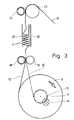
- FIG. 3 once again shows the exemplary embodiment according to FIG. 1 in a more schematic representation.
- the topology of the material web feed is made clearer.
- the storage housing 20 is again largely perpendicular.
- a measuring element 30, which comprises a series of sensors arranged one above the other.
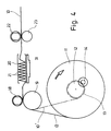
- FIG. 4 shows a second exemplary embodiment of a feed device according to the invention in a schematic representation, which corresponds to the representation of FIG. 3.
- the embodiment according to FIG. 4 differs from the embodiment according to FIG. 3 essentially in that the storage housing 20 is arranged horizontally.
- the layers 21 of the material web 10 in the storage housing 20 do not form a stack of layers with a recognizable upper edge in this orientation of the storage housing 20.
- a measuring element 31 is therefore assigned to the storage housing 20 and comprises a weighing element or a weighing device. In this embodiment of the device, the memory content is thus recorded in a weighing manner.
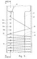
- FIG. 5 and 6 show a region of the memory housing 20 according to the embodiment of FIG. 1.
- a plurality of sensors 32a and 32b are arranged in the interior of the storage housing 20.
- the sensors 32a, b are arranged one above the other, at a distance from one another, which corresponds approximately to the distance between two layers 21 in the layer stack forming in the storage housing 20.
- a transmitter 32a and a receiver 32b are arranged opposite one another as sensors.
- the sensors 32a, b which are assigned to one another are arranged somewhat offset in height from one another, so that a test beam 33 emitted by the transmitter 32a extends at a somewhat acute angle (angle 34) to the respectively adjacent folded edge 35 of the layers 21 of the material web 10. This ensures that each test beam 33 intersects a folded edge 35 in the maximum case, which is thus detected by the receiver 32b. It is thus possible to use sensors 32a and b to determine the number of layers 21 of the material web 10 in the storage housing 20, at least the layers 21, which together form a stack of layers due to the weight of the material web 10.
- the zigzag-shaped folding and layering of the material web 10 shown can in particular be carried out in a simple manner in the case of material webs which are already divided into individual blanks, but which are still connected to one another via residual connections, since in the region of these residual connections the material web 10 is weakened in such a way that a fold edge 35 can easily be formed in this area, so that each layer 21 is formed by a blank.
- FIG. 7 and 8 show block diagrams for a control of the feed device according to the invention, via which the drive 16 of the bobbin 11 is controlled.
- the controls each include measuring elements 30 and 31, respectively.
- the control according to FIG. 7 is operated largely analog, while the control according to FIG. 8 is operated largely digitally.
- the first circuit has been assigned to a sensor measuring element 30 and the second circuit has been assigned to a weighing measuring element 31. It could also be a reverse Assignment done.
- circuits shown as signal transmitters comprise rotary pulse transmitters 36 and 37 which are assigned to the rollers 18 and 22.
- the output signal of the measuring element 30 or 31 is fed to an analog / digital converter 38.
- the signals of the rotary pulse generators 36 and 37 and the output signal of the analog / digital converter (ADC) are supplied to counters 39..41. In the embodiment shown in FIG. 7, these signals are continued without a counter.
- the rotary pulse generator 37 of the pull roller 22 and the measuring member 30 and 31 are connected to the inputs of a summer 42.
- the output signal of the summer 42 and the output signal of the rotary pulse generator 36 of the push roller 18 are given to the inputs of a comparator 43.
- the output signal of the comparator 43 is fed to a speed controller 44, which controls the motor drive 16 of the bobbin 11.
- a motor (emergency) shutdown 45 is assigned to the motor drive 16 via the speed controller 44.
- the output signal of the measuring element 30 or 31 is also fed to a speed controller 46 with which the drive element 29 of the pull roller 22 is controlled.
- the speed controller 46 is preceded by a release member 47.
- the mark 48 means a minimum fill level
- the mark 49 an intermediate fill level
- the mark 50 a maximum fill level
- the mark 51 a complete filling of the memory housing 20.
- the feed device according to the invention or its control works as follows:
- the speed of the drive in particular a relatively heavy bobbin, is to be adapted to the partially intermittent material take-off to a packaging machine, with as little speed change or acceleration as possible.
- the pressure roller 19 is pressed against the push roller 18 and the pressure roller 23 against the pull roller 22.
- the rotary pulse generators 36 and 37 the push roller 18 and the pull roller 22 emit angular momentum during the movement of the rollers 18, 22, preferably 1000 impulses per revolution, whereby the rotational movement of the rollers 18, 22 is detected quantitatively. From this rotary movement, it is determined how much material is input into the storage housing 20 and how much material, in contrast, is removed from the storage housing 20. The memory content of the memory housing 20 is determined from this.
- the memory content of the memory housing 20 is also determined by the measuring element 30 or 31. Both measurements are linked to one another via the summer 42.
- the bobbin 11 and the pusher roller 18 are first driven alone, with the storage housing 20 empty, without the pull roller 22 until the intermediate mark 49 is reached.
- the memory has thus reached a filling level at which when the material removal is started with relatively high acceleration the bobbin can adapt to the removal speed with relatively low acceleration without the Memory becomes empty.
- the drive member 29 for the pull roller 22 is started and thus the removal or removal from the storage housing 20 is released. Thereafter, the drive 16 of the bobbin 11 is operated depending on the fill level of the storage housing 20, specifically within the limits of the marks 48 and 50 for the minimum and maximum fill level. If the intermediate mark 49 is undershot, the speed of the bobbin 11 is increased by the amount that the mark falls below this mark until this mark 49 is reached or exceeded again. If the mark 49 is exceeded, the bobbin is slowed down by a corresponding amount. This ensures that the degree of filling is largely kept in the region of the intermediate mark 49.
- variable speed component of the bobbin 11 is preferably added to a basic speed of the bobbin.
- the drive 29 of the pull roller 22 for the conveyance is switched off. If, on the other hand, the maximum mark 50 is reached and exceeded, the drive 16 of the bobbin 11 switches to a creep speed until the mark 51 of complete filling of the storage housing 20 is reached. If (still) no delivery from the storage housing 20 is made when this mark 51 is reached, the drive 16 switches off via the engine shutdown 45.
- Engine shutdowns by the engine shutdown 45 can also be provided, for example, in the event of a web break or similar emergency situations.
Landscapes
- Controlling Rewinding, Feeding, Winding, Or Abnormalities Of Webs (AREA)
- Advancing Webs (AREA)
Claims (12)
- Procédé de commande de l'entraînement d'une bobine (11) garnie d'une bande de matériau (10) continue, présentant, des flans s'accrochant l'un à l'autre dans la zone de liaisons résiduelles, les caractéristiques suivantes :a) les flans sont séparés, l'un après l'autre, de la bande de matériau (10) et amenés à une machine de traitement ou de façonnage, en particulier une machine d'emballage ou un groupe de pliage de cette dernière,b) la bande de matériau (10) constitue une réserve de matériau (20), dont le contenu est déterminé de façon continue,c) l'amenée de la bande de matériau (10) à la réserve de matériau (20) est commandée de telle sorte qu'on ne descend pas au-dessous d'un contenu minimal de la réserve, ni qu'on ne dépasse un contenu maximal de la réserve,d) la bande de matériau (10) est transportée, au moyen d'organes de transport, à la réserve de matériau (20) pour rentrer ou sortir de celle-ci,caractérisé par les caractéristiques suivantes :e) la bande de matériau (10) est disposée, pour former la réserve de matériau (20), en zigzag dans un conteneur en formant des couches (21) situées les unes à côtés des autres ou les unes sur les autres,f) la pluralité des couches (21) disposées les unes à côté des autres, ou les unes sur les autres, de la bande de matériau (10) ou le niveau de remplissage constitué par des couches (21) successives, est appréhendé pour déterminer la capacité de la réserve,g) l'entraînement de la bobine (11) est commandé en fonction du contenu de réserve ayant été appréhendé.
- Procédé selon la revendication 1, caractérisé en ce que la quantité de matériau se trouvant dans la réserve de matériau est explorée à l'aide de capteurs.
- Procédé selon la revendication 1 ou 2, caractérisé en ce que le transport d'évacuation de matériau hors de la réserve de matériau n'est autorisée que lorsque l'on a au moins un contenu intermédiaire prédéterminé de la réserve, situé entre le contenu de réserve minimal et maximal ou le transport d'introduction s'effectue plus rapidement que le transport d'évacuation, au moins jusqu'à atteinte du contenu intermédiaire de la réserve.
- Procédé selon l'une ou plusieurs des revendications 1 à 3, caractérisé en ce que la bobine (11) est entraînée à une vitesse ralentie particulièrement lente lorsque le degré de remplissage de la réserve de matériau (20) atteint ou dépasse une valeur de capacité de réserve prédéterminée maximale, et ce jusqu'à ce que l'on ait atteint le remplissage total de la réserve de matériau (20).
- Procédé selon l'une ou plusieurs des revendications 1 à 4, caractérisé en ce que la disposition en zigzag des couches (21) dans le conteneur est formée par plage de la bande de matériau (10) dans la zone des liaisons résiduelles entre les différents flans.
- Dispositif pour amener une bande de matériau (10), de préférence de matériau d'emballage pour la formation de flans séparables, à une machine de traitement ou de façonnage, en particulier une machine d'emballage ou un groupe de plage de cette dernière, avec un entraînement de la bande de matériau (10) et une réserve de matériau (20), à travers laquelle la bande de matériau (10) peut être transportée, des moyens étant prévus pour appréhender le contenu de la réserve, au moyen desquels l'entraînement de la bande de matériau (10) peut être commandé, de manière que l'on ne descende pas au-dessous d'une capacité de réserve minimale, ni qu'on ne dépasse une capacité de réserve maximale, caractérisé en ce que la réserve de matériau (20) contient un conteneur de réserve qui est conçu et équipé pour loger la bande de matériau (10) en couches (21) en zigzag, en ce que les moyens pour appréhender le contenu de la réserve comprennent des organes de mesure (30,31,32a,32b), qui sont réalisés pour déterminer le nombre de couches (21) dans la réserve de' matériau (20) et au moyen desquels, de cette manière, le contenu de la réserve peut être mesuré, et en ce que, en fonction de la capacité de réserve déterminée, un moteur d'entraînement d'une bobine (11) de la bande de matériau (10), peut être commandé.
- Dispositif selon la revendication 6, caractérisé en ce que l'organe de mesure (30) comprend une pluralité de capteurs (32a,32b) qui sont disposés les uns à côté des autres ou les uns au-dessus des autres à l'intérieur du conteneur de réserve (20), afin d'appréhender le nombre de couches (21) de la bande de matériau (10) en zigzag.
- Dispositif selon la revendication 7, caractérisé en ce que, comme capteurs (32a,32b), sont prévus des émetteurs et des récepteurs, associés les uns aux autres, qui sont disposés légèrement décalés les uns par rapport aux autres en hauteur, de manière que des rayons de contrôle (33) émis par les émetteurs, de préférence des rayons lumineux venant d'émetteurs optiques, sont dirigés respectivement sous un angle aigu par rapport au plan des couches (21) de la bande de matériau (10).
- Dispositif selon la revendication 7 ou 8, caractérisé en ce que des organes de transport sont prévus pour un transport d'introduction de la bande de matériau (10) dans la réserve (20) et le transport d'évacuation hors de cette réserve (20), et en ce que les organes de mesure (36,37) sont associés en particulier aux organes de transport pour mesurer les quantités de matériau introduites et évacuées, et en ce qu'un dispositif comparateur (43) est prévu, qui compare entre elles les quantités, respectivement d'introduction et d'évacuation, pour déterminer le contenu de la réserve, de préférence, des rouleaux de poussée ou de traction (18,19 et 22,23) étant prévus comme organes de transport, et en ce que les organes de mesure associés à ceux-ci comprennent des tachymètres (36,37).
- Dispositif selon la revendication 9, caractérisé en ce que l'entraînement (29) de l'organe de transport d'évacuation réagit à un élément de commande, qui se trouve en liaison fonctionnelle avec l'organe de mesure (30,31) associé à la réserve (20), de telle sorte que le transport d'évacuation de matériau hors de la réserve de matériau n'est autorisé que lorsque au moins un contenu de réserve intermédiaire prédéterminé, situé entre les contenus de réserve minimal et maximal (48,50), existe ou que le transport d'évacuation s'éffectue plus lentement que le transport d'introduction, au moins jusqu'à atteinte du contenu de réserve intermédiaire (49).
- Dispositif selon la revendication 10, caracérisé en ce que l'organe de mesure (36) de l'organe de transport d'introduction et l'organe de mesure (30,31) de la réserve de matériau sont reliés ensemble à l'entrée d'un comparateur (43), par leur signal de sortie, comparateur qui est relié en sortie à un organe de commande (44) de l'entraînement de bobine (16).
- Dispositif selon la revendication 9, caractérisé en ce que le boîtier de réserve, en forme de carter, de la réserve de matériau (20) présente une partie de sortie (25), en languette, et en ce que l'organe de transport réalisé sous forme de rouleau de transport (18,19, ou 22,23) présente une gorge tournée dans la masse (26) dans laquelle la partie de sortie (25), en languette, pénètre par son extrémité libre, en particulier tangentiellement.
Applications Claiming Priority (2)
| Application Number | Priority Date | Filing Date | Title |
|---|---|---|---|
| DE4003192 | 1990-02-03 | ||
| DE4003192A DE4003192A1 (de) | 1990-02-03 | 1990-02-03 | Verfahren und vorrichtung zur zufuehrung einer materialbahn zu einer ver- bzw. bearbeitungsmaschine, insbesondere verpackungsmaschine |
Publications (2)
| Publication Number | Publication Date |
|---|---|
| EP0441131A1 EP0441131A1 (fr) | 1991-08-14 |
| EP0441131B1 true EP0441131B1 (fr) | 1994-11-30 |
Family
ID=6399346
Family Applications (1)
| Application Number | Title | Priority Date | Filing Date |
|---|---|---|---|
| EP91100381A Expired - Lifetime EP0441131B1 (fr) | 1990-02-03 | 1991-01-15 | Procédé et appareil pour alimenter avec un ruban une machine de production, en particulier une machine de conditionnement |
Country Status (7)
| Country | Link |
|---|---|
| US (1) | US5154037A (fr) |
| EP (1) | EP0441131B1 (fr) |
| JP (1) | JP2856930B2 (fr) |
| CN (1) | CN1026091C (fr) |
| BR (1) | BR9100434A (fr) |
| CA (1) | CA2034786A1 (fr) |
| DE (2) | DE4003192A1 (fr) |
Families Citing this family (9)
| Publication number | Priority date | Publication date | Assignee | Title |
|---|---|---|---|---|
| US5341625A (en) * | 1992-08-27 | 1994-08-30 | Automated Packaging Systems, Inc. | Bagging control apparatus and method |
| DE4234663A1 (de) * | 1992-10-15 | 1994-04-21 | Focke & Co | Vorrichtung zum Transport von bahnförmigem Verpackungsmaterial |
| US6179762B1 (en) | 1994-07-22 | 2001-01-30 | Ranpak Corp. | Cushioning conversion machine |
| US5465555A (en) * | 1994-09-27 | 1995-11-14 | Copack International Inc. | Apparatus for packaging granular material |
| DE19805651A1 (de) * | 1998-02-12 | 1999-09-23 | Gevas Verpackungsmaschinen Gmbh | Zuführvorrichtung für flexible Endlos-Materialstreifen von einer Vorratsrolle zu einer Verarbeitungsstation |
| CA2835799A1 (fr) * | 2011-05-12 | 2012-11-15 | Peter Braun | Dispositif et procede pour broyer des particules dans un materiau coulant |
| US11110666B2 (en) | 2018-02-12 | 2021-09-07 | Tipper Tie, Inc. | Systems with external heat-seal assembly height adjustment control and related seal assemblies |
| CN108406812B (zh) * | 2018-02-27 | 2021-12-14 | 福建世高智能科技有限公司 | 一种加工夹具 |
| CN112093109B (zh) * | 2020-08-31 | 2022-03-22 | 华天科技(昆山)电子有限公司 | 料带供料模组及装置 |
Family Cites Families (27)
| Publication number | Priority date | Publication date | Assignee | Title |
|---|---|---|---|---|
| US2907565A (en) * | 1956-05-25 | 1959-10-06 | Clark Controller Co | Strip loop control systems |
| US2960611A (en) * | 1957-11-18 | 1960-11-15 | Epsylon Res & Dev Co Ltd | Tape recorders |
| US2927789A (en) * | 1958-01-02 | 1960-03-08 | Ibm | Storage and feed means for a continuous web |
| US3047195A (en) * | 1958-04-09 | 1962-07-31 | Eagle Mfg Co | Closure cap and flexible pour spout for storage containers |
| US3047198A (en) * | 1959-08-21 | 1962-07-31 | W H Sanders Electronics Ltd | Mechanism for the control of strip materials |
| US3155022A (en) * | 1963-05-31 | 1964-11-03 | Xerox Corp | Buffer for electronic display readout |
| US3240411A (en) * | 1964-02-12 | 1966-03-15 | Clark Controller Co | Loop control system |
| FR1412593A (fr) * | 1964-08-07 | 1965-10-01 | Fayard & Ravel | Machine pour la confection de sachets en matière plastique |
| US3539085A (en) * | 1968-06-11 | 1970-11-10 | Web Press Eng Inc | Web control system |
| DE1939926B2 (de) * | 1969-08-06 | 1974-02-14 | Chemische Werke Huels Ag, 4370 Marl | Thermoplastische Massen und Verfahren zu deren Herstellung |
| DE2120522A1 (de) * | 1971-04-27 | 1972-11-02 | Fischer-Brodbeck GmbH, Präzisionsteile-Fabrik, 7102 Weinsberg | Vorrichtung zum Zuführen von Folienbahnen von einer Verarbeitungsmaschine aus zu einer Aufwickeleinrichtung |
| CH542130A (de) * | 1971-09-02 | 1973-09-30 | Sulzer Ag | Einrichtung zum Speichern von band- oder fadenförmigem Material für Textilmaschinen, insbesondere Webmaschinen |
| GB1465612A (en) * | 1973-06-07 | 1977-02-23 | Sundwiger Eisen Maschinen | Apparatus for altering the storage stock of strip |
| JPS5144472B2 (fr) * | 1974-02-18 | 1976-11-29 | ||
| US3970489A (en) * | 1974-02-25 | 1976-07-20 | Copar Corporation | Corrugator control system |
| DD115632A1 (fr) * | 1974-10-28 | 1975-10-12 | ||
| DE2946341A1 (de) * | 1979-11-16 | 1981-05-27 | Henry Maarheeze Ralton | Verfahren zum konstanthalten einer gewuenschten vorratslaenge im verlauf einer durchlaufenden materialbahn und vorrichtung zur durchfuehrung des verfahrens |
| US4561581A (en) * | 1983-02-07 | 1985-12-31 | Kelly Thomas A | Web accumulator with arcuate guide supports |
| GB2144399A (en) * | 1983-07-20 | 1985-03-06 | Beam Tubes Limited | Strip or wire accumulator |
| US4591084A (en) * | 1984-06-04 | 1986-05-27 | Essex Group, Inc. | Method and apparatus for feeding and accumulating ribbon material |
| US4589580A (en) * | 1985-01-23 | 1986-05-20 | Young Engineering, Inc. | Web handling and accumulation system |
| US4719855A (en) * | 1986-08-01 | 1988-01-19 | Sonoco Products Company | Computer controlled web feed method, apparatus and system for web treatment apparatus such as rotary die cutter |
| DD252360A1 (de) * | 1986-08-27 | 1987-12-16 | Polygraph Leipzig | Vorrichtung zum regeln des abrollens in abwickeleinrichtungen |
| DE3643545A1 (de) * | 1986-12-19 | 1988-06-30 | Brueckner Trockentechnik Gmbh | Warenspeicher zum hindurchtransportieren einer textilen warenbahn |
| US4940500A (en) * | 1987-08-31 | 1990-07-10 | Tsuchiya Mfg. Co., Ltd. | Filter medium forming system and process |
| US4986803A (en) * | 1987-10-22 | 1991-01-22 | Focke & Co. (Gmbh & Co) | Apparatus for the production of cigarette packs |
| DE3735674A1 (de) * | 1987-10-22 | 1989-05-03 | Focke & Co | Vorrichtung zum herstellen von (zigaretten-)packungen |
-
1990
- 1990-02-03 DE DE4003192A patent/DE4003192A1/de not_active Withdrawn
-
1991
- 1991-01-15 EP EP91100381A patent/EP0441131B1/fr not_active Expired - Lifetime
- 1991-01-15 DE DE59103601T patent/DE59103601D1/de not_active Expired - Fee Related
- 1991-01-23 CA CA002034786A patent/CA2034786A1/fr not_active Abandoned
- 1991-02-01 US US07/648,934 patent/US5154037A/en not_active Expired - Fee Related
- 1991-02-01 BR BR919100434A patent/BR9100434A/pt unknown
- 1991-02-01 JP JP3032464A patent/JP2856930B2/ja not_active Expired - Lifetime
- 1991-02-02 CN CN91100665A patent/CN1026091C/zh not_active Expired - Fee Related
Also Published As
| Publication number | Publication date |
|---|---|
| EP0441131A1 (fr) | 1991-08-14 |
| US5154037A (en) | 1992-10-13 |
| DE4003192A1 (de) | 1991-08-08 |
| BR9100434A (pt) | 1991-10-22 |
| JP2856930B2 (ja) | 1999-02-10 |
| DE59103601D1 (de) | 1995-01-12 |
| CA2034786A1 (fr) | 1991-08-04 |
| JPH04215918A (ja) | 1992-08-06 |
| CN1026091C (zh) | 1994-10-05 |
| CN1063657A (zh) | 1992-08-19 |
Similar Documents
| Publication | Publication Date | Title |
|---|---|---|
| DE69104260T2 (de) | Aufrollvorrichtung mit Mitteln zur Änderung der Anzahl von Perforationen um jede Rolle während der Herstellung. | |
| EP0962412B1 (fr) | Dispositif et méthode pour alimenter des films | |
| DE68910390T2 (de) | Anordnung und Verfahren zum Regeln einer Vorrichtung für das Versiegeln von Packungen. | |
| EP0441131B1 (fr) | Procédé et appareil pour alimenter avec un ruban une machine de production, en particulier une machine de conditionnement | |
| DE3037514C2 (fr) | ||
| CH656362A5 (de) | Verfahren zur automatischen steuerung einer maschine zum verschliessen von packungen und steuereinrichtung zur durchfuehrung des verfahrens. | |
| DE3202022A1 (de) | Vorrichtung zur kontrolle der bearbeitungsschritte in einer bearbeitungsbahn von verpackungsmaschinen, insbesondere fuer blister-packungen oder dergleichen | |
| DE2248683A1 (de) | Schneidvorrichtung mit fliegendem messer | |
| EP0444547A1 (fr) | Méthode et dispositif pour convoyer des bandes de fermeture en vue de les transférer à des paquets | |
| DE19747997A1 (de) | Taschenfalzwerk und Verfahren zur Registerregelung eines Taschenfalzwerks | |
| DE3937508C2 (de) | Verfahren zum Betreiben einer Beutelherstellmaschine | |
| EP0744365A2 (fr) | Méthode pour changer le rouleau dans une machine à enrouler et machine à enrouler pour l'application de cette méthode | |
| DE4130679C2 (de) | Vorrichtung zum Verhindern von Druckwerkschäden | |
| CH635801A5 (de) | Vorrichtung zum aufeinanderfolgenden zufuehren von gestapelten kartonstuecken an die verarbeitungswalze einer druck- oder verarbeitungsmaschine. | |
| EP0186152A1 (fr) | Dispositif et procédé pour la séparation de feuilles | |
| DE69504244T2 (de) | Verfahren zum gegenseitigen Repositionieren von Produkten, zum Beispiel zum Einstellen von der gegenseitigen Position von graphischen Produkten in einer Verpackungsvorrichtung, und eine Zufuhrvorrichtung zum Ausführen des Verfahren | |
| DE60109290T2 (de) | Vorrichtung und verfahren zum schneiden von filamentlunten aus thermoplastischen material | |
| DE69810895T2 (de) | Verfahren und Vorrichtung zur Herstellung eines Pakets von ineinandergefaltenen Artikeln und entsprechende Produkte | |
| EP2632835B1 (fr) | Procédé de commande d'un dispositif de coupe et installation de manipulation de papier | |
| DE19506463C2 (de) | Stauüberwachungseinrichtung für eine Transportvorrichtung für Papier, insbesondere für eine Papierbahn | |
| DE3207460C2 (de) | Fördervorrichtung für einer Behandlungsmaschine, insbesondere einer Etikettiermaschine, zuzuführende Gegenstände | |
| DE3037166C2 (de) | Verfahren zum Schneiden von Kartonzuschnitten sowie Steuerschaltung zur Durchführung des Verfahrens | |
| EP1211212B1 (fr) | Commande d'un couteau de pliage | |
| CH675991A5 (fr) | ||
| CH672304A5 (fr) |
Legal Events
| Date | Code | Title | Description |
|---|---|---|---|
| PUAI | Public reference made under article 153(3) epc to a published international application that has entered the european phase |
Free format text: ORIGINAL CODE: 0009012 |
|
| AK | Designated contracting states |
Kind code of ref document: A1 Designated state(s): DE FR GB IT |
|
| 17P | Request for examination filed |
Effective date: 19911123 |
|
| 17Q | First examination report despatched |
Effective date: 19930505 |
|
| GRAA | (expected) grant |
Free format text: ORIGINAL CODE: 0009210 |
|
| AK | Designated contracting states |
Kind code of ref document: B1 Designated state(s): DE FR GB IT |
|
| GBT | Gb: translation of ep patent filed (gb section 77(6)(a)/1977) |
Effective date: 19941209 |
|
| REF | Corresponds to: |
Ref document number: 59103601 Country of ref document: DE Date of ref document: 19950112 |
|
| ITF | It: translation for a ep patent filed | ||
| ET | Fr: translation filed | ||
| PLBE | No opposition filed within time limit |
Free format text: ORIGINAL CODE: 0009261 |
|
| STAA | Information on the status of an ep patent application or granted ep patent |
Free format text: STATUS: NO OPPOSITION FILED WITHIN TIME LIMIT |
|
| 26N | No opposition filed | ||
| PGFP | Annual fee paid to national office [announced via postgrant information from national office to epo] |
Ref country code: FR Payment date: 20010125 Year of fee payment: 11 |
|
| REG | Reference to a national code |
Ref country code: GB Ref legal event code: IF02 |
|
| PG25 | Lapsed in a contracting state [announced via postgrant information from national office to epo] |
Ref country code: FR Free format text: LAPSE BECAUSE OF NON-PAYMENT OF DUE FEES Effective date: 20020930 |
|
| REG | Reference to a national code |
Ref country code: FR Ref legal event code: ST |
|
| PGFP | Annual fee paid to national office [announced via postgrant information from national office to epo] |
Ref country code: DE Payment date: 20030117 Year of fee payment: 13 |
|
| PGFP | Annual fee paid to national office [announced via postgrant information from national office to epo] |
Ref country code: GB Payment date: 20040114 Year of fee payment: 14 |
|
| PG25 | Lapsed in a contracting state [announced via postgrant information from national office to epo] |
Ref country code: DE Free format text: LAPSE BECAUSE OF NON-PAYMENT OF DUE FEES Effective date: 20040803 |
|
| PG25 | Lapsed in a contracting state [announced via postgrant information from national office to epo] |
Ref country code: IT Free format text: LAPSE BECAUSE OF NON-PAYMENT OF DUE FEES Effective date: 20050115 Ref country code: GB Free format text: LAPSE BECAUSE OF NON-PAYMENT OF DUE FEES Effective date: 20050115 |
|
| GBPC | Gb: european patent ceased through non-payment of renewal fee |
Effective date: 20050115 |