EP0441217A1 - Kolben für eine Kraftstoffeinspritzpumpe - Google Patents
Kolben für eine Kraftstoffeinspritzpumpe Download PDFInfo
- Publication number
- EP0441217A1 EP0441217A1 EP19910101089 EP91101089A EP0441217A1 EP 0441217 A1 EP0441217 A1 EP 0441217A1 EP 19910101089 EP19910101089 EP 19910101089 EP 91101089 A EP91101089 A EP 91101089A EP 0441217 A1 EP0441217 A1 EP 0441217A1
- Authority
- EP
- European Patent Office
- Prior art keywords
- plunger
- fuel injection
- fuel
- injection pump
- lead
- Prior art date
- Legal status (The legal status is an assumption and is not a legal conclusion. Google has not performed a legal analysis and makes no representation as to the accuracy of the status listed.)
- Granted
Links
- 238000002347 injection Methods 0.000 title claims abstract description 59
- 239000007924 injection Substances 0.000 title claims abstract description 59
- 239000000446 fuel Substances 0.000 claims abstract description 95
- 230000000694 effects Effects 0.000 claims description 6
- 239000000779 smoke Substances 0.000 abstract description 4
- 238000011084 recovery Methods 0.000 description 4
- 238000004519 manufacturing process Methods 0.000 description 3
- 230000008859 change Effects 0.000 description 2
- 230000002093 peripheral effect Effects 0.000 description 2
- 230000009471 action Effects 0.000 description 1
- 230000015556 catabolic process Effects 0.000 description 1
- 238000002485 combustion reaction Methods 0.000 description 1
- 230000006835 compression Effects 0.000 description 1
- 238000007906 compression Methods 0.000 description 1
- 238000006731 degradation reaction Methods 0.000 description 1
- 230000007246 mechanism Effects 0.000 description 1
- 238000000034 method Methods 0.000 description 1
- 238000003825 pressing Methods 0.000 description 1
- 230000008569 process Effects 0.000 description 1
- 230000000979 retarding effect Effects 0.000 description 1
Images
Classifications
-
- F—MECHANICAL ENGINEERING; LIGHTING; HEATING; WEAPONS; BLASTING
- F02—COMBUSTION ENGINES; HOT-GAS OR COMBUSTION-PRODUCT ENGINE PLANTS
- F02M—SUPPLYING COMBUSTION ENGINES IN GENERAL WITH COMBUSTIBLE MIXTURES OR CONSTITUENTS THEREOF
- F02M59/00—Pumps specially adapted for fuel-injection and not provided for in groups F02M39/00 -F02M57/00, e.g. rotary cylinder-block type of pumps
- F02M59/20—Varying fuel delivery in quantity or timing
- F02M59/24—Varying fuel delivery in quantity or timing with constant-length-stroke pistons having variable effective portion of stroke
- F02M59/26—Varying fuel delivery in quantity or timing with constant-length-stroke pistons having variable effective portion of stroke caused by movements of pistons relative to their cylinders
- F02M59/265—Varying fuel delivery in quantity or timing with constant-length-stroke pistons having variable effective portion of stroke caused by movements of pistons relative to their cylinders characterised by the arrangement or form of spill port of spill contour on the piston
Definitions
- the present invention relates to the plunger of a fuel injection pump of a diesel engine, and more particularly to a fuel injection pump plunger which enables the timing of the fuel injection to be controlled and facilitates engine performance recovery in when the engine is running under full load.
- Adjustment and control of the timing at which the injection of the fuel is started and stopped are done by providing upper and lower leads in the head of the plunger and adjusting the relative positional relationship between these leads and the fuel intake and exhaust port formed in the barrel.
- the head of the plunger is provided with a sloping lower lead and a longitudinal groove which connects the lower lead to the plunger chamber.
- An upper lead is formed sloping down from the upper face of the plunger facing the plunger chamber at a position of vertical opposition to the lower lead.
- engine noise can be reduced by adjusting the upper lead to retard the timing of the fuel injection by an amount corresponding to the engine load.
- rapid idling regions meaning regions in which exceeding the rated engine speed causes the governor mechanism to reduce the fuel injection amount
- this gives rise to a smokey exhaust caused by fuel which has not undergone complete combustion being emitted through the still-open exhaust port.
- the provision of the orifice portion after the end of the upper lead in accordance with the present invention makes it possible to suppress extreme changes in the effective stroke, and as a result it is possible to suppress degradation of engine recovery when the engine is running under full-load conditions.
- adjusting the plunger prestroke is facilitated by enabling the orifice portion to be used for the adjustment.
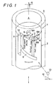
- a head 2 of a plunger 1 can rotate and reciprocate within a plunger barrel 3.
- Fuel from a high-pressure plunger chamber (fuel pressure chamber) 4 is passed through a fuel outlet 5 and emitted from a fuel injection nozzle (not shown).
- a fuel port 6 is provided in the barrel 3.
- the plunger head 2 is provided with a longitudinal groove 7 which connects the plunger chamber to a sloping lower lead 8 also formed in the head 2.
- This lower lead 8 is for controlling the fuel injection end timing. Specifically, the amount of fuel that is injected is controlled by the rotation in either direction of the plunger 1 which, by raising the plunger 1 and thus changing the period of communication between the lower lead 8 and the fuel port 6, adjusts the effective fuel injection stroke.
- the upper part of the orifice flat 10 opens into the plunger chamber 4.
- the relationship between the width F of the flat 10 and the width L of the upper lead 9 is L>F.
- the widths F and L are therefore set at values which ensure the required orifice effect of the flat 10 is attained during the delivery of the fuel accompanying the elevation of the plunger 1.
- the descent of the plunger 1 thus configured causes fuel to be sucked through the fuel port 6 into the plunger chamber 4. Compression of the fuel for the injection process starts when as a result of the elevation of the plunger 1 the upper face 1A and upper lead 9 reach the upper edge 6A, closing the fuel port 6, and the release pressure of the fuel injection nozzle valve is exceeded.
- the prestroke of the plunger 1 is defined as the distance between the bottom dead center of the plunger and the point at which the upper face 1A and upper lead 9 reach the top edge 6A of the fuel port 6.
- the continuing rise of the plunger 1 brings the lower edge 6B of the fuel port 6 to the position of the lower lead 8, thereby connecting the fuel port 6 to the longitudinal groove 7 and stopping the fuel injection.
- the timing of this termination of the fuel injection is controlled by the operation of a fuel injection amount control rack 13 linked to an accelerator 12 to change the rotational position of the plunger 1 relative to the barrel 3, i.e. the relative positional relationship between the fuel port 6 and the lower lead 8.
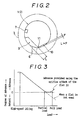
- This also changes the position of the upper lead 9 relative to the fuel port 6, so that when pressing the accelerator 12 is used to rotate the plunger 1 to the left (with reference to Figure 1), the result is that the plunger 1 prestroke is lengthened, retarding the fuel injection timing. This means that, as indicated by Figure 3, increasing the engine load retards the fuel injection timing.
- the ridge line 11 is set as the zero advance point, and when this is exceeded by full-load engine operation, the timing is advanced by the orifice effect of the flat 10, as indicated by the solid line.
- the broken line in Figure 3 indicates the retardation state in the case of a conventional plunger not having a flat 10; this shows that retardation is increased with the increase in the engine load.
- the timing can be advanced even during full-load operation, so engine recovery is rapid.
Landscapes
- Engineering & Computer Science (AREA)
- Chemical & Material Sciences (AREA)
- Combustion & Propulsion (AREA)
- Mechanical Engineering (AREA)
- General Engineering & Computer Science (AREA)
- Fuel-Injection Apparatus (AREA)
- High-Pressure Fuel Injection Pump Control (AREA)
Applications Claiming Priority (2)
| Application Number | Priority Date | Filing Date | Title |
|---|---|---|---|
| JP1990011570U JP2511197Y2 (ja) | 1990-02-09 | 1990-02-09 | 燃料噴射ポンプのプランジャ |
| JP11570/90U | 1990-02-09 |
Publications (2)
| Publication Number | Publication Date |
|---|---|
| EP0441217A1 true EP0441217A1 (de) | 1991-08-14 |
| EP0441217B1 EP0441217B1 (de) | 1993-12-01 |
Family
ID=11781588
Family Applications (1)
| Application Number | Title | Priority Date | Filing Date |
|---|---|---|---|
| EP19910101089 Expired - Lifetime EP0441217B1 (de) | 1990-02-09 | 1991-01-28 | Kolben für eine Kraftstoffeinspritzpumpe |
Country Status (3)
| Country | Link |
|---|---|
| EP (1) | EP0441217B1 (de) |
| JP (1) | JP2511197Y2 (de) |
| DE (1) | DE69100693T2 (de) |
Cited By (1)
| Publication number | Priority date | Publication date | Assignee | Title |
|---|---|---|---|---|
| FR2728025A1 (fr) * | 1994-12-09 | 1996-06-14 | Bosch Gmbh Robert | Pompe d'injection de carburant pour moteur a combustion interne, comprenant plusieurs zones de debut d'injection |
Citations (2)
| Publication number | Priority date | Publication date | Assignee | Title |
|---|---|---|---|---|
| AT311727B (de) * | 1971-11-04 | 1973-11-26 | List Hans | Einspritzpumpe für Dieselmotoren |
| DE3332470A1 (de) * | 1982-09-08 | 1984-03-08 | Steyr-Daimler-Puch AG, 1011 Wien | Kolbeneinspritzpumpe mit schraegkantensteuerung, insbesondere fuer dieselmotoren |
Family Cites Families (2)
| Publication number | Priority date | Publication date | Assignee | Title |
|---|---|---|---|---|
| JPS51146626A (en) * | 1975-05-27 | 1976-12-16 | Hino Motors Ltd | Fuel pump plunger of diesel engine |
| JPS5946363A (ja) * | 1982-09-10 | 1984-03-15 | Diesel Kiki Co Ltd | 燃料噴射ポンプ |
-
1990
- 1990-02-09 JP JP1990011570U patent/JP2511197Y2/ja not_active Expired - Lifetime
-
1991
- 1991-01-28 EP EP19910101089 patent/EP0441217B1/de not_active Expired - Lifetime
- 1991-01-28 DE DE1991600693 patent/DE69100693T2/de not_active Expired - Fee Related
Patent Citations (2)
| Publication number | Priority date | Publication date | Assignee | Title |
|---|---|---|---|---|
| AT311727B (de) * | 1971-11-04 | 1973-11-26 | List Hans | Einspritzpumpe für Dieselmotoren |
| DE3332470A1 (de) * | 1982-09-08 | 1984-03-08 | Steyr-Daimler-Puch AG, 1011 Wien | Kolbeneinspritzpumpe mit schraegkantensteuerung, insbesondere fuer dieselmotoren |
Cited By (1)
| Publication number | Priority date | Publication date | Assignee | Title |
|---|---|---|---|---|
| FR2728025A1 (fr) * | 1994-12-09 | 1996-06-14 | Bosch Gmbh Robert | Pompe d'injection de carburant pour moteur a combustion interne, comprenant plusieurs zones de debut d'injection |
Also Published As
| Publication number | Publication date |
|---|---|
| DE69100693T2 (de) | 1994-03-31 |
| JP2511197Y2 (ja) | 1996-09-18 |
| DE69100693D1 (de) | 1994-01-13 |
| JPH03104169U (de) | 1991-10-29 |
| EP0441217B1 (de) | 1993-12-01 |
Similar Documents
| Publication | Publication Date | Title |
|---|---|---|
| US5219280A (en) | Fuel injection pump plunger | |
| EP0703361B1 (de) | Kraftstoffeinspritzpumpe | |
| US5823168A (en) | Fuel injection pump | |
| EP0441217B1 (de) | Kolben für eine Kraftstoffeinspritzpumpe | |
| JPH0299736A (ja) | ディーゼルエンジンの燃料噴射制御装置 | |
| JPS6255454A (ja) | 燃料噴射ポンプ | |
| JP3296012B2 (ja) | 燃料噴射制御装置 | |
| JPH0650237A (ja) | 燃料噴射ポンプ | |
| JPH04125664U (ja) | 燃料噴射ポンプ | |
| JP2597155B2 (ja) | ディーゼルエンジンの逃孔式燃料噴射ポンプ | |
| JP2597154B2 (ja) | ディーゼルエンジンの逃孔式燃料噴射ポンプ | |
| JP2597157B2 (ja) | ディーゼルエンジンの逃孔式燃料噴射ポンプ | |
| JP2547126Y2 (ja) | 燃料噴射ポンプ | |
| JPS63201361A (ja) | 分配型燃料噴射ポンプ | |
| JP2539064Y2 (ja) | 燃料噴射ポンプ | |
| KR200231110Y1 (ko) | 디젤엔진용 연료분사장치의 분사시기 조절용 배럴의 유로연결구조 | |
| JPS6045748B2 (ja) | 分配型燃料噴射ポンプ | |
| JP2582205Y2 (ja) | 燃料噴射装置 | |
| JP2503393B2 (ja) | 燃料噴射ポンプの噴射量制御装置 | |
| JPH07189862A (ja) | 燃料噴射ポンプ | |
| JP3516583B2 (ja) | ディーゼルエンジンの燃料噴射装置 | |
| JPH0693939A (ja) | 燃料噴射ポンプ | |
| JPS6255455A (ja) | 燃料噴射ポンプ | |
| JPH07189861A (ja) | 燃料噴射ポンプ | |
| JPH0614465U (ja) | 燃料噴射ポンプ |
Legal Events
| Date | Code | Title | Description |
|---|---|---|---|
| PUAI | Public reference made under article 153(3) epc to a published international application that has entered the european phase |
Free format text: ORIGINAL CODE: 0009012 |
|
| 17P | Request for examination filed |
Effective date: 19910128 |
|
| AK | Designated contracting states |
Kind code of ref document: A1 Designated state(s): DE GB |
|
| 17Q | First examination report despatched |
Effective date: 19920414 |
|
| GRAA | (expected) grant |
Free format text: ORIGINAL CODE: 0009210 |
|
| AK | Designated contracting states |
Kind code of ref document: B1 Designated state(s): DE GB |
|
| REF | Corresponds to: |
Ref document number: 69100693 Country of ref document: DE Date of ref document: 19940113 |
|
| PLBE | No opposition filed within time limit |
Free format text: ORIGINAL CODE: 0009261 |
|
| STAA | Information on the status of an ep patent application or granted ep patent |
Free format text: STATUS: NO OPPOSITION FILED WITHIN TIME LIMIT |
|
| 26N | No opposition filed | ||
| PGFP | Annual fee paid to national office [announced via postgrant information from national office to epo] |
Ref country code: DE Payment date: 19991231 Year of fee payment: 10 |
|
| PGFP | Annual fee paid to national office [announced via postgrant information from national office to epo] |
Ref country code: GB Payment date: 20000126 Year of fee payment: 10 |
|
| PG25 | Lapsed in a contracting state [announced via postgrant information from national office to epo] |
Ref country code: GB Free format text: LAPSE BECAUSE OF NON-PAYMENT OF DUE FEES Effective date: 20010128 |
|
| GBPC | Gb: european patent ceased through non-payment of renewal fee |
Effective date: 20010128 |
|
| PG25 | Lapsed in a contracting state [announced via postgrant information from national office to epo] |
Ref country code: DE Free format text: LAPSE BECAUSE OF NON-PAYMENT OF DUE FEES Effective date: 20011101 |