EP0441428A1 - Gerät für Registrierung und/oder Ablesung von Information - Google Patents
Gerät für Registrierung und/oder Ablesung von Information Download PDFInfo
- Publication number
- EP0441428A1 EP0441428A1 EP91200180A EP91200180A EP0441428A1 EP 0441428 A1 EP0441428 A1 EP 0441428A1 EP 91200180 A EP91200180 A EP 91200180A EP 91200180 A EP91200180 A EP 91200180A EP 0441428 A1 EP0441428 A1 EP 0441428A1
- Authority
- EP
- European Patent Office
- Prior art keywords
- head
- record carrier
- distance
- condition
- preload
- Prior art date
- Legal status (The legal status is an assumption and is not a legal conclusion. Google has not performed a legal analysis and makes no representation as to the accuracy of the status listed.)
- Withdrawn
Links
- 230000036316 preload Effects 0.000 claims abstract description 48
- 230000008878 coupling Effects 0.000 claims description 13
- 238000010168 coupling process Methods 0.000 claims description 13
- 238000005859 coupling reaction Methods 0.000 claims description 13
- 230000003213 activating effect Effects 0.000 description 2
- 238000006073 displacement reaction Methods 0.000 description 2
- 230000002349 favourable effect Effects 0.000 description 2
- 230000002411 adverse Effects 0.000 description 1
- 238000010420 art technique Methods 0.000 description 1
- 230000001419 dependent effect Effects 0.000 description 1
- 230000000694 effects Effects 0.000 description 1
- 239000011159 matrix material Substances 0.000 description 1
Images
Classifications
-
- B—PERFORMING OPERATIONS; TRANSPORTING
- B41—PRINTING; LINING MACHINES; TYPEWRITERS; STAMPS
- B41J—TYPEWRITERS; SELECTIVE PRINTING MECHANISMS, i.e. MECHANISMS PRINTING OTHERWISE THAN FROM A FORME; CORRECTION OF TYPOGRAPHICAL ERRORS
- B41J25/00—Actions or mechanisms not otherwise provided for
- B41J25/304—Bodily-movable mechanisms for print heads or carriages movable towards or from paper surface
- B41J25/312—Bodily-movable mechanisms for print heads or carriages movable towards or from paper surface with print pressure adjustment mechanisms, e.g. pressure-on-the paper mechanisms
Definitions
- the present invention relates to an aaparatus for recording information on a record carrier and/or reading information from the same, comprising a recording and/or reading head, means for movable supporting of the head in a direction from or towards the record carrier to adjust the recording and/or reading distance, means for preloading against the record carrier and means for maintaining a distance between the record carrier and the front of the head.
- Apparatus of this kind is particularly suitable for use as printers, but do not exclude another kind of recording and/or reading.
- the head is given a constant distance to the print bed independent of the thickness of the document up to the thickness when the first distance means take over the distance adjustment of the head.
- the distance of the head to the record carrier varies dependent on the thickness of the document and that no contact is present between the head and the document.
- the prior art apparatus has some disadvantages.
- the thickness of the document may vary substantially.
- the printing may take place under conditions applicable for thin documents while printing in other cases takes place under conditions applicable for thick documents.
- the apparatus during the printing of the document may pass between a condition for printing of thin documents and a condition for printing of thick documents.
- Such possible passages may give rise to disturbances in the printing at the passage itself and differences in the printing in the finished document between sections printed under conditions for this documents and sections printed under conditions for thick documents.
- the means for preloading comprise first preloading means acting between the head and the distance means to obtain a first preload against the record carrier in a first condition and second preloading means acting between the head and the means for supporting of the head to obtain a second preload against the record carrier in a second condition, the second preload being higher than the first.
- a first and a second preload of the head against the record carrier are obtained admitting, for example, that thin documents and documents with printing copies may be printed under the pressure of the first lower preload to avoid markes on the document, while documents of the bank-book kind may be printed under the second higher preload giving a better following of the pages of the bank-book.
- the apparatus admitting recording and/or reading at the same distance from the record carrier under the two conditions having different preloads
- the apparatus is characterized in a switch for switching between the first condition having a first preload of the head towards the record carrier and the second condition having a second preload towards the record carrier, the switch under the second condition delimiting the movement of the distance means and defining a constant distance between the record carrier and the front of the head when said distance means are pressed under the influence of said second preloading means.
- the apparatus is characterized in that the switch consists of a slide displaceable in a plane parallel to the record carrier, the surface facing the record carrier comprising at least one higher and one lower section, in the second condition with the second preload the higher section delimiting the movement of the distance means in a direction towards the head to define a constant distance between the record carrier and the front of the head.
- the higher section of the slode provides a simple delimiting of the movement of the distance means at the same time as the head assumes a suitable constant distance to the record carrier under the second preload.
- the slide may be rendered switchable through the movement of the head to a region outside its recording region.
- An apparatus having such a switching may be characterized in that the switch is arranged to be switched between the first condition with the first preload and the second condition with the second preload by means of a movement of the head essentially in parallel with the record carrier to a position outside the recording region of the record carrier, a movement to a position outside one flank of the recording region providing a switching to the first condition, a movement to a position outside the other flank of the recording region providing a switching to the second condition.
- the apparatus for movable supporting the head the apparatus according to an embodiment is characterized in that the means for moveable supporting of the head comprise coupling means coupled between the head and a drive motor, the coupling means under the first condition taking care of the second preload.
- the second preload which is taken care of by the coupling means under the first condition with a first preload prevents that recoils that may arise when activating the head, for example, when activating needles in a needle printing head adversely influences the head.
- Another task is to keep the coupling means in a well-defined position in which the influence of a possible play is prevented.
- the coupling means according to the above embodiment advantageously comprise a link arm coupled between the head and a cam curve on the drive motor shaft.
- the apparatus is thereby more specifically characterized in that the coupling means comprise a link arm which in one of its ends is pivotally coupled to the head and in the other end is provided with a runner, which under the first condition runs along a cam curve provided on the drive motor shaft and which under the second condition is disengaged from the cam curve.
- the cooperation between the runner of the link arm and the cam curve under the first condition keeps the head on an essentially constant distance from the record carrier via the link arm and nullifies the effect of the second preload at the same time as the first preload is free to operate. Information about the distance is obtained from a sensor. Under the second condition the link arm is disengaged from the cam curve and the head is preloaded with the second preload.
- the distance means are provided on a pivotal arm.
- the arm is coupled to a sensor sensing the position of the arm relative to the head.
- a spring included in the first preloading means operates on the arm.
- the embodiment is characterized in that the distance means are provided in one end of an essentially in the center pivorally journalled arm, the other end of which is included in a sensor sensing the position of the arm relative to the head, an in the first preloading means comprised spring being arranged to operate between the arm and a relative to the head fixed point to preload the distance means against the record carrier via the arm.
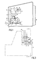
- fig 1 shows a side view of an apparatus according to the invention
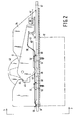
- fig 2 in more detail according to 2-2 in fig 1 shows the coupling of the distance means to the head
- fig 3 shows a side view according to 3-3 in fig 2 of the coupling of the distance means to the head.
- the apparatus for recording information on a record carrier and/or reading the same is provided with an envelope 1 having an input/output opening 2 for a record carrier 3.
- the envelope 1 is shown in the figure with one side wall removed.
- the envelope contains two roll pairs each having a feed roll 4 and 5, respectively, and a pressure roll 6 and 7, respectively.
- a rpint bar 8 is schematically shown between the front roll pair 4, 6 and the rear roll pair 5, 7.
- Two parallel rods 9, 10 perpendicular to the plane of the drawing support a carriage 11 with a head 12.
- the carriage comprises i.e. a base plate 13 which is displaceable on the rods 9, 10 to obtain a displacement parallel to the record carrier 3.
- the head 12 is supported by the base plate 13 by means of two pairs of leaf springs, one pair 14 and 15 being visible in fig 1.
- the leaf springs are attached in projecting sections of the head 12, one section 30 being visible in fig 1, and projecting sections on the base plate 13, one section 32 being visible in fig 1.
- a stiff arm 18 sticks up from the base plate 13.
- a spring 20 is attached between the upper end of the stiff arm 18 and the head 12. The spring acts as a pressure spring between the arm and the head and gives the head a preload in a direction towards the record carrier 3 or the print bar 8.
- distance means 40 in the shape of a roll are indicated.
- a plate 21 is arranged perpendicular to the base plate 13.
- A, not shown, drive motor preferably a step motor, may be fixed to this plate 21.
- the drive motor is thereby coupled to the head 12 through a cam curve 23 arranged on the drive shaft, the cam curve cooperating with a wheel 24 in one end of the link arm 25, the other end of which is pivotally attached to the head.
- a link arm 26 which is pivotally journalled in the plate 21 in one of its ends and in the center of the wheel 24 in the other end, keeps the link arm 25 and the wheel 24 in position for cooperation between the wheel 24 and the cam curve 23.
- Fig 2 and 3 in more detail show the coupling of the distance means to the head, the head 12 being indicated by means of broken lines.
- the distance means consist of a roll 40 which is rotatably journalled in one end of an arm 41.
- the other end of the arm 41 is included in a sensor 42 for registration of the head distance to the record carrier.
- the arm 41 is rotatably journalled around a shaft 43.
- the shaft is fixed in a support element 34, which by means of screws 51, 52 is fixed to the head 12.
- the support element 34 consists of two walls in parallel 35, 36 and a bottom section 37 in between. In fig 2 one of the parallel walls 36 is deleted in accordance with the indication 4-4 in fig 3.
- the shaft 43 is supported by the two parallel walls 35 and 36.
- the movement of the arm 41 towards the record carrier is restricted by means of a lip 45 on the support element 34.
- the lip 45 thereby cooperates with a projecting tongue 46 in the head end of the arm.
- the movement of the arm 41 is restricted in a direction from the record carrier by means of a displaceable slide 47 cooperating with a projecting section 48 of the arm. Due to the fact that the slide 47 is displaceable between two positions, the slide may be given different thickness right before the projecting section 48 of the arm and thereby the movement of the arm from the record carrier may be restricted more or less.
- a leaf spring 50 fixed in the head 12 by means of screws 51 and 52 and distance elements 53 and 54, preloads the arm 41 in a direction towards the record carrier by in one end engaging a head 55 formed in the sensor end of the arm 41.
- the other end of the spring is provided with a bent section 56 for cooperation with a head 57 on the slide 47.
- the slide comprises oblong opening 58, 59 restricting the displacement of the slide.
- the slide In fig 2 the slide is in its right position in which further movement to the right is prevented by means of the left ends of the oblong openings abutting on the left section of the distance elements.
- the head 57 in cooperation with the bent section 56 keep the slide fixed in the shown right position.
- the movement of the slide IN the left position of the slide the movement of the slide is restricted to the right in a corresponding way as for the right position by cooperation between the distance elements and the right sections of the openings and by cooperation between the head 57 and the bent section 56 the slide is held fixed in its left position.
- the slide 47 is switched from the shown right position to the left position by moving the head to the right to a position outside the recording region of the head and in which the right end of the slide hits a, not shown, stop.
- the stop may consist of a, not shown, rotatable end plate carrying one end of two parallel rods 9, 10 on which the carriage 11 is displaceable.
- the switching from the left position of the slide to the right position takes place in a corresponding way by moving the head to the left to a position outside the recording region of the head within which the head hits a, not shown, stop displacing the slide to the right position.
- the head Before the head is transported to a position outside the recording region of the head to the left or to the right, the head suitably is displaced backwards by means of the drive motor driven cam curve 23.
- the arm 41 will thereby rest on the head 45 through the tongue 46 under the influence of the spring 50 when the slide is switched. This prevents unnecessary wear at the recess 49 of the slide 47.
- the slide is switched to the right position shown in the figure with the recess 49 in the slide just opposite the projecting section 48 of the arm 41.
- Printing under a lower preload is suitable in thin documents and printing copies.
- the switching may be carried out according to the description above.
- the head is held at a distance from the record carrier by using the distance information from the sensor 42 by means of the cam curve 23 which via the wheel 24 and the link arm 25 determines the head position.
- the cam curve is driven by a, not shown, motor controlled by the distance information from the sensor.
- the distance to which the cam curve adjust is such that the arm is in a position in which it neighter engages with the lip 45 on the support element 44 or the recess 49 of the slide 47.
- the head is preloaded against the record carrier under the influence of the spring 50.
- the spring force in forward direction may amount to approximately 1,5 N.
- a suitable distance between the head and the record carrier may be 0.35-0.4 mm when printing is concerned.
- the front section of the distance means may be situated for example 1 mm in front of the head front. Accordingly, when recording under a lower preload, the preload is obtained from the spring 50.
- the distance of the head from the record carrier is adjusted starting from the distance information from the sensor coupled to the arm 41 and the support element 34.
- the wheel 24 on the link arm 25 rests on the cam curve 23 under normal circumstances, but may be disengaged at a certain turning up obstacle at the front of the head while overcomming the force of the pressure spring 20.
- the information about the distance between the head 12 and the record carrier 3 as measured by the sensor 42 may be used in servo control of the cam curve 23.
- the cam curve 23 is adjusted to eliminate the deviation.
- Another way to adjust the distance of the head from the record carrier is the following.
- the head is moved towards the print bar 8 until a predetermined distance from the print bar is reached, which is sensed by the sensor 42 and commonly is the desired distance between the head 12 and the record carrier 3 when printing.
- the head 12 is then moved along a print bar 8 without movement of the head perpendicular the print bar 8 at the same time as the distance information from the sensor is memorized. This means that the print bar shape is read and memorized.
- a record carrier 3 When a record carrier 3 is inserted the head is again moved to a position with the same predetermined distance but now from the record carrier.
- the difference between the distance at a chosen point without an with a record carrier in front of the print bar 8 is calculated.
- the distance between the head 12 and the record carrier 3 is adjusted according to the memorized distance information corrected with the calculated distance difference for the point chosen.
- the spring 20 Even if the spring 50 alone has the responsibility for the preload in the shown right position for the slide 47, the spring 20 has substantial tasks.
- the spring 20 must prevent that recoils occurring when the printing needles of the head is activated disturbingly influence the head. Furthermore the spring 20 keeps the link arm 25 under a well defined tension so that possible plays in the bearing of the link arm do not disturbingly influence the positioning of the head.
Landscapes
- Common Mechanisms (AREA)
- Accessory Devices And Overall Control Thereof (AREA)
Applications Claiming Priority (2)
| Application Number | Priority Date | Filing Date | Title |
|---|---|---|---|
| SE9000373A SE465666B (sv) | 1990-02-02 | 1990-02-02 | Apparat foer uppteckning och/eller avlaesning av information |
| SE9000373 | 1990-02-02 |
Publications (1)
| Publication Number | Publication Date |
|---|---|
| EP0441428A1 true EP0441428A1 (de) | 1991-08-14 |
Family
ID=20378439
Family Applications (1)
| Application Number | Title | Priority Date | Filing Date |
|---|---|---|---|
| EP91200180A Withdrawn EP0441428A1 (de) | 1990-02-02 | 1991-01-30 | Gerät für Registrierung und/oder Ablesung von Information |
Country Status (4)
| Country | Link |
|---|---|
| US (1) | US5149210A (de) |
| EP (1) | EP0441428A1 (de) |
| JP (1) | JPH04212874A (de) |
| SE (1) | SE465666B (de) |
Families Citing this family (3)
| Publication number | Priority date | Publication date | Assignee | Title |
|---|---|---|---|---|
| US5265966A (en) * | 1993-03-05 | 1993-11-30 | Rimage Corporation | Printer linkage |
| US5447379A (en) * | 1994-10-31 | 1995-09-05 | Monarch Marking Systems, Inc. | Portable tag or label printer |
| JPH11245477A (ja) * | 1998-03-02 | 1999-09-14 | Nippon Typewriter Co Ltd | サーマル印字装置 |
Citations (2)
| Publication number | Priority date | Publication date | Assignee | Title |
|---|---|---|---|---|
| EP0213934A2 (de) * | 1985-08-29 | 1987-03-11 | Seiko Epson Corporation | Vorrichtung zur Einstellung eines Druckkopfes |
| EP0336734A2 (de) * | 1988-04-06 | 1989-10-11 | Brother Kogyo Kabushiki Kaisha | Drucker mit einer papierdickenabhängigen Druckwerkeinstellung |
Family Cites Families (9)
| Publication number | Priority date | Publication date | Assignee | Title |
|---|---|---|---|---|
| US3912068A (en) * | 1972-05-03 | 1975-10-14 | Bunker Ramo | Printer having document thickness compensating device |
| DE2318947A1 (de) * | 1973-04-14 | 1974-10-24 | Kienzle Apparate Gmbh | Matrixdrucker |
| US4039069A (en) * | 1974-07-31 | 1977-08-02 | Bunker Ramo Corporation | Magnetic stripe passbook and scanner for document printing apparatus |
| IT1020820B (it) * | 1974-09-18 | 1977-12-30 | Olivetti & Co Spa | Dispositivo di alimentazione auto matica di documenti per macchine contabili o simili |
| US4029193A (en) * | 1975-03-31 | 1977-06-14 | Bunker Ramo Corporation | Printer having a platen with resilient segments |
| JPS5882776A (ja) * | 1981-11-11 | 1983-05-18 | Fujitsu Ltd | プリンタ装置 |
| JPS61179774A (ja) * | 1985-02-06 | 1986-08-12 | Nec Corp | プリンタ装置 |
| JPS6273978A (ja) * | 1985-09-26 | 1987-04-04 | Brother Ind Ltd | 印字装置 |
| JPS62211176A (ja) * | 1986-03-12 | 1987-09-17 | Oki Electric Ind Co Ltd | プリンタ |
-
1990
- 1990-02-02 SE SE9000373A patent/SE465666B/sv not_active IP Right Cessation
-
1991
- 1991-01-30 EP EP91200180A patent/EP0441428A1/de not_active Withdrawn
- 1991-01-30 US US07/647,863 patent/US5149210A/en not_active Expired - Lifetime
- 1991-02-01 JP JP9131461A patent/JPH04212874A/ja active Pending
Patent Citations (2)
| Publication number | Priority date | Publication date | Assignee | Title |
|---|---|---|---|---|
| EP0213934A2 (de) * | 1985-08-29 | 1987-03-11 | Seiko Epson Corporation | Vorrichtung zur Einstellung eines Druckkopfes |
| EP0336734A2 (de) * | 1988-04-06 | 1989-10-11 | Brother Kogyo Kabushiki Kaisha | Drucker mit einer papierdickenabhängigen Druckwerkeinstellung |
Also Published As
| Publication number | Publication date |
|---|---|
| SE9000373L (sv) | 1991-08-03 |
| SE9000373D0 (sv) | 1990-02-02 |
| SE465666B (sv) | 1991-10-14 |
| JPH04212874A (ja) | 1992-08-04 |
| US5149210A (en) | 1992-09-22 |
Similar Documents
| Publication | Publication Date | Title |
|---|---|---|
| EP0313208B1 (de) | Mechanismus für die Papierlage im Tintenstrahldrucker | |
| US4883375A (en) | Printing device | |
| US4575267A (en) | Record media thickness compensating mechanism | |
| JP3488540B2 (ja) | ヘッドギャップ調整機構付印字装置 | |
| JP3449851B2 (ja) | 自動紙厚追従機構を備えたプリンタ | |
| EP0434327B1 (de) | Kombinierte Andruckwalze und Wagenführung für einen Drucker | |
| US5156467A (en) | Printer with media thickness adjustment of platen | |
| US6360657B1 (en) | Printer | |
| US4702629A (en) | Apparatus for adjusting the print head gap in a dot matrix printer | |
| US4210076A (en) | Printing apparatus | |
| JPH06500274A (ja) | 印刷装置 | |
| US4780007A (en) | Record media thickness compensating mechanism | |
| EP0717400B1 (de) | Plattenwiedergabegerät | |
| US6170727B1 (en) | Web having alignment indicia and an associated web feeding and working apparatus | |
| US5149210A (en) | Apparatus for recording and/or reading information | |
| CA1265087A (en) | Single station, dual function printer | |
| US6412995B2 (en) | Printing apparatus and platen with a plurality of impact surfaces | |
| US4944616A (en) | Passbook read/write mechanism | |
| US3945636A (en) | Method for visually adjusting a pinch roll for magnetic card transport system | |
| KR100896022B1 (ko) | 프린터 | |
| JPH04212875A (ja) | 記録及び/又は読取装置 | |
| JPH09193491A (ja) | プリンタ | |
| US4556334A (en) | Unitary guide for platen and print head | |
| EP0437724A1 (de) | Kartendruckvorrichtung | |
| JP2590903B2 (ja) | 印字装置 |
Legal Events
| Date | Code | Title | Description |
|---|---|---|---|
| PUAI | Public reference made under article 153(3) epc to a published international application that has entered the european phase |
Free format text: ORIGINAL CODE: 0009012 |
|
| AK | Designated contracting states |
Kind code of ref document: A1 Designated state(s): CH DE FR GB IT LI SE |
|
| 17P | Request for examination filed |
Effective date: 19920214 |
|
| RAP1 | Party data changed (applicant data changed or rights of an application transferred) |
Owner name: DIGITAL EQUIPMENT CORPORATION |
|
| 17Q | First examination report despatched |
Effective date: 19940125 |
|
| STAA | Information on the status of an ep patent application or granted ep patent |
Free format text: STATUS: THE APPLICATION IS DEEMED TO BE WITHDRAWN |
|
| 18D | Application deemed to be withdrawn |
Effective date: 19940830 |