EP0441519B1 - Verstärkender Faserbogen und Verfahren zur Verstärkung einer Struktur mit dem verstärkenden Faserbogen - Google Patents
Verstärkender Faserbogen und Verfahren zur Verstärkung einer Struktur mit dem verstärkenden Faserbogen Download PDFInfo
- Publication number
- EP0441519B1 EP0441519B1 EP19910300684 EP91300684A EP0441519B1 EP 0441519 B1 EP0441519 B1 EP 0441519B1 EP 19910300684 EP19910300684 EP 19910300684 EP 91300684 A EP91300684 A EP 91300684A EP 0441519 B1 EP0441519 B1 EP 0441519B1
- Authority
- EP
- European Patent Office
- Prior art keywords
- reinforcing
- sheet
- matrix resin
- fibers
- reinforcing fiber
- Prior art date
- Legal status (The legal status is an assumption and is not a legal conclusion. Google has not performed a legal analysis and makes no representation as to the accuracy of the status listed.)
- Expired - Lifetime
Links
Images





Classifications
-
- B—PERFORMING OPERATIONS; TRANSPORTING
- B32—LAYERED PRODUCTS
- B32B—LAYERED PRODUCTS, i.e. PRODUCTS BUILT-UP OF STRATA OF FLAT OR NON-FLAT, e.g. CELLULAR OR HONEYCOMB, FORM
- B32B5/00—Layered products characterised by the non- homogeneity or physical structure, i.e. comprising a fibrous, filamentary, particulate or foam layer; Layered products characterised by having a layer differing constitutionally or physically in different parts
- B32B5/22—Layered products characterised by the non- homogeneity or physical structure, i.e. comprising a fibrous, filamentary, particulate or foam layer; Layered products characterised by having a layer differing constitutionally or physically in different parts characterised by the presence of two or more layers which are next to each other and are fibrous, filamentary, formed of particles or foamed
- B32B5/24—Layered products characterised by the non- homogeneity or physical structure, i.e. comprising a fibrous, filamentary, particulate or foam layer; Layered products characterised by having a layer differing constitutionally or physically in different parts characterised by the presence of two or more layers which are next to each other and are fibrous, filamentary, formed of particles or foamed one layer being a fibrous or filamentary layer
-
- B—PERFORMING OPERATIONS; TRANSPORTING
- B29—WORKING OF PLASTICS; WORKING OF SUBSTANCES IN A PLASTIC STATE IN GENERAL
- B29C—SHAPING OR JOINING OF PLASTICS; SHAPING OF MATERIAL IN A PLASTIC STATE, NOT OTHERWISE PROVIDED FOR; AFTER-TREATMENT OF THE SHAPED PRODUCTS, e.g. REPAIRING
- B29C63/00—Lining or sheathing, i.e. applying preformed layers or sheathings of plastics; Apparatus therefor
- B29C63/0017—Lining or sheathing, i.e. applying preformed layers or sheathings of plastics; Apparatus therefor characterised by the choice of the material
- B29C63/0021—Lining or sheathing, i.e. applying preformed layers or sheathings of plastics; Apparatus therefor characterised by the choice of the material with coherent impregnated reinforcing layers
-
- B—PERFORMING OPERATIONS; TRANSPORTING
- B29—WORKING OF PLASTICS; WORKING OF SUBSTANCES IN A PLASTIC STATE IN GENERAL
- B29C—SHAPING OR JOINING OF PLASTICS; SHAPING OF MATERIAL IN A PLASTIC STATE, NOT OTHERWISE PROVIDED FOR; AFTER-TREATMENT OF THE SHAPED PRODUCTS, e.g. REPAIRING
- B29C70/00—Shaping composites, i.e. plastics material comprising reinforcements, fillers or preformed parts, e.g. inserts
- B29C70/04—Shaping composites, i.e. plastics material comprising reinforcements, fillers or preformed parts, e.g. inserts comprising reinforcements only, e.g. self-reinforcing plastics
- B29C70/06—Fibrous reinforcements only
- B29C70/08—Fibrous reinforcements only comprising combinations of different forms of fibrous reinforcements incorporated in matrix material, forming one or more layers, and with or without non-reinforced layers
- B29C70/083—Combinations of continuous fibres or fibrous profiled structures oriented in one direction and reinforcements forming a two dimensional structure, e.g. mats
-
- B—PERFORMING OPERATIONS; TRANSPORTING
- B29—WORKING OF PLASTICS; WORKING OF SUBSTANCES IN A PLASTIC STATE IN GENERAL
- B29C—SHAPING OR JOINING OF PLASTICS; SHAPING OF MATERIAL IN A PLASTIC STATE, NOT OTHERWISE PROVIDED FOR; AFTER-TREATMENT OF THE SHAPED PRODUCTS, e.g. REPAIRING
- B29C70/00—Shaping composites, i.e. plastics material comprising reinforcements, fillers or preformed parts, e.g. inserts
- B29C70/04—Shaping composites, i.e. plastics material comprising reinforcements, fillers or preformed parts, e.g. inserts comprising reinforcements only, e.g. self-reinforcing plastics
- B29C70/06—Fibrous reinforcements only
- B29C70/08—Fibrous reinforcements only comprising combinations of different forms of fibrous reinforcements incorporated in matrix material, forming one or more layers, and with or without non-reinforced layers
- B29C70/086—Fibrous reinforcements only comprising combinations of different forms of fibrous reinforcements incorporated in matrix material, forming one or more layers, and with or without non-reinforced layers and with one or more layers of pure plastics material, e.g. foam layers
-
- B—PERFORMING OPERATIONS; TRANSPORTING
- B29—WORKING OF PLASTICS; WORKING OF SUBSTANCES IN A PLASTIC STATE IN GENERAL
- B29C—SHAPING OR JOINING OF PLASTICS; SHAPING OF MATERIAL IN A PLASTIC STATE, NOT OTHERWISE PROVIDED FOR; AFTER-TREATMENT OF THE SHAPED PRODUCTS, e.g. REPAIRING
- B29C70/00—Shaping composites, i.e. plastics material comprising reinforcements, fillers or preformed parts, e.g. inserts
- B29C70/04—Shaping composites, i.e. plastics material comprising reinforcements, fillers or preformed parts, e.g. inserts comprising reinforcements only, e.g. self-reinforcing plastics
- B29C70/06—Fibrous reinforcements only
- B29C70/08—Fibrous reinforcements only comprising combinations of different forms of fibrous reinforcements incorporated in matrix material, forming one or more layers, and with or without non-reinforced layers
- B29C70/088—Fibrous reinforcements only comprising combinations of different forms of fibrous reinforcements incorporated in matrix material, forming one or more layers, and with or without non-reinforced layers and with one or more layers of non-plastics material or non-specified material, e.g. supports
-
- B—PERFORMING OPERATIONS; TRANSPORTING
- B29—WORKING OF PLASTICS; WORKING OF SUBSTANCES IN A PLASTIC STATE IN GENERAL
- B29C—SHAPING OR JOINING OF PLASTICS; SHAPING OF MATERIAL IN A PLASTIC STATE, NOT OTHERWISE PROVIDED FOR; AFTER-TREATMENT OF THE SHAPED PRODUCTS, e.g. REPAIRING
- B29C70/00—Shaping composites, i.e. plastics material comprising reinforcements, fillers or preformed parts, e.g. inserts
- B29C70/04—Shaping composites, i.e. plastics material comprising reinforcements, fillers or preformed parts, e.g. inserts comprising reinforcements only, e.g. self-reinforcing plastics
- B29C70/06—Fibrous reinforcements only
- B29C70/10—Fibrous reinforcements only characterised by the structure of fibrous reinforcements, e.g. hollow fibres
- B29C70/16—Fibrous reinforcements only characterised by the structure of fibrous reinforcements, e.g. hollow fibres using fibres of substantial or continuous length
- B29C70/20—Fibrous reinforcements only characterised by the structure of fibrous reinforcements, e.g. hollow fibres using fibres of substantial or continuous length oriented in a single direction, e.g. roofing or other parallel fibres
-
- B—PERFORMING OPERATIONS; TRANSPORTING
- B29—WORKING OF PLASTICS; WORKING OF SUBSTANCES IN A PLASTIC STATE IN GENERAL
- B29C—SHAPING OR JOINING OF PLASTICS; SHAPING OF MATERIAL IN A PLASTIC STATE, NOT OTHERWISE PROVIDED FOR; AFTER-TREATMENT OF THE SHAPED PRODUCTS, e.g. REPAIRING
- B29C70/00—Shaping composites, i.e. plastics material comprising reinforcements, fillers or preformed parts, e.g. inserts
- B29C70/04—Shaping composites, i.e. plastics material comprising reinforcements, fillers or preformed parts, e.g. inserts comprising reinforcements only, e.g. self-reinforcing plastics
- B29C70/28—Shaping operations therefor
- B29C70/40—Shaping or impregnating by compression not applied
- B29C70/50—Shaping or impregnating by compression not applied for producing articles of indefinite length, e.g. prepregs, sheet moulding compounds [SMC] or cross moulding compounds [XMC]
- B29C70/504—Shaping or impregnating by compression not applied for producing articles of indefinite length, e.g. prepregs, sheet moulding compounds [SMC] or cross moulding compounds [XMC] using rollers or pressure bands
-
- B—PERFORMING OPERATIONS; TRANSPORTING
- B32—LAYERED PRODUCTS
- B32B—LAYERED PRODUCTS, i.e. PRODUCTS BUILT-UP OF STRATA OF FLAT OR NON-FLAT, e.g. CELLULAR OR HONEYCOMB, FORM
- B32B5/00—Layered products characterised by the non- homogeneity or physical structure, i.e. comprising a fibrous, filamentary, particulate or foam layer; Layered products characterised by having a layer differing constitutionally or physically in different parts
- B32B5/22—Layered products characterised by the non- homogeneity or physical structure, i.e. comprising a fibrous, filamentary, particulate or foam layer; Layered products characterised by having a layer differing constitutionally or physically in different parts characterised by the presence of two or more layers which are next to each other and are fibrous, filamentary, formed of particles or foamed
- B32B5/24—Layered products characterised by the non- homogeneity or physical structure, i.e. comprising a fibrous, filamentary, particulate or foam layer; Layered products characterised by having a layer differing constitutionally or physically in different parts characterised by the presence of two or more layers which are next to each other and are fibrous, filamentary, formed of particles or foamed one layer being a fibrous or filamentary layer
- B32B5/26—Layered products characterised by the non- homogeneity or physical structure, i.e. comprising a fibrous, filamentary, particulate or foam layer; Layered products characterised by having a layer differing constitutionally or physically in different parts characterised by the presence of two or more layers which are next to each other and are fibrous, filamentary, formed of particles or foamed one layer being a fibrous or filamentary layer another layer next to it also being fibrous or filamentary
-
- B—PERFORMING OPERATIONS; TRANSPORTING
- B32—LAYERED PRODUCTS
- B32B—LAYERED PRODUCTS, i.e. PRODUCTS BUILT-UP OF STRATA OF FLAT OR NON-FLAT, e.g. CELLULAR OR HONEYCOMB, FORM
- B32B7/00—Layered products characterised by the relation between layers; Layered products characterised by the relative orientation of features between layers, or by the relative values of a measurable parameter between layers, i.e. products comprising layers having different physical, chemical or physicochemical properties; Layered products characterised by the interconnection of layers
- B32B7/04—Interconnection of layers
- B32B7/12—Interconnection of layers using interposed adhesives or interposed materials with bonding properties
-
- B—PERFORMING OPERATIONS; TRANSPORTING
- B29—WORKING OF PLASTICS; WORKING OF SUBSTANCES IN A PLASTIC STATE IN GENERAL
- B29C—SHAPING OR JOINING OF PLASTICS; SHAPING OF MATERIAL IN A PLASTIC STATE, NOT OTHERWISE PROVIDED FOR; AFTER-TREATMENT OF THE SHAPED PRODUCTS, e.g. REPAIRING
- B29C63/00—Lining or sheathing, i.e. applying preformed layers or sheathings of plastics; Apparatus therefor
-
- B—PERFORMING OPERATIONS; TRANSPORTING
- B29—WORKING OF PLASTICS; WORKING OF SUBSTANCES IN A PLASTIC STATE IN GENERAL
- B29L—INDEXING SCHEME ASSOCIATED WITH SUBCLASS B29C, RELATING TO PARTICULAR ARTICLES
- B29L2031/00—Other particular articles
- B29L2031/10—Building elements, e.g. bricks, blocks, tiles, panels, posts, beams
-
- B—PERFORMING OPERATIONS; TRANSPORTING
- B32—LAYERED PRODUCTS
- B32B—LAYERED PRODUCTS, i.e. PRODUCTS BUILT-UP OF STRATA OF FLAT OR NON-FLAT, e.g. CELLULAR OR HONEYCOMB, FORM
- B32B2305/00—Condition, form or state of the layers or laminate
- B32B2305/07—Parts immersed or impregnated in a matrix
-
- B—PERFORMING OPERATIONS; TRANSPORTING
- B32—LAYERED PRODUCTS
- B32B—LAYERED PRODUCTS, i.e. PRODUCTS BUILT-UP OF STRATA OF FLAT OR NON-FLAT, e.g. CELLULAR OR HONEYCOMB, FORM
- B32B2305/00—Condition, form or state of the layers or laminate
- B32B2305/08—Reinforcements
-
- Y—GENERAL TAGGING OF NEW TECHNOLOGICAL DEVELOPMENTS; GENERAL TAGGING OF CROSS-SECTIONAL TECHNOLOGIES SPANNING OVER SEVERAL SECTIONS OF THE IPC; TECHNICAL SUBJECTS COVERED BY FORMER USPC CROSS-REFERENCE ART COLLECTIONS [XRACs] AND DIGESTS
- Y10—TECHNICAL SUBJECTS COVERED BY FORMER USPC
- Y10T—TECHNICAL SUBJECTS COVERED BY FORMER US CLASSIFICATION
- Y10T442/00—Fabric [woven, knitted, or nonwoven textile or cloth, etc.]
- Y10T442/10—Scrim [e.g., open net or mesh, gauze, loose or open weave or knit, etc.]
- Y10T442/102—Woven scrim
- Y10T442/133—Inorganic fiber-containing scrim
-
- Y—GENERAL TAGGING OF NEW TECHNOLOGICAL DEVELOPMENTS; GENERAL TAGGING OF CROSS-SECTIONAL TECHNOLOGIES SPANNING OVER SEVERAL SECTIONS OF THE IPC; TECHNICAL SUBJECTS COVERED BY FORMER USPC CROSS-REFERENCE ART COLLECTIONS [XRACs] AND DIGESTS
- Y10—TECHNICAL SUBJECTS COVERED BY FORMER USPC
- Y10T—TECHNICAL SUBJECTS COVERED BY FORMER US CLASSIFICATION
- Y10T442/00—Fabric [woven, knitted, or nonwoven textile or cloth, etc.]
- Y10T442/20—Coated or impregnated woven, knit, or nonwoven fabric which is not [a] associated with another preformed layer or fiber layer or, [b] with respect to woven and knit, characterized, respectively, by a particular or differential weave or knit, wherein the coating or impregnation is neither a foamed material nor a free metal or alloy layer
- Y10T442/2041—Two or more non-extruded coatings or impregnations
- Y10T442/2098—At least two coatings or impregnations of different chemical composition
- Y10T442/2107—At least one coating or impregnation contains particulate material
- Y10T442/2115—At least one coating or impregnation functions to fix pigments or particles on the surface of a coating or impregnation
-
- Y—GENERAL TAGGING OF NEW TECHNOLOGICAL DEVELOPMENTS; GENERAL TAGGING OF CROSS-SECTIONAL TECHNOLOGIES SPANNING OVER SEVERAL SECTIONS OF THE IPC; TECHNICAL SUBJECTS COVERED BY FORMER USPC CROSS-REFERENCE ART COLLECTIONS [XRACs] AND DIGESTS
- Y10—TECHNICAL SUBJECTS COVERED BY FORMER USPC
- Y10T—TECHNICAL SUBJECTS COVERED BY FORMER US CLASSIFICATION
- Y10T442/00—Fabric [woven, knitted, or nonwoven textile or cloth, etc.]
- Y10T442/20—Coated or impregnated woven, knit, or nonwoven fabric which is not [a] associated with another preformed layer or fiber layer or, [b] with respect to woven and knit, characterized, respectively, by a particular or differential weave or knit, wherein the coating or impregnation is neither a foamed material nor a free metal or alloy layer
- Y10T442/2926—Coated or impregnated inorganic fiber fabric
- Y10T442/2992—Coated or impregnated glass fiber fabric
-
- Y—GENERAL TAGGING OF NEW TECHNOLOGICAL DEVELOPMENTS; GENERAL TAGGING OF CROSS-SECTIONAL TECHNOLOGIES SPANNING OVER SEVERAL SECTIONS OF THE IPC; TECHNICAL SUBJECTS COVERED BY FORMER USPC CROSS-REFERENCE ART COLLECTIONS [XRACs] AND DIGESTS
- Y10—TECHNICAL SUBJECTS COVERED BY FORMER USPC
- Y10T—TECHNICAL SUBJECTS COVERED BY FORMER US CLASSIFICATION
- Y10T442/00—Fabric [woven, knitted, or nonwoven textile or cloth, etc.]
- Y10T442/60—Nonwoven fabric [i.e., nonwoven strand or fiber material]
-
- Y—GENERAL TAGGING OF NEW TECHNOLOGICAL DEVELOPMENTS; GENERAL TAGGING OF CROSS-SECTIONAL TECHNOLOGIES SPANNING OVER SEVERAL SECTIONS OF THE IPC; TECHNICAL SUBJECTS COVERED BY FORMER USPC CROSS-REFERENCE ART COLLECTIONS [XRACs] AND DIGESTS
- Y10—TECHNICAL SUBJECTS COVERED BY FORMER USPC
- Y10T—TECHNICAL SUBJECTS COVERED BY FORMER US CLASSIFICATION
- Y10T442/00—Fabric [woven, knitted, or nonwoven textile or cloth, etc.]
- Y10T442/60—Nonwoven fabric [i.e., nonwoven strand or fiber material]
- Y10T442/659—Including an additional nonwoven fabric
- Y10T442/67—Multiple nonwoven fabric layers composed of the same inorganic strand or fiber material
-
- Y—GENERAL TAGGING OF NEW TECHNOLOGICAL DEVELOPMENTS; GENERAL TAGGING OF CROSS-SECTIONAL TECHNOLOGIES SPANNING OVER SEVERAL SECTIONS OF THE IPC; TECHNICAL SUBJECTS COVERED BY FORMER USPC CROSS-REFERENCE ART COLLECTIONS [XRACs] AND DIGESTS
- Y10—TECHNICAL SUBJECTS COVERED BY FORMER USPC
- Y10T—TECHNICAL SUBJECTS COVERED BY FORMER US CLASSIFICATION
- Y10T442/00—Fabric [woven, knitted, or nonwoven textile or cloth, etc.]
- Y10T442/60—Nonwoven fabric [i.e., nonwoven strand or fiber material]
- Y10T442/697—Containing at least two chemically different strand or fiber materials
Definitions
- the present invention relates to a method of reinforcing structures using a reinforcing fiber sheet which can easily be handled at reinforcement sites, such as bridges or elevated roads and to a reinforced fiber sheet for reinforcing structures.
- the present invention also relates to a fiber sheet for reinforcing a structure.
- the method itemized by (2) has a disadvantage in that it requires thermosetting of the prepreg adhered to the portion of the pier to be reinforced at the reinforcement site.
- the cloth employed in the method itemized by (3) is obtained by, for example, plainly or diagonally weaving reinforcing fibers, and is thus characterized in that it is weak at the intersections of warps and wefts. Hence, the cloth cannot assure sufficient reinforcement effect when it is made into a fiber reinforced plastic.
- reinforcing filaments impregnated with matrix resin are wound around the portion of the pier to be reinforced by the filament winding process and then thermoset to make it a fiber reinforced plastic at the site.
- the structures on which this method can be performed are restricted, and expensive equipment is required. Hence, this method is not practical.
- CH-A-365,517 discloses a method of reinforcing a structural element by attaching to a surface of a portion of the structural element to be reinforced a reinforcing fiber assembly in which the reinforcing fibers may be arranged in one direction; the fiber assembly is attached to the structural element by means of an adhesive cf. the preamble of claim 1.
- FR-A-1,282,106 discloses a fiber sheet for use in reinforcing plastics materials comprising a support sheet and fibers in parallel on a surface of the support sheet with an adhesive layer therebetween cf. the preamble of claim 3.
- An object of the present invention is to provide such a reinforcing fiber sheet.
- Another object of the present invention is to provide a method of reinforcing structures using such a reinforcing fiber sheet which can be easily handled at the reinforcement site where structures, such as bridges or elevated roads, are reinforced using fiber reinforced plastics, and which enables reinforcement strength to be increased.
- the present invention provides a method of reinforcing a structure comprising the steps of:
- the present invention provides a fiber sheet for reinforcing a structure comprising a support sheet and reinforcing fibers arranged in one direction on at least one surface of the support sheet with an adhesive layer therebetween, characterised in that the reinforcing fibers are impregnated with a room-temperature setting type matrix resin, a curing agent is included in the matrix resin and a curing accelerator is included in the adhesive layer.
- the reinforcing fibers may be impregnated with the matrix resin by coating the matrix resin on the reinforcing fiber sheet before the reinforcing fiber sheet is attached to the surface of the portion of the structure to be reinforced.
- the reinforcing fibers may be impregnated with the matrix resin by coating the matrix resin on the surface of the structure to be reinforced and then by attaching the reinforcing fiber sheet to the surface of the portion to be reinforced.
- the reinforcing fibers may be impregnated with the matrix resin by attaching the reinforcing fiber sheet to the surface of the structure to be reinforced and then by coating the matrix resin on the reinforcing fiber sheet.
- Fig. 1 is a cross-sectional view of a first reinforcing fiber sheet.
- a reinforcing fiber sheet 1 is composed of a support sheet 2, and reinforcing fibers 4 arranged in one direction on one of the surfaces of the support sheet 2 with an adhesive layer 3 therebetween.
- the reinforcing fiber sheet 1 is hence a unidirectional reinforcing fiber sheet.
- the reinforcing fiber sheet 1 is employed for reinforcement with the reinforcing fibers 4 impregnated with a room-temperature thermosetting type matrix resin at the reinforcement site such as a bridge or an elevated road.
- the support sheet 2 of the reinforcing fiber sheet 1 may be made of a scrim cloth, a glass cloth, a sheet of release paper or a polymer film. Generally, it is not necessary for a resin-penetrable type support sheet 2 to be used. However, when it is desired to impregnate the reinforcing fibers 4 with the matrix resin from the side of the sheet 2, a sheet 2 made of a scrim cloth or a glass cloth is used. To provide a sheet 2 which is flexible and which is strong enough to support the reinforcing fibers 4, the thickness of the sheet 2 is set between 1 and 500 ⁇ m, more preferably, between 5 and 100 ⁇ m.
- any adhesive can be used to form the adhesive layer 3 of the reinforcing fiber sheet 1 so long as it can adhere the reinforcing fibers 4 to the support sheet 2 at least temporarily
- an adhesive made of a resin which exhibits compatibility with respect to the matrix resin is preferably used.
- an adhesive made of an epoxy resin is desirably used.
- the preferred thickness of the adhesive layer 3 is from 5 to 100 ⁇ m, with more preferred thickness being from 10 to 30 ⁇ m.
- An adhesive layer having such a thickness is capable of adhering the reinforcing fibers 4 at least temporarily.
- a plurality of bundles of filaments or reinforcing fibers 4 converged using a sizing agent or due to slight twisting are placed on the adhesive layer 3 and then pressed from above to make the reinforcing fibers 4 slightly unfastened.
- the reinforcing fibers 4 are adhered to the support sheet 2 through the adhesive layer 3 in a state where they are piled in a plurality of layers due to the presence of the sizing agent or due to the twisting and where they are arranged in one direction.
- the unidirectional reinforcing fiber sheet 1 is thus obtained.
- the bundles 4A of fibers 4 may be initially aligned in the longitudinal direction on the support sheet 2 with the adhesive layer 3 therebetween in such a manner that they are close to each other with no gap in the lateral direction, as shown Fig. 2(a), and then pressed from above so that the lower portions thereof can be adhered to the support sheet 2 with the adhesive layer 3, as shown in Fig. 2(b), to provide the reinforcing fibers 4 on the support sheet 2 close to each other in the lateral direction thereof.
- the bundles 4A of fibers 4 may be aligned in the longitudinal direction on the support sheet 2 with the adhesive layer 3 therebetween in such a manner that they are separated from each other in the lateral direction, as shown in Fig. 3 (a), and then pressed from above so that the lower portions thereof can be adhered to the adhesive layer 3, as shown in Fig. 3 (b), to provide the reinforcing fibers 4 on the support sheet 2 apart from each other in the lateral direction thereof.
- the bundles 4A of fibers 4 may be used bundles of fibers, i.e., bundles of filaments, on which filamentation is conducted between the filaments or alternatively bundles of filaments on which filamentation is not conducted between the filaments.
- the degree of pressing of the bundles 4A of fibers 4 is determined by a desired thickness of the plurality of layers of reinforcing fibers 4. In the case of carbon fiber bundle which is about 12000 carbon fiber filaments each having a diameter of 5 to 15 ⁇ m, the carbon fibers may be crushed to a degree which ensures that they have a lateral width of about 5 mm.
- Suitable examples of the reinforcing fibers 4 include pitch type carbon fibers, boron fibers, PAN type carbon fibers, aramid fibers, glass fibers, steel fibers, polyester fibers, and polyethylene fibers.
- the unidirectional reinforcing fiber sheet 1 described above can continuously be manufactured in the manner shown, for example, in Fig. 4.
- the sheet 2 is fed to a pressing portion 39 in which a pair of pressing rollers 38a and 38b are provided separate from each other.
- the fiber bundles 4A of the reinforcing fibers 4 and a sheet of release paper 29 from a release paper roll 30 are fed into the pressing portion 39 where the fiber bundles 4A are aligned on the adhesive layer 3 on the sheet 2 in one direction and then the release paper 29 is placed on the fiber bundles 4A.
- the reinforcing fiber sheet 2 is pressed by means of the pressing rollers 38a, 38b and a support plate (not shown) so as to press the fiber bundles 4A and thereby adhere the slightly unfastened reinforcing fibers 4 to the sheet 2 through the adhesive layer 3.
- the release paper 29 is rolled on a release paper roll 31, and the reinforcing fibers 4 are covered with a cover film 33 supplied from a film supply roll 32, when necessary.
- the reinforcing fiber sheet 1 with the reinforcing fibers 4 arranged in one direction on the support sheet 2 through the adhesive layer 3 is continuously manufactured.
- the obtained sheet 1 is rolled on a sheet roll 34.
- the unidirectionally arranged reinforcing fiber sheet 1 is used for reinforcement with the reinforcing fibers 4 impregnated with the room-temperature setting type matrix resin. Impregnation of the reinforcing fibers 4 is conducted at the reinforcement site.
- An epoxy or unsaturated polyester resin to which a curing agent is added for the purpose of making the resin set at room temperatures is used as the room-temperature setting type matrix resin.
- Reinforcement of structures using the unidirectionally arranged reinforcing fiber sheet 1 is conducted in the manner described below.
- a room-temperature setting type matrix resin is coated on the reinforcing fibers 4 of the unidirectionally arranged reinforcing fiber sheet 1 by means of adequate coating means, such as a roller, a brush or by spraying, at the reinforcement sites of structures, such as bridges or the piers of elevated roads.
- the reinforcing fiber sheet 1 is attached to a portion 15 to be reinforced with the reinforcing fibers 4 facing the portion 15 to be reinforced, as shown in Fig. 5.
- impregnation operation of the matrix resin is further conducted using a hand roller or the like.
- the sheets 1 are covered with a press tape and then left untouched for a while to make the matrix resin set and thereby make the sheet 1 a fiber reinforced plastic. In this way, reinforcement of a structure using the fiber reinforced plastic is performed.
- a room-temperature setting type matrix resin 18 is coated on the portion 15 to be reinforced to a thickness of, for example, about 100 ⁇ m, as shown in Fig. 6, and a desired number of unidirectionally arranged reinforcing fiber sheet 1 are piled and pressed with the reinforcing fibers 4 facing the portion 15 to be reinforced, by which the sheets 1 are attached and at the same time the reinforcing fibers 4 are impregnated with the matrix resin 18.
- the matrix resin may be coated on the support sheet 2 of the previously placed sheet 1.
- the sheets 1 are covered with the press tape, and then left for a while to make the matrix resin set and thereby make the sheets 1 fiber reinforced plastics. In this way, reinforcement of structures using the fiber reinforced plastic is conducted as in the aforementioned case.
- a unidirectionally arranged reinforcing fiber sheet 1 with a resin-penetrable type support sheet 2 is used.
- a resin of the same type as the matrix resin is coated on the portion 15 to be reinforced as a primer 16, and a desired number of sheets 1 are then piled on top of one another on the primer 16.
- the room-temperature setting matrix resin 18 is coated on the support sheet 2 of the outermost sheet 1 e.g. by means of a roller.
- the matrix resin penetrates the sheet 2 and then enters the reinforcing fibers 4.
- the sheets 1 are covered with the press tape, and then left untouched for a while for the matrix resin 18 to set and thereby make the sheets 1 solid fiber reinforced plastics. In this way, reinforcement of structures using the fiber reinforced plastics is conducted, as in the case of the aforementioned cases.
- the reinforced fiber sheet 1 on which the reinforced fibers are arranged on the support sheet 2 in one direction is used.
- the reinforcing fibers 4 are impregnated with a room-temperature setting type matrix resin at a reinforcement site to make the sheet 1 ready for use.
- the sheet 1 impregnated with the matrix resin is attached to the portion to be reinforced and left untouched to make the matrix resin set and thereby make the sheet 1 a fiber reinforced plastic. Consequently, a troublesome work of thermosetting the matrix resin can be eliminated and workability of reinforcement of structures using the fiber reinforced plastics can thus be improved.
- the reinforcing fibers 4 are arranged in one direction, reduction in the strength of the fiber reinforced plastic, which would occur when the reinforcing fibers 4 are woven into a cloth, can be eliminated, and the reinforcement strength can thus be increased. Furthermore, after the sheet 1 is attached to the portion to be reinforced, the matrix resin is set. As a result, the sheet 1 can also be applied to a curved portion to be reinforced.
- the reinforcing fiber sheets 1 are piled one on top of another with the reinforcing fibers 4 facing the portion 15 to be reinforced.
- the reinforcing fiber sheets 1 may also be piled with the support sheet 2 facing the portion 15 to be reinforced.
- the room-temperature setting type matrix resin is left for setting.
- setting of the matrix resin may also be accelerated by heating.
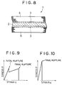
- Fig. 8 is a cross-sectional view of a second reinforced fiber sheet.
- the reinforcing fiber sheet 1 is composed of the support sheet 2, rigid first reinforcing fibers 4 adhered to one of the surfaces of the support sheet 2 through the adhesive layer 3 in a state wherein they are arranged in one direction, and tough second reinforcing fibers 6 adhered on the other surface of the support sheet 2 through the adhesive layer 3 in a state wherein they are arranged in one direction.
- the reinforcing fiber sheet 1 hence employs hybrid reinforcing fibers.
- Other structures of the reinforcing fiber sheet 1 of this embodiment are the same as those of the first embodiment.
- the same reference numerals are therefore used to denote parts which are the same as those shown in Fig. 1.
- the reinforcing fiber sheet 1 is formed as a hybrid sheet by providing the rigid first reinforcing fibers 4 on one of the surfaces of the support sheet 2 and by providing the tough second reinforcing fibers 6 on the other surface of the support sheet 2 for the purpose of increasing the fracture strength or energy and thereby reducing generation of cracks by the presence of the rigid first reinforcing fibers 4 and for the purpose of increasing the fracture toughness of the structure and thereby postponing fracture by the presence of the tough second reinforcing fibers 6 when the reinforcing fiber sheet 1 is used for reinforcing structures in the form of a fiber reinforced plastic.
- Fig. 9 is a graph schematically showing a stress-strain curve of a fiber reinforced plastic which is obtained when a vertical load is applied to the surface of a hybrid fiber reinforced plastic obtained by providing the rigid and tough reinforcing fibers on the two surfaces of the reinforcing fiber sheet.
- Fig. 10 is a graph similar to Fig. 9, showing a stress-strain curve of a fiber reinforced plastic obtained by providing on the two surfaces of the reinforcing fiber sheet one type of reinforcing fibers which are more rigid and less tough than the reinforcing fibers employed in Fig. 9.
- the strain ⁇ is large, as shown in Fig. 9.
- the tough reinforcing fibers stretch greatly and thereby postpones final rupture of the tough reinforcing fibers.
- the fracture energy indicated by the area surrounded by the curve in Fig. 9 is large. That is, the time required for the entirety of the fiber reinforced plastic to rupture is long.
- the use of a hybrid fiber reinforced plastic obtained by using the reinforcing fiber sheet 1 with two types of reinforcing fibers, the rigid reinforcing fibers and the tough reinforcing fibers, increases the fracture energy of the structure and thereby reduces generation of cracks.
- the use of the hybrid fiber reinforced plastic increases the fracture toughness of the structure and thereby postpones fracture after generation of cracks in the structure. It is therefore possible to assure safety of reinforcement of structures using the fiber reinforced plastics.
- first reinforcing fibers 4 having a modulus of elasticity of 44,5 GN/m 2 (5 ton/mm 2 ) or above are preferred.
- Tough second reinforcing fibers 6 having an elongation at rupture of 1.2% or above which is higher than the elongation at rupture of the first reinforcing fibers 4 by 20% or above are preferably used.
- First reinforcing fibers 4 having a modulus of elasticity of less than 44,5 GN/m 2 (5 ton/mm 2 ) cannot sufficiently increase the fracture strength of the structure.
- the reinforcing fibers 4 and 6 may be pitch type carbon fibers, boron fibers, PAN type carbon fibers, aramid fibers, glass fibers, steel fibers, polyester fibers or polyethylene fibers, if they are combined to satisfy the above properties.
- the fiber bundles 4A and 6A of the reinforcing fibers 4 and 6 are aligned on the adhesive layers 3 formed on the two surfaces of the support sheet 2 close to each other or apart from each other, as shown in Figs. 11 (a) and 12 (a), as in the case of the first embodiment.
- Figs. 11 (b) and 12 (b) respectively show the arrangement of the reinforcing fibers 4 and 6 obtained from the alignment of the fiber bundles 4A and 6A shown in Figs. 11 (a) and 12 (a).
- the hybrid reinforcing fiber sheet 1 described above can be manufactured continuously in the manner shown in, for example, Fig. 13.
- the sheet 2 After an adhesive is coated on the two surfaces of the support sheet 2 supplied from the sheet supply roll 26 by means of adhesive coating roll 27a and 27b to form the adhesive layers 3, the sheet 2 is fed into a pressing portion 39.
- the rigid first reinforcing fiber bundles 4A and the tough second reinforcing fiber bundles 6A are respectively fed from reinforcing fiber supply rolls 20a and 20b into the pressing portion 39 where they are aligned in one direction on the adhesive layers 3 on the two surfaces of the sheet 2.
- sheets of release paper 29a and 29b are respectively fed from release paper rolls 30a and 30b into the pressing portion 39 where they are placed on the fiber bundles 4A and 6A.
- the fiber bundles 4A and 6A are pressed and thereby adhered to the respective surfaces of the sheet 2 through the adhesive layers 3 in a slightly unfastened state by means of the pair of pressing rollers 38a and 38b. Thereafter, the sheets of release paper 29a and 29b are respectively rolled on release paper rolls 31a and 31b, by which a hybrid reinforcing fiber sheet 1 with the rigid first reinforcing fibers 4 and the tough second reinforcing fibers 6 respectively disposed on the two surfaces of the support sheet 2 through the adhesive layers 3 in one direction is obtained.
- the reinforcing fiber sheet 1 After the reinforcing fibers 4 and 6 of the reinforcing fiber sheet 1 are respectively covered with cover films 33a and 33b respectively supplied from film supply rolls 32a and 32b, when necessary, the reinforcing fiber sheet 1 is rolled on the sheet roll 34.
- the reinforcing method which uses the reinforcing fiber sheet 1 of this version, a troublesome work of thermosetting the matrix resin at the reinforcement cite can be eliminated, and workability of the reinforcement of structures using the fiber reinforced plastic can thus be enhanced, as in the case of the first method. Furthermore, reinforcement strength can be increased, and reinforcement of a curved portion is made possible.
- the first reinforcing fibers 4 of the reinforcing fiber sheet 1 have a modulus of elasticity of 44,5 GN/m 2 (5 tons/m 2 ) or above while the second reinforcing fibers 6 have an elongation at rupture of 1.2% or above which is higher than the elongation at rupture of the first reinforcing fibers 4 by 20% or above, the use of a resultant hybrid fiber reinforced plastic increases the fracture strength of the structure and thereby reduces generation of cracks due to the presence of the rigid first reinforcing fibers 4 and increases the fracture toughness of the structure and thereby postpones rupture of the structure due to the presence of the tough second reinforcing fibers 6.
- Carbon fibers and polyester fibers (trademark: Vectran, manufactured by Kurare) were respectively used as the rigid first reinforcing fibers and the tough second reinforcing fibers.
- the carbon fibers and the polyester fibers were provided on the respective surfaces of the support sheet at a unit weight of 175 g/m 2 and in one direction thereof to form a hybrid reinforcing fiber sheet.
- the modulus of elasticity of the used carbon fibers was 209,1 GN/m 2 (23.5 ton/mm 2 ) in strand strength measurement method (JIS method), and the elongation thereof was 1.4%.
- the modulus of elasticity of the used polyester fibers was 76,6 GN/m 2 (8.5 ton/mm 2 ), and the elongation thereof was 2.5%.
- a reinforcing fiber sheet was manufactured by providing the carbon fibers employed in the above example on the two surfaces of the support sheet at a unit weight of 175 g/m 2 and in one direction. The carbon fibers were impregnated with the matrix resin and then left to make the matrix resin set. The same tests were conducted.
- Table 1 shows the results of the tests.
- the loads at the initial and final ruptures are the average values of those obtained in the tests conducted seven times, and the elongations are the average values of five values.
- the numerals in round brackets are CV (coefficient of variation) values which indicate the degree of variation.
- the rigidity is the rigidity of the entire fiber reinforced plastic indicated in the form of load/elongation.
- the fracture energy is calculated by triangle approximation from the stress-strain curve similar to those shown in Figs. 9 and 10.
- the hybrid reinforcing fiber sheet with rigid carbon fibers and tough polyester fibers provided thereon is used to obtain a fiber reinforced plastic in the present invention, the elongation and fracture energy are about 2.5 times those of the non-hybrid fiber reinforced plastic obtained from the reinforced fiber sheet with only the carbon fibers provided thereon, although the load at the final rupture is smaller. Consequently, fracture of the reinforcing fibers does not cause immediate final rupture, and safety of the reinforced structures with the fiber reinforced plastics is thus assured.
- Fig. 14 is a cross-sectional view of a third reinforcing fiber sheet 1.
- This reinforcing fiber sheet 1 differs from that of the second version in that the rigid first reinforcing fibers 4 and the tough second reinforcing fibers 6 are provided in one direction on one of the surfaces of the support sheet 2 through the adhesive layer 3.
- Other configurations of this version are the same as those of the second version.
- the fiber bundles 4A and 6A of the reinforcing fibers 4 and 6 are aligned on the adhesive layer 3 formed on one of the two surfaces of the support sheet 2 close to each other or apart from each other, as shown in Figs. 15 (a) and 16 (a), as in the case of the first embodiment.
- Figs. 15 (b) and 16 (b) show the arrangement of the reinforcing fibers 4 and 6 obtained from the alignment of the fiber bundles 4A and 6A shown in Figs. 15 (a) and 16 (a).
- the hybrid reinforcing fiber sheet 1 described above can be manufactured continuously in the manner shown in, for example, Fig. 17.
- the sheet 2 is fed to the pressing portion 39.
- the rigid first reinforcing fiber bundles 4A and the tough second reinforcing fiber bundles 6A are respectively fed from reinforcing fiber supply rolls 20a and 20b into the pressing portion 39 where they are aligned on the adhesive layer 3 in one direction.
- the sheet of release paper 29 is fed from the release paper roll 30 into the pressing portion 39 where the release paper 29 is placed on the fiber bundles 4A and 6A.
- the fiber bundles 4A and 6A are pressed and thereby adhered to the surface of the sheet 2 through the layer of adhesive 3 in a slightly unfastened state by means of the pair of pressing rollers 38a and 38b. Thereafter, the sheet of release paper 29 is rolled on the release paper roll 31, by which the hybrid reinforcing fiber sheet 1 with the rigid first reinforcing fibers 4 and the tough second reinforcing fibers 6 disposed on one surface of the support sheet 2 through the adhesive layer 3 in one direction is obtained.
- the reinforcing fiber sheet 1 After the reinforcing fibers 4 and 6 of the reinforcing fiber sheet 1 are covered with the cover film 33 supplied from film supply roll 32, when necessary, the reinforcing fiber sheet 1 is rolled on the sheet roll 34.
- the reinforcing method which uses the reinforcing fiber sheet 1 of this version, a troublesome work of thermosetting the matrix resin at the reinforcement cite can be eliminated, and workability of the reinforcement of structures using the fiber reinforced plastic can thus be enhanced. Furthermore, reinforcement of a curved portion is made possible. Furthermore, the use of the hybrid reinforcing fiber sheet 1 increases the fracture and toughness strengths of the structure, as in the case of the second version.
- the hybrid reinforcing fiber sheet 1 provided using the rigid first reinforcing fibers and tough second reinforcing fibers is used to obtain a hybrid fiber reinforced plastic.
- the reinforcing fiber sheet 1 (called the first reinforcing fiber sheet) using the rigid first reinforcing fibers 4, shown in Fig. 18 (a), and the reinforcing fiber sheet 1 (called the second reinforcing fiber sheet) employing the tough second reinforcing fibers 6, shown in Fig. 18 (b), are used for reinforcement.
- the first and second reinforcing fiber sheets 1 are respectively unidirectionally arranged reinforcing fiber sheets obtained by respectively providing the reinforcing fibers 4 and 6 on one of the surfaces of the support sheets 2 through the adhesive layers 3 in one direction.
- the reinforcing fibers 4 and 6 employed in this version and other configurations are the same as those of the second and third versions.
- first and second reinforcing fiber sheets 1 are used for reinforcing the structure in a number of at least one from the gist of this reinforcing method.
- first or second reinforcing fiber sheet 1 or both the first and second reinforcing fiber sheets 1 may be used in at least two depending on the degree of reinforcement conducted on the portion to be reinforced.
- the first and second reinforcing fiber sheets 1 are piled alternately or in other ways.
- the reinforcing fiber sheet which is first placed on the portion to be reinforced may be either the first or second reinforcing fiber sheet 1.
- the room-temperature setting type matrix resin is coated on the reinforcing fibers 4 and 6 of the first and second reinforcing fiber sheets 1 by means of adequate coating means, such as a roller, a brush or by spraying, at the reinforcement site of structures, such as bridges or the piers of elevated roads.
- adequate coating means such as a roller, a brush or by spraying
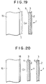
- the first and second reinforcing fiber sheets 1 are attached to the portion 15 to be reinforced in a desired order and in a desired number with the reinforcing fibers 4 and 6 facing the portion 15 to be reinforced, as shown in Fig. 19.
- the reinforcing fiber sheets are covered with the press tape and then left untouched to set the matrix resin and thereby make the first and second reinforcing fiber sheets 1 fiber reinforced plastics. In this way, reinforcement of a structure using the hybrid fiber reinforced plastic obtained from the first and second reinforcing fiber sheets 1 is performed.
- a room-temperature setting type matrix resin 18 is coated on the portion 15 to be reinforced to a thickness of, for example, about 100 ⁇ m, as shown in Fig. 20. Thereafter, a desired number of first and second reinforcing fiber sheets 1 are piled and pressed with the reinforcing fibers 4 and 6 facing the portion to be reinforced 15, by which the sheets 1 are attached and at the same time the reinforcing fibers 4 and 6 are impregnated with the matrix resin 18.
- the support sheet 2 is not the resin-penetrable type, each time the sheet 1 is placed on the previously placed sheet 1, the matrix resin may be coated on the support sheet 2 of the previously placed sheet 1.
- first and second reinforcing fiber sheets 1 are covered with the press tape, and then left for a while to make the matrix resin set and thereby make the first and second reinforcing fiber sheets 1 fiber reinforced plastics. In this way, reinforcement of structures using the hybrid fiber reinforced plastic is conducted as in the aforementioned case.
- first and second reinforcing fiber sheets 1 with the resin-penetrable type support sheets 2 are used.
- a resin of the same type as the matrix resin is coated on the portion 15 to be reinforced as a primer 16, and a desired number of first and second reinforcing fiber sheets 1 are then piled on top of another on the primer 16.
- the room-temperature setting matrix resin 18 is coated on the outermost sheet 1 by means of a roller or the like. The matrix resin penetrates the sheets 2 and then enters the reinforcing fibers 4 and 6.
- first and second reinforcing fiber sheets 1 are covered with the press tape and then left untouched for a while to make the matrix resin 18 set and thereby make the first and second reinforcing fiber sheets 1 fiber reinforced plastics. In this way, reinforcement of structures using the hybrid fiber reinforced plastics is conducted, as in the case of the aforementioned cases.
- Carbon fibers were provided on the support sheet as the rigid first reinforcing fibers at a unit weight of 175 g/m 2 and in one direction to manufacture the first reinforcing fiber sheet.
- Polyester fibers (trademark: Vectran, manufactured by Kurare) were provided on the support sheet as the tough second reinforcing fibers at a unit weight of 175 g/m 2 and in one direction to manufacture the second reinforcing fiber sheet.
- the modulus of elasticity of the used carbon fibers was 209.1 GN/m 2 (23.5 ton/mm 2 ) in strand strength measurement method (JIS method), and the elongation thereof was 1.4%.
- the modulus of elasticity of the used polyester fibers was 76,6 GN/m 2 (8.5 ton/mm 2 ), and the elongation thereof was 2.5%.
- the first and second reinforcing fiber sheets were impregnated with the matrix resin which was a room-temperature setting type epoxy resin, the first and second reinforcing fiber sheets were adhered to each other and left at room temperatures to make the matrix resin set, by which the hybrid fiber reinforced plastic was obtained.
- Samples of the obtained fiber reinforced plastic had a width of 15 mm. Tests were conducted by applying a vertical load to the samples to measure the loads and elongations at the initial and final ruptures and thereby examine the effect of the fiber reinforced plastic made from the unidirectionally oriented reinforcing fiber sheets.
- reinforcing fiber sheets were manufactured by providing the carbon fibers employed in the above example on the support sheets at a unit weight of 175 g/m 2 and in one direction. The carbon fibers were impregnated with the matrix resin. Thereafter, the reinforcing fiber sheets were adhered with each other and then left to make the matrix resin set. The same tests were conducted on the samples.
- Table 2 shows the results of the tests.
- the loads at the initial and final fractures are the average values of those obtained in the tests conducted seven times, and the elongations are the average values of five values.
- the numerals in round brackets are CV (coefficient of variation) values which indicate the degree of variation.
- the rigidity is the rigidity of the entire fiber reinforced plastic indicated in the form of load/elongation.
- the fracture energy is calculated by triangle approximation from the stress-strain curve similar to those shown in Figs. 9 and 10.
- An embodiment of the invention is characterized in that a curing accelerator agent for accelerating the setting of the room-temperature setting type matrix resin is present in the adhesive layer 3 of the reinforcing fiber sheet 1 which is the same as that of the first example described with reference to Fig. 1. Setting of the matrix resin is conducted due to the presence of the curing agent.
- Other configurations of the reinforcing fiber sheet 1 of this example are the same as those of the reinforcing fiber sheet 1 of the first embodiment.
- curing agent and curing accelerator are added to the matrix resin.
- the curing agent and curing accelerator are present in the room-temperature setting type matrix resin used in the first to fourth examples also.
- a curing accelerator is added not to the matrix resin but to the adhesive layer 3 of the reinforcing fiber sheet 1.
- the room-temperature setting type matrix resin remains unset until the matrix resin is impregnated with the reinforcing fibers 4 of the reinforcing fiber sheet 1 and the room-temperature curing agent present in the matrix resin is thereby mixed with the curing accelerator present in the adhesive layer 3 of the reinforcing fiber sheet 1. Consequently, the pot life of the matrix resin can be prolonged, and handling of the resin can thus be facilitated. As a result, reinforcement work needs not be hastened with setting of the matrix resin taken into consideration, and workability can further be improved. Once the reinforcing fibers 4 are impregnated with the room-temperature type matrix resin and the curing agent is thereby mixed with the curing accelerator, the setting reaction progresses and the matrix resin thus sets rapidly. Therefore, there is no problem involving the setting of the matrix resin.
- the curing accelerator is adequately made depending on the type of matrix resin or curing agent added to the matrix resin.
- an unsaturated polyester type resin such as unsaturated polyester resin or vinyl ester resin
- a peroxide type curing agent such as methyl ethyl ketone peroxide
- a cobalt type curing accelerator such as cobalt naphthenate
- the room-temperature setting type matrix resin remains unset until the matrix resin is impregnated with the reinforcing fibers 4 of the reinforcing fiber sheet 1 and the room-temperature curing agent present in the matrix resin is thereby mixed with the curing accelerator present in the adhesive layer 3 of the reinforcing fiber sheet 1, handling of the resin can be facilitated, and reinforcement work needs not be hastened with setting of the matrix resin taken into consideration. This improves workability of the reinforcement work.
- one type of reinforcing fibers 4 is used.
- two types of reinforcing fibers, the rigid reinforcing fibers 4 and the tough reinforcing fibers 6, may also be used to provide a hybrid reinforcing fiber sheet, as in the cases shown in Figs. 8 and 14.
- the pot life of the matrix resin can be prolonged and handling of the matrix resin used for reinforcing structures can thus be facilitated by adding the curing accelerator for accelerating setting of the room-temperature setting type matrix resin to the adhesive layer 3 of each reinforcing fiber sheet 1.
- reinforcing fiber sheets (called reinforcing fiber sheets with a curing accelerator therein) were manufactured by providing glass fibers (GF) on the resin films on the support sheets.
- the obtained reinforcing GF sheets were impregnated with the room-temperature setting type matrix resin which was an unsaturated polyester type resin to estimate the setting characteristics (amount of remaining styrene) and thereby examine the effect of presence of the curing accelerator for the room-temperature setting type matrix resin in the adhesive layer of the reinforcing fiber sheet according to the present invention.
- the unit weight of glass fibers in the reinforcing GF sheet was 350 g/m 2 .
- Epoxy resin film with the curing accelerator agent added thereto was a resinous solution in which Epikote 1001, Epikote 828 and 8% Nodex CO were present in a weight ratio of 73 : 7 : 20. This epoxy resin film with the curing accelerator added thereto was coated at a unit weight of 18 g/m 2 .
- EPIKOTE and NODEX are Registered Trade Marks.
- the glass fibers of the reinforcing GF sheet were impregnated with the matrix resin by laminating on a PET film first the matrix resin, then reinforcing GF sheet, the matrix resin again, the reinforcing GF sheet again and finally the matrix resin.
- the matrix resin was left for eight days at room temperatures.
- a reinforcing GF sheet (normally used reinforcing fiber sheet) was manufactured by providing glass fibers on the adhesive layer on the support sheet.
- the adhesive layer was the epoxy resin film to which no curing accelerator was added.
- the glass fibers were impregnated with the matrix resin in which cobalt naphthenene was present as the curing accelerator to estimate the setting characteristics of the matrix resin.
- the glass fibers of the reinforcing fiber sheet were also impregnated with the matrix resin in which no cobalt naphthenate was present to examine the setting characteristics of that matrix resin.
- Table 3 shows the results of the examinations.
- Example Nos. 1 and 2 since the curing accelerator agent was added not to the matrix resin but to the adhesive layer, the pot life of the matrix resin increased to ten hours, like the case of Comparative Example No. 5, and the impregnation operation of the reinforcing fibers with the matrix resin, which was conducted by the lamination of the reinforcing GF sheets and the matrix resin, had not be hastened. Furthermore, since the matrix resin was left at room temperatures for eight days for setting, the amount of remaining styrene reduced to 2.3 to 3.2 wt%, which showed excellent setting of the matrix resin, as in the cases of Comparative Example Nos. 3 and 4 in which the curing accelerator agent was added to the matrix resin (in which the amount of styrene remaining in the matrix resin was 1.7 to 2.1 wt%).
- the room-temperature setting type matrix resin is impregnated with the reinforcing fibers 4 at the reinforcement site.
- the curing accelerator for accelerating setting of the matrix resin is added not to the matrix resin but to the adhesive layer 3 of the reinforcing fiber sheet 1 in this embodiment, the pot life of the matrix resin can be prolonged, and handling thereof can thus be improved.
- the reinforcing fiber sheets described above are used for reinforcing structures, the reinforcing fibers thereof are impregnated with the matrix resin at the reinforcement site, and then the reinforcing fiber sheet is placed on the portion to be reinforced and then left as it is to make it a fiber reinforced plastic. Consequently, workability of reinforcement work of structures, such as bridges or elevated roads, can be enhanced. Furthermore, since the reinforcing fiber sheet is a sheet on which reinforcing fibers are arranged in one direction, the resultant fiber reinforced plastic ensures increased reinforcement strength. Furthermore, since the curing accelerator for accelerating setting of the matrix resin is added not to the matrix resin but to the adhesive layer of the reinforcing fiber sheet, the pot life of the matrix resin can be prolonged, and workability of the reinforcement work is thus further improved.
Landscapes
- Engineering & Computer Science (AREA)
- Chemical & Material Sciences (AREA)
- Composite Materials (AREA)
- Mechanical Engineering (AREA)
- Textile Engineering (AREA)
- Manufacturing & Machinery (AREA)
- Reinforced Plastic Materials (AREA)
- Working Measures On Existing Buildindgs (AREA)
- Laminated Bodies (AREA)
Claims (3)
- Verfahren zum Verstärken einer Struktur, welches folgenden Schritt umfaßt: Befestigen mindestens eines verstärkenden Faserbogens (1), der einen Tragbogen (2) und verstärkende Fasern (4) aufweist, welche in einer Richtung zumindest auf einer Oberfläche des Tragbogens (2) mit einer dazwischenliegenden Klebstoffschicht (3) angeordnet sind, an einer Oberfläche eines zu verstärkenden Abschnittes der Struktur (15), gekennzeichnet durch den weiteren Schritt des Aushärtens eines bei Raumtemperatur härtenden Matrixharzes (18), mit welchem die verstärkenden Fasern imprägniert sind, wobei in dem bei Raumtemperatur härtenden Matrixharz (18) ein Härtemittel enthalten ist und in der Klebstoffschicht (3) ein Härtungsbeschleuniger enthalten ist.
- Verfahren zum Verstärken einer Struktur nach Anspruch 1, bei welchem die verstärkenden Fasern (4) dadurch mit dem Matrixharz imprägniert sind, daß a) das Matrixharz (18) auf den verstärkenden Faserbogen (1) aufgetragen wird, bevor der verstärkende Faserbogen an der Oberfläche des Abschnittes der zu verstärkenden Struktur (15) angebracht wird, oder b) das Matrixharz (18) auf die Oberfläche der zu verstärkenden Struktur (15) aufgetragen wird und dann der verstärkende Faserbogen (1) an der Oberfläche des zu verstärkenden Abschnittes befestigt wird, oder c) der verstärkende Faserbogen (1) an der Oberfläche der zu verstärkenden Struktur (15) befestigt wird und dann das Matrixharz (18) auf den verstärkenden Faserbogen (1) aufgetragen wird.
- Faserbogen zum Verstärken einer Struktur mit einem Tragbogen (1) und verstärkenden Fasern (4), die in einer Richtung auf mindestens einer Oberfläche des Tragbogens mit einer dazwischen liegenden Klebstoffschicht (3) angeordnet sind, dadurch gekennzeichnet, daß die verstärkenden Fasern (4) mit einem bei Raumtemperatur aushärtenden Matrixharz (18) imprägniert sind und in dem Matrixharz (18) ein Härtemittel enthalten ist und in der Klebstoffschicht (3) ein Härtungsbeschleuniger enthalten ist .
Priority Applications (1)
| Application Number | Priority Date | Filing Date | Title |
|---|---|---|---|
| EP96200172A EP0723855B1 (de) | 1990-01-30 | 1991-01-30 | Verfahren zur Verstärkung einer Struktur mit einem verstärkenden Faserbogen |
Applications Claiming Priority (9)
| Application Number | Priority Date | Filing Date | Title |
|---|---|---|---|
| JP19928/90 | 1990-01-30 | ||
| JP19927/90 | 1990-01-30 | ||
| JP2019927A JP2869931B2 (ja) | 1990-01-30 | 1990-01-30 | 一方向配列強化繊維シート及びその製造方法 |
| JP2019928A JP2819333B2 (ja) | 1990-01-30 | 1990-01-30 | 構築物の補強方法 |
| JP2094436A JPH03292110A (ja) | 1990-04-10 | 1990-04-10 | 一方向配列ハイブリッド強化繊維シート、その製造方法及び構築物の補強方法 |
| JP2094438A JP2851680B2 (ja) | 1990-04-10 | 1990-04-10 | 構築物の補強方法 |
| JP2094437A JPH03292111A (ja) | 1990-04-10 | 1990-04-10 | 一方向配列ハイブリッド強化繊維シート、その製造方法及び構築物の補強方法 |
| JP2275049A JPH04149366A (ja) | 1990-10-12 | 1990-10-12 | 強化繊維シート及び構築物の補強方法 |
| CA 2071097 CA2071097C (en) | 1990-01-30 | 1992-06-12 | Reinforcing fiber sheet, method of manufacturing the same, and method of reinforcing structure with the reinforcing fiber sheet |
Related Child Applications (2)
| Application Number | Title | Priority Date | Filing Date |
|---|---|---|---|
| EP96200172A Division EP0723855B1 (de) | 1990-01-30 | 1991-01-30 | Verfahren zur Verstärkung einer Struktur mit einem verstärkenden Faserbogen |
| EP96200172.3 Division-Into | 1991-01-30 |
Publications (2)
| Publication Number | Publication Date |
|---|---|
| EP0441519A1 EP0441519A1 (de) | 1991-08-14 |
| EP0441519B1 true EP0441519B1 (de) | 1996-11-06 |
Family
ID=27560966
Family Applications (1)
| Application Number | Title | Priority Date | Filing Date |
|---|---|---|---|
| EP19910300684 Expired - Lifetime EP0441519B1 (de) | 1990-01-30 | 1991-01-30 | Verstärkender Faserbogen und Verfahren zur Verstärkung einer Struktur mit dem verstärkenden Faserbogen |
Country Status (3)
| Country | Link |
|---|---|
| US (2) | US5308430A (de) |
| EP (1) | EP0441519B1 (de) |
| CA (1) | CA2071097C (de) |
Cited By (6)
| Publication number | Priority date | Publication date | Assignee | Title |
|---|---|---|---|---|
| GB2295637A (en) * | 1994-12-02 | 1996-06-05 | Sho Bond Corp | Strengthening a reinforced concrete structure |
| US5635263A (en) * | 1993-09-28 | 1997-06-03 | Tonen Corporation | Reinforcing fiber sheet and concrete structure using same |
| EP0994223A1 (de) | 1998-10-13 | 2000-04-19 | Lino Credali | Armierungsgewebe für Bauwerke |
| US6183835B1 (en) | 1997-08-27 | 2001-02-06 | Moon Soo Cho | Manufacturing method of reinforced fiber sheet useful for repairing/reinforced concrete structure |
| US6269599B1 (en) | 1995-12-05 | 2001-08-07 | Josef Scherer | Construction component or construction with a composite structure, associated composite construction element, and method of production |
| RU2681861C2 (ru) * | 2014-01-10 | 2019-03-13 | Осв Интеллекчуал Капитал, Ллк | Безуточные однонаправленные ткани, армированные волокном |
Families Citing this family (25)
| Publication number | Priority date | Publication date | Assignee | Title |
|---|---|---|---|---|
| EP0378232B1 (de) * | 1989-01-12 | 1993-04-28 | Mitsubishi Kasei Corporation | Verfahren zur Verstärkung von Betonstrukturen |
| EP0598591A3 (en) * | 1992-11-17 | 1994-08-10 | Tonen Corp | Fibre-reinforced sheet for reinforcement. |
| IT1266176B1 (it) * | 1994-07-19 | 1996-12-23 | Foggini Progetti | Procedimento di fabbricazione di materiale per elementi di pannellatura ornamentale, particolarmente per autovetture, e |
| JPH08128211A (ja) * | 1994-10-28 | 1996-05-21 | Tonen Corp | コンクリート床版の補強方法 |
| AU4900796A (en) * | 1995-02-21 | 1996-09-11 | Minnesota Mining And Manufacturing Company | Adhesive sheet articles |
| FR2747146B1 (fr) * | 1996-04-04 | 1998-07-10 | Freyssinet Int Stup | Procede de renforcement de structures de genie civil au moyen de fibres de carbone collees |
| DE19717942A1 (de) * | 1997-04-29 | 1998-11-05 | Butz Peter Verwaltung | Kopfstütze für Fahrzeugsitze |
| US5908685A (en) * | 1997-05-29 | 1999-06-01 | The Goodyear Tire & Rubber Company | Elastomeric composite structure |
| EP0904928A1 (de) * | 1997-09-26 | 1999-03-31 | Cho, Moon Soo | Verfahren zur Herstellung eines faserverstärkten Bogens verwendbar zum Reparieren/Verstärken einer Betonstruktur |
| US6418684B1 (en) | 1999-02-16 | 2002-07-16 | Engineered Composite Systems, Inc. | Wall reinforcement apparatus and method using composite materials |
| FR2790500B1 (fr) | 1999-03-01 | 2002-06-07 | Freyssinet Int Stup | Procede et dispositif de renforcement d'un ouvrage en beton |
| EP1160072A3 (de) * | 2000-05-30 | 2002-11-06 | Nippon Steel Composite Co., Ltd. | Kontinuierliche, mit Fasern verstärkte Folie und Verfahren zu deren Herstellung |
| TWI225116B (en) * | 2000-06-29 | 2004-12-11 | Nippon Oil Corp | Structure reinforcing method, structure-reinforcing reinforcing fiber yarn-containing material, reinforcing structure material and reinforced structure |
| US6767625B2 (en) * | 2002-12-30 | 2004-07-27 | Owens Corning Fiberglas Technology, Inc. | Method for making a charge of moldable material |
| ITPD20070200A1 (it) † | 2007-06-08 | 2008-12-09 | Angeloni S R L G | Rinforzo fibroso del tipo rinforzo per materiale composito |
| US20100038003A1 (en) * | 2007-10-29 | 2010-02-18 | Jean Carlos Gracia | Method and apparatus for sealing a wheel rim |
| US20090120557A1 (en) * | 2007-11-12 | 2009-05-14 | Serra Jerry M | system for reinforcing and monitoring support members of a structure and methods therefor |
| US20100078259A1 (en) * | 2008-09-30 | 2010-04-01 | Honeywell International Inc. | Flowbodies and methods of forming flowbodies |
| WO2010045100A2 (en) * | 2008-10-15 | 2010-04-22 | 3M Innovative Properties Company | Reinforcement patches with unidirectionally-aligned fibers |
| EP2998100A1 (de) | 2010-05-13 | 2016-03-23 | Structural Group, Inc. | System und verfahren zur reparatur und stärkung eines rohrs mit einer inneren spiralförmig gewundenen spannungsverstärkung |
| US8567146B2 (en) * | 2010-09-29 | 2013-10-29 | Garland Industries, Inc. | Method and apparatus for repairing concrete |
| US8584431B2 (en) | 2011-01-13 | 2013-11-19 | Robert Luke Secrest | Carbon fiber wall reinforcement system and a method for its use |
| US10647084B2 (en) | 2014-11-25 | 2020-05-12 | The Boeing Company | Multi-layer plies for improved composite performance |
| USD979385S1 (en) | 2020-10-20 | 2023-02-28 | Garland Industries, Inc. | Concrete connector |
| USD1085857S1 (en) | 2020-10-20 | 2025-07-29 | Garland Industries, Inc. | Concrete connector |
Family Cites Families (16)
| Publication number | Priority date | Publication date | Assignee | Title |
|---|---|---|---|---|
| FR1091813A (fr) * | 1953-10-16 | 1955-04-15 | Procédé de fabrication d'objets en matière plastique armée de fils et objets ainsi fabriqués | |
| CH365517A (fr) * | 1960-08-11 | 1962-11-15 | Berthier Georges | Procédé de renforcement d'un élément de construction en matériau pierreux |
| FR1282106A (fr) * | 1960-12-08 | 1962-01-19 | Chaîne ourdie destinée au renforcement de matières plastiques | |
| US3624073A (en) * | 1967-09-06 | 1971-11-30 | Hoffmann La Roche | Process for preparing 5-substituted-1,4-benzodiazepines |
| JPS5528842A (en) * | 1978-08-21 | 1980-02-29 | Kurashiki Boseki Kk | Dressing sheet and its preparation |
| FI801415A7 (fi) * | 1979-05-05 | 1980-11-06 | Arthur Britton | Arkmaterial |
| DE3132697A1 (de) * | 1981-08-19 | 1983-03-03 | Richard 4937 Lage Pott | Verfahren und vorrichtung zur herstellung eines geleges |
| JPS5884879A (ja) * | 1981-11-16 | 1983-05-21 | Sugawara Kogyo Kk | 粘着テ−プ |
| JPS58122860A (ja) * | 1982-01-14 | 1983-07-21 | 松下電工株式会社 | 金属箔張積層板の製法 |
| US4435470A (en) * | 1982-04-12 | 1984-03-06 | North Shore Laboratories Corporation | Repair material for tubeless tires |
| US4604319B1 (en) * | 1984-06-01 | 1995-07-04 | American Cyanamid Co | Thermoplastic interleafed resin matrix composites with improved impact strength and toughness |
| GB8627786D0 (en) * | 1986-11-20 | 1986-12-17 | Tech Textiles Ltd | Composite material |
| US4983453A (en) * | 1987-09-04 | 1991-01-08 | Weyerhaeuser Company | Hybrid pultruded products and method for their manufacture |
| US4997693A (en) * | 1987-11-20 | 1991-03-05 | Asahi Glass Company, Ltd. | Fiber-reinforced resin material and fiber-reinforced resin laminate using it as base material |
| US4868035A (en) * | 1988-05-16 | 1989-09-19 | Weinberg Martin J | Electrical insulating materials made partly or wholly of polyester film |
| US5722536A (en) * | 1996-02-08 | 1998-03-03 | Bausch & Lomb Incorporated | Disposable contact lens package with snap-together feature |
-
1991
- 1991-01-28 US US07/646,572 patent/US5308430A/en not_active Expired - Lifetime
- 1991-01-30 EP EP19910300684 patent/EP0441519B1/de not_active Expired - Lifetime
-
1992
- 1992-06-12 CA CA 2071097 patent/CA2071097C/en not_active Expired - Fee Related
-
1993
- 1993-03-15 US US08/031,436 patent/US5326630A/en not_active Expired - Lifetime
Cited By (7)
| Publication number | Priority date | Publication date | Assignee | Title |
|---|---|---|---|---|
| US5635263A (en) * | 1993-09-28 | 1997-06-03 | Tonen Corporation | Reinforcing fiber sheet and concrete structure using same |
| GB2295637A (en) * | 1994-12-02 | 1996-06-05 | Sho Bond Corp | Strengthening a reinforced concrete structure |
| GB2295637B (en) * | 1994-12-02 | 1998-07-29 | Sho Bond Corp | Method for strengthening a reinforced concrete structure |
| US6269599B1 (en) | 1995-12-05 | 2001-08-07 | Josef Scherer | Construction component or construction with a composite structure, associated composite construction element, and method of production |
| US6183835B1 (en) | 1997-08-27 | 2001-02-06 | Moon Soo Cho | Manufacturing method of reinforced fiber sheet useful for repairing/reinforced concrete structure |
| EP0994223A1 (de) | 1998-10-13 | 2000-04-19 | Lino Credali | Armierungsgewebe für Bauwerke |
| RU2681861C2 (ru) * | 2014-01-10 | 2019-03-13 | Осв Интеллекчуал Капитал, Ллк | Безуточные однонаправленные ткани, армированные волокном |
Also Published As
| Publication number | Publication date |
|---|---|
| US5326630A (en) | 1994-07-05 |
| CA2071097A1 (en) | 1993-12-13 |
| US5308430A (en) | 1994-05-03 |
| EP0441519A1 (de) | 1991-08-14 |
| CA2071097C (en) | 1999-02-16 |
Similar Documents
| Publication | Publication Date | Title |
|---|---|---|
| US5308430A (en) | Reinforcing fiber sheet, method of manufacturing the same, and the method of reinforcing structure with the reinforcing fiber sheet | |
| EP0056288B1 (de) | Schichtstoff aus Metallblech und aus damit verbundenen Fäden und Verfahren zu ihrer Herstellung | |
| US7087296B2 (en) | Energy absorbent laminate | |
| EP0056289B1 (de) | Schichtstoff aus Aluminiumschichten und Polyaramidfasern | |
| CA2132460C (en) | Reinforcing fiber sheet and concrete structure using same | |
| US11834855B2 (en) | Laminate material for reinforcement, reinforcing method, and reinforcing structural body for structure | |
| EP0552370A1 (de) | Kohlenfaser-prepreg und kohlenfasen-verstärktes harz | |
| US5552214A (en) | Unidirectional prepreg and carbon fiber reinforced composite materials comprising pitch-based carbon fibers and polyacrylonitrile-based carbon fibers | |
| EP0723855B1 (de) | Verfahren zur Verstärkung einer Struktur mit einem verstärkenden Faserbogen | |
| JP3405497B2 (ja) | 構造物補強用強化繊維シート | |
| JPH1199580A (ja) | 一方向性繊維強化複合材用素材及びその製造方法 | |
| JPH0978848A (ja) | コンクリート構造物の補強方法およびそれに用いるコンクリート構造物補強用シート | |
| KR0170401B1 (ko) | 강화 섬유 시이트, 그의 제조방법 | |
| JP2869931B2 (ja) | 一方向配列強化繊維シート及びその製造方法 | |
| JP2851680B2 (ja) | 構築物の補強方法 | |
| EP0598591A2 (de) | Zur Armierung geeignete, faserverstärkte Folie | |
| JP3174358B2 (ja) | 一方向配列強化繊維シート及び構築物の補強方法 | |
| JPH032224A (ja) | ハイブリッドプリプレグ | |
| JPH0531839A (ja) | 一方向配列強化繊維シート | |
| JPH07164545A (ja) | Frp中空成形品及びそれに用いる繊維強化材構成 | |
| JPH04149366A (ja) | 強化繊維シート及び構築物の補強方法 | |
| JPH06193280A (ja) | 一方向配列強化繊維シートによるコンクリート補修方法 | |
| JPH03292110A (ja) | 一方向配列ハイブリッド強化繊維シート、その製造方法及び構築物の補強方法 | |
| JPH09254299A (ja) | プリプレグ材 | |
| JPH0825495A (ja) | Frp中空部材の引抜き成形法 |
Legal Events
| Date | Code | Title | Description |
|---|---|---|---|
| PUAI | Public reference made under article 153(3) epc to a published international application that has entered the european phase |
Free format text: ORIGINAL CODE: 0009012 |
|
| AK | Designated contracting states |
Kind code of ref document: A1 Designated state(s): DE FR GB IT |
|
| 17P | Request for examination filed |
Effective date: 19920123 |
|
| 17Q | First examination report despatched |
Effective date: 19930803 |
|
| GRAG | Despatch of communication of intention to grant |
Free format text: ORIGINAL CODE: EPIDOS AGRA |
|
| GRAG | Despatch of communication of intention to grant |
Free format text: ORIGINAL CODE: EPIDOS AGRA |
|
| GRAH | Despatch of communication of intention to grant a patent |
Free format text: ORIGINAL CODE: EPIDOS IGRA |
|
| GRAH | Despatch of communication of intention to grant a patent |
Free format text: ORIGINAL CODE: EPIDOS IGRA |
|
| GRAH | Despatch of communication of intention to grant a patent |
Free format text: ORIGINAL CODE: EPIDOS IGRA |
|
| GRAA | (expected) grant |
Free format text: ORIGINAL CODE: 0009210 |
|
| ITF | It: translation for a ep patent filed | ||
| AK | Designated contracting states |
Kind code of ref document: B1 Designated state(s): DE FR GB IT |
|
| XX | Miscellaneous (additional remarks) |
Free format text: TEILANMELDUNG 96200172.3 EINGEREICHT AM 25/01/96. |
|
| ET | Fr: translation filed | ||
| REF | Corresponds to: |
Ref document number: 69122976 Country of ref document: DE Date of ref document: 19961212 |
|
| PLBE | No opposition filed within time limit |
Free format text: ORIGINAL CODE: 0009261 |
|
| STAA | Information on the status of an ep patent application or granted ep patent |
Free format text: STATUS: NO OPPOSITION FILED WITHIN TIME LIMIT |
|
| 26N | No opposition filed | ||
| REG | Reference to a national code |
Ref country code: FR Ref legal event code: CA Ref country code: FR Ref legal event code: TP |
|
| REG | Reference to a national code |
Ref country code: GB Ref legal event code: 732E |
|
| REG | Reference to a national code |
Ref country code: GB Ref legal event code: IF02 |
|
| PGFP | Annual fee paid to national office [announced via postgrant information from national office to epo] |
Ref country code: FR Payment date: 20060110 Year of fee payment: 16 |
|
| PGFP | Annual fee paid to national office [announced via postgrant information from national office to epo] |
Ref country code: GB Payment date: 20060125 Year of fee payment: 16 |
|
| PGFP | Annual fee paid to national office [announced via postgrant information from national office to epo] |
Ref country code: DE Payment date: 20060126 Year of fee payment: 16 |
|
| PGFP | Annual fee paid to national office [announced via postgrant information from national office to epo] |
Ref country code: IT Payment date: 20060131 Year of fee payment: 16 |
|
| PG25 | Lapsed in a contracting state [announced via postgrant information from national office to epo] |
Ref country code: DE Free format text: LAPSE BECAUSE OF NON-PAYMENT OF DUE FEES Effective date: 20070801 |
|
| GBPC | Gb: european patent ceased through non-payment of renewal fee |
Effective date: 20070130 |
|
| REG | Reference to a national code |
Ref country code: FR Ref legal event code: ST Effective date: 20070930 |
|
| PG25 | Lapsed in a contracting state [announced via postgrant information from national office to epo] |
Ref country code: GB Free format text: LAPSE BECAUSE OF NON-PAYMENT OF DUE FEES Effective date: 20070130 |
|
| PG25 | Lapsed in a contracting state [announced via postgrant information from national office to epo] |
Ref country code: FR Free format text: LAPSE BECAUSE OF NON-PAYMENT OF DUE FEES Effective date: 20070131 |
|
| PG25 | Lapsed in a contracting state [announced via postgrant information from national office to epo] |
Ref country code: IT Free format text: LAPSE BECAUSE OF NON-PAYMENT OF DUE FEES Effective date: 20070130 |