EP0442429B1 - Parachute de sûreté pour chariot guidé sur une balustrade - Google Patents
Parachute de sûreté pour chariot guidé sur une balustrade Download PDFInfo
- Publication number
- EP0442429B1 EP0442429B1 EP91101901A EP91101901A EP0442429B1 EP 0442429 B1 EP0442429 B1 EP 0442429B1 EP 91101901 A EP91101901 A EP 91101901A EP 91101901 A EP91101901 A EP 91101901A EP 0442429 B1 EP0442429 B1 EP 0442429B1
- Authority
- EP
- European Patent Office
- Prior art keywords
- catch lever
- catch
- lever arm
- rungs
- valley
- Prior art date
- Legal status (The legal status is an assumption and is not a legal conclusion. Google has not performed a legal analysis and makes no representation as to the accuracy of the status listed.)
- Expired - Lifetime
Links
Images

Classifications
-
- B—PERFORMING OPERATIONS; TRANSPORTING
- B66—HOISTING; LIFTING; HAULING
- B66B—ELEVATORS; ESCALATORS OR MOVING WALKWAYS
- B66B9/00—Kinds or types of lifts in, or associated with, buildings or other structures
- B66B9/06—Kinds or types of lifts in, or associated with, buildings or other structures inclined, e.g. serving blast furnaces
- B66B9/08—Kinds or types of lifts in, or associated with, buildings or other structures inclined, e.g. serving blast furnaces associated with stairways, e.g. for transporting disabled persons
- B66B9/0807—Driving mechanisms
- B66B9/0815—Rack and pinion, friction rollers
Definitions
- the invention relates to a safety device for a guided on a railing carriage, on which a two-armed, pivotally mounted catch lever is provided, which stops the carriage by swiveling against bars arranged transversely to the direction of travel on the railing at impermissibly high speed.
- a safety device for an elevator in which rotatable pendulums are attached to the side of the elevator floor, which are pivoted out when the elevator moves up or down by hitting curved elevations on the guide rails. If a predetermined maximum speed is reached during the downward movement of the elevator, the pendulums cannot return to their normal position quickly enough and then hit protrusions on the guide rail by which the elevator is stopped.
- This known device is complex and costly due to the high number of curved elevations and the additional projections required and cannot be set to different response speeds.
- the invention has for its object to show a simpler solution for a safety device for a slide guided on a railing, which also allows an advantageous setting to different response speeds.
- the object is achieved by the features specified in the characterizing part of patent claim 1. Further features are listed in the subclaims. An embodiment of the invention will now be explained on a stair lift with a load-carrying device designed as a platform or seat with reference to the drawings.
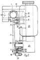
- the railing for guiding the load-bearing device - hereinafter referred to briefly as a carriage - essentially consists of a stable guide tube 1 (FIG. 1), a toothed rack 5 guided close above the floor 2 or the steps 3 and arranged between the guide tube 1 and the toothed rack 5 Rungs 7, which have the same distances in their upper area.
- a guide cage 10 is mounted on a pivot axis 12 on the base plate 9 of the sled, which carries a person seat or a platform for a disabled lift (not shown).
- Four guide rollers 14, which are adapted to the diameter of the guide tube 1, are rotatably mounted in the guide cage 10 and allow safe and smooth guidance of the slide on the guide railing.
- the carriage is supported in its lower section in the region of the rack 5 (FIG. 2) and driven at the same time.
- the rack 5 is covered over its entire length on its side facing the steps by a screen 16 (not shown in FIG. 1).
- a screen 16 (not shown in FIG. 1).
- An electric motor 22 drives a gear wheel 24 which engages in the toothed rack via a gear 23 and which has a lateral guide on the screen 16.
- the carriage is supported by an upper support roller 26 on the outside of the screen 16.
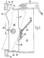
- the massive catch lever 28 (FIGS. 2 and 3) is pivotably mounted on two bearing plates 30, which are fixedly connected to the base plate 9, and has a length which corresponds approximately to the mean distance between two rungs 7.
- the two-armed catch lever 28 is held in the position shown in solid lines in FIG. 3 by a tension spring 34, which is fastened on the one hand to a holding pin 35 of the one bearing plate 30 and on the other hand is suspended in one of the holes in the row of holes 36.
- an acute-angled recess 40 is incorporated, which guarantees that the catch lever arm 39 securely engages on the rung 7a.
- an extension 43 is provided which, when the catch lever 28 is pivoted into the latching position, serves a switch 44 for switching off the power supply to the electric motor 22 (FIG. 1) and possibly for triggering an alarm signal.
- the mountain-side catch lever arm 41 has on its side facing the rungs 7 a cam-like projection 45 which pivots the catch lever 28 when the slide descends on each rung 7 in such a way that the valley-side catch lever arm 39 enters the space between the next rung 7.
- the maximum angle of the pivoting-in process is determined by the maximum increase in the projection 45 when sliding along the long side 46 of the rung 7. As soon as the apex of the projection 45 leaves the longitudinal side 46 of the rung 7 during the downward movement in the direction of arrow 32, the return movement of the catch lever 28 will start under the action of the tension spring 34. Because of the inertia of the relatively massive catch lever 28, a certain time is required for the pivoting back of the catch lever, since this movement begins after the release of the projection on the rung 7 at zero and increases with the acceleration determined by the force of the tension spring 34. However, if the speed of the downward movement is greater than the defined normal speed, the catch lever 28 will not have left the area between the rungs 7 and 7a (FIG. 3) and will apply it to the rung 7a and assume the position shown in broken lines in FIG.
- the main advantage of the safety device according to the invention is the particularly cost-effective and reliable design solution, which does not require any additional monitoring device.
Landscapes
- Engineering & Computer Science (AREA)
- Mechanical Engineering (AREA)
- Transportation (AREA)
- Automation & Control Theory (AREA)
- Structural Engineering (AREA)
- Types And Forms Of Lifts (AREA)
Claims (5)
- Parachute de sureté pour chariot guidé sur une balustrade auquel est prévu une clenche à deux bras pivotant transversalement au sens de marche, qui, en cas de vitesse inadmissiblement augmentée, arrêtera le chariot en pivotant contre des éparts disposés à la balustrade transversalement au sens de marche, caractérisé par ce quea) un ressort de traction (34) agit sur la clenche (28) excentriquement à son axe de pivotement de telle façon que la partie face (38) du bras de clenche (39), côté vallée, puisse pivoter dans la zone des éparts (7), soit contre l'action du ressort de traction (34),b) le bras de clenche (41), côté montagne, présente, au côté vis-à-vis des éparts (7), une saillie (43) similaire à une came qui, en cas de descente, fait pivoter la clenche (28) à chaque épart (7) de telle façon que le bras de clenche (39), côté vallée, entre dans l'espace devant le prochain épart (7), etc) le ressort de traction (34) a été dimensionné de telle façon que le pivotement en retour de la clenche (28), effectué par le ressort de traction, est tellement retardé par son inertie de masse que lors du dépassement de la vitesse normale, le bras de clenche (39), côté vallée, atteindra encore le prochain épart.
- Parachute de sureté selon revendication 1, caractérisé par ce que la partie face (38) du bras de clenche (39), côté vallée, présente un évidement acutangulé (40).
- Parachute de sureté selon les revendications 1 et 2, caractérisé par ce qu'en la zone centrale de la clenche (28), excentrique par rapport au pivot (31), plusieurs alésages ont été disposés en file, alésages faisant partie d'une rangée de trous (36) et prévus pour la fixation du ressort.
- Parachute de sureté selon les revendications 1 à 3, caractérisé par ce que la partie face (42) du bras de clenche (41), côté montagne, présente un prolongement (43) actionnant un interrupteur (44) en position d'arrêt de la clenche.
- Parachute de sureté selon les revendications 1 à 4, caractérisé par ce que la longueur de la clenche (28) correspond à la distance moyenne des éparts (7).
Applications Claiming Priority (2)
| Application Number | Priority Date | Filing Date | Title |
|---|---|---|---|
| DE4004190 | 1990-02-12 | ||
| DE4004190 | 1990-02-12 |
Publications (3)
| Publication Number | Publication Date |
|---|---|
| EP0442429A2 EP0442429A2 (fr) | 1991-08-21 |
| EP0442429A3 EP0442429A3 (en) | 1992-02-19 |
| EP0442429B1 true EP0442429B1 (fr) | 1994-11-30 |
Family
ID=6399927
Family Applications (1)
| Application Number | Title | Priority Date | Filing Date |
|---|---|---|---|
| EP91101901A Expired - Lifetime EP0442429B1 (fr) | 1990-02-12 | 1991-02-11 | Parachute de sûreté pour chariot guidé sur une balustrade |
Country Status (2)
| Country | Link |
|---|---|
| EP (1) | EP0442429B1 (fr) |
| DE (1) | DE59103604D1 (fr) |
Cited By (1)
| Publication number | Priority date | Publication date | Assignee | Title |
|---|---|---|---|---|
| CN102936959A (zh) * | 2012-11-28 | 2013-02-20 | 无锡威华电焊机制造有限公司 | 钢筋桁架节间距调整装置 |
Families Citing this family (1)
| Publication number | Priority date | Publication date | Assignee | Title |
|---|---|---|---|---|
| US6659230B1 (en) * | 2000-01-17 | 2003-12-09 | Stannah Stairlifts Limited | Safety brake for stairlifts |
Family Cites Families (4)
| Publication number | Priority date | Publication date | Assignee | Title |
|---|---|---|---|---|
| US4046226A (en) * | 1976-07-08 | 1977-09-06 | Flinchbaugh-Murray Corporation | Elevator system for transporting wheelchair patients |
| DE2719120C2 (de) * | 1977-04-29 | 1987-08-20 | Kleindienst GmbH, 8900 Augsburg | Lift |
| EP0137577A1 (fr) * | 1983-10-10 | 1985-04-17 | Antony Stopher | Ascenseur d'escalier |
| GB8531094D0 (en) * | 1985-12-18 | 1986-01-29 | Ease Ltd | Stairlift |
-
1991
- 1991-02-11 EP EP91101901A patent/EP0442429B1/fr not_active Expired - Lifetime
- 1991-02-11 DE DE59103604T patent/DE59103604D1/de not_active Expired - Fee Related
Cited By (1)
| Publication number | Priority date | Publication date | Assignee | Title |
|---|---|---|---|---|
| CN102936959A (zh) * | 2012-11-28 | 2013-02-20 | 无锡威华电焊机制造有限公司 | 钢筋桁架节间距调整装置 |
Also Published As
| Publication number | Publication date |
|---|---|
| EP0442429A3 (en) | 1992-02-19 |
| DE59103604D1 (de) | 1995-01-12 |
| EP0442429A2 (fr) | 1991-08-21 |
Similar Documents
| Publication | Publication Date | Title |
|---|---|---|
| DE60306045T2 (de) | Seilrutsche mit statisch vorgespanntem Seil | |
| EP0076974B1 (fr) | Plateforme élévatrice pour personnes | |
| DE69611064T2 (de) | Bewegliches Absturzsicherungsgerät für flexibles Rettungsseil | |
| EP3541734B2 (fr) | Cabine d'ascenseur | |
| DE102011009049A1 (de) | Absturzsicherung für Steiggeräte | |
| DE3606728C2 (fr) | ||
| DE2753445A1 (de) | Sicherheitsvorrichtung fuer eine fahrstuhlanlage | |
| EP3947096A1 (fr) | Pylône de téléphérique comportant un dispositif de passage | |
| EP0745526B1 (fr) | Protection mécanique contre le déraillement d'un cable | |
| CH669181A5 (de) | Vorabschalteinrichtung an einem nockenrad-geschwindigkeitsbegrenzer fuer aufzuege. | |
| EP0640552A1 (fr) | Dispositif de blocage et d'accrochage pour le chariot guidé sur rails d'un ascenseur oblique ou vertical | |
| WO2000060209A1 (fr) | Appareil de capture | |
| EP1514994B1 (fr) | Dispositif de blocage pour système anti-chute | |
| EP2723669B1 (fr) | Ascenseur pour pompiers | |
| EP0442429A2 (fr) | Parachute de sûreté pour chariot guidé sur une balustrade | |
| DE9013718U1 (de) | Fangvorrichtung für einen an einem Geländer geführten Schlitten | |
| WO2012136483A1 (fr) | Ascenseur pour pompiers | |
| EP0958845A2 (fr) | Dispositif de sécurité pour une corde d'escalade | |
| EP0611710B1 (fr) | Dispositif pour laisser libre la piste du trajet de convoyage de l'installation d'un transporteur aérien en cas d'alarme | |
| DE9311490U1 (de) | Aushebesicherung für Gerüstbelagteile | |
| EP1160190A2 (fr) | Système d'entrainement pour ascenseur de chantier | |
| DE3216231A1 (de) | Sicherungsseilklemme fuer absturzgefaehrdete personen | |
| DE9107493U1 (de) | Turmdrehkran - Kranführeraufzug mit Fahrkorb | |
| DE3810359C2 (de) | Kraftfahrzeug-Drehleiter mit Fahrkorb, insbesondere Feuerwehrdrehleiter | |
| WO1992019325A1 (fr) | Installation de saut pour les sauts sportifs de grande hauteur |
Legal Events
| Date | Code | Title | Description |
|---|---|---|---|
| PUAI | Public reference made under article 153(3) epc to a published international application that has entered the european phase |
Free format text: ORIGINAL CODE: 0009012 |
|
| AK | Designated contracting states |
Kind code of ref document: A2 Designated state(s): DE GB NL SE |
|
| PUAL | Search report despatched |
Free format text: ORIGINAL CODE: 0009013 |
|
| AK | Designated contracting states |
Kind code of ref document: A3 Designated state(s): DE GB NL SE |
|
| 17P | Request for examination filed |
Effective date: 19920304 |
|
| 17Q | First examination report despatched |
Effective date: 19940228 |
|
| GRAA | (expected) grant |
Free format text: ORIGINAL CODE: 0009210 |
|
| AK | Designated contracting states |
Kind code of ref document: B1 Designated state(s): DE GB NL SE |
|
| REF | Corresponds to: |
Ref document number: 59103604 Country of ref document: DE Date of ref document: 19950112 |
|
| GBT | Gb: translation of ep patent filed (gb section 77(6)(a)/1977) |
Effective date: 19950116 |
|
| NLS | Nl: assignments of ep-patents |
Owner name: GRASS GMBH |
|
| RAP2 | Party data changed (patent owner data changed or rights of a patent transferred) |
Owner name: GRASS GMBH |
|
| RIN2 | Information on inventor provided after grant (corrected) |
Free format text: GRASS, GERD |
|
| PLBE | No opposition filed within time limit |
Free format text: ORIGINAL CODE: 0009261 |
|
| STAA | Information on the status of an ep patent application or granted ep patent |
Free format text: STATUS: NO OPPOSITION FILED WITHIN TIME LIMIT |
|
| REG | Reference to a national code |
Ref country code: GB Ref legal event code: 732E |
|
| NLT2 | Nl: modifications (of names), taken from the european patent patent bulletin |
Owner name: GRASS GMBH |
|
| 26N | No opposition filed | ||
| NLS | Nl: assignments of ep-patents |
Owner name: THYSSEN TREPPENLIFTE GMBH |
|
| PGFP | Annual fee paid to national office [announced via postgrant information from national office to epo] |
Ref country code: SE Payment date: 19990111 Year of fee payment: 9 |
|
| PGFP | Annual fee paid to national office [announced via postgrant information from national office to epo] |
Ref country code: GB Payment date: 19990205 Year of fee payment: 9 |
|
| PGFP | Annual fee paid to national office [announced via postgrant information from national office to epo] |
Ref country code: NL Payment date: 19990228 Year of fee payment: 9 |
|
| PGFP | Annual fee paid to national office [announced via postgrant information from national office to epo] |
Ref country code: DE Payment date: 19990331 Year of fee payment: 9 |
|
| PG25 | Lapsed in a contracting state [announced via postgrant information from national office to epo] |
Ref country code: GB Free format text: LAPSE BECAUSE OF NON-PAYMENT OF DUE FEES Effective date: 20000211 |
|
| PG25 | Lapsed in a contracting state [announced via postgrant information from national office to epo] |
Ref country code: SE Free format text: LAPSE BECAUSE OF NON-PAYMENT OF DUE FEES Effective date: 20000212 |
|
| PG25 | Lapsed in a contracting state [announced via postgrant information from national office to epo] |
Ref country code: NL Free format text: LAPSE BECAUSE OF NON-PAYMENT OF DUE FEES Effective date: 20000901 |
|
| GBPC | Gb: european patent ceased through non-payment of renewal fee |
Effective date: 20000211 |
|
| EUG | Se: european patent has lapsed |
Ref document number: 91101901.6 |
|
| NLV4 | Nl: lapsed or anulled due to non-payment of the annual fee |
Effective date: 20000901 |
|
| PG25 | Lapsed in a contracting state [announced via postgrant information from national office to epo] |
Ref country code: DE Free format text: LAPSE BECAUSE OF NON-PAYMENT OF DUE FEES Effective date: 20001201 |