EP0442686A1 - Elektrische Sammelschiene mit Erdungsverfahren und -vorrichtung - Google Patents
Elektrische Sammelschiene mit Erdungsverfahren und -vorrichtung Download PDFInfo
- Publication number
- EP0442686A1 EP0442686A1 EP91301088A EP91301088A EP0442686A1 EP 0442686 A1 EP0442686 A1 EP 0442686A1 EP 91301088 A EP91301088 A EP 91301088A EP 91301088 A EP91301088 A EP 91301088A EP 0442686 A1 EP0442686 A1 EP 0442686A1
- Authority
- EP
- European Patent Office
- Prior art keywords
- raceway
- wall structure
- metal
- electrical
- extending
- Prior art date
- Legal status (The legal status is an assumption and is not a legal conclusion. Google has not performed a legal analysis and makes no representation as to the accuracy of the status listed.)
- Withdrawn
Links
- 238000000034 method Methods 0.000 title abstract description 9
- 239000002184 metal Substances 0.000 claims description 18
- 238000002788 crimping Methods 0.000 claims description 13
- 239000004020 conductor Substances 0.000 claims description 11
- 230000004913 activation Effects 0.000 description 2
- 238000004519 manufacturing process Methods 0.000 description 2
- 125000006850 spacer group Chemical group 0.000 description 2
- 230000000881 depressing effect Effects 0.000 description 1
- 238000006073 displacement reaction Methods 0.000 description 1
- 239000004744 fabric Substances 0.000 description 1
- 238000009413 insulation Methods 0.000 description 1
- 239000000463 material Substances 0.000 description 1
- 238000012986 modification Methods 0.000 description 1
- 230000004048 modification Effects 0.000 description 1
- 230000003287 optical effect Effects 0.000 description 1
- 230000002265 prevention Effects 0.000 description 1
- 230000008707 rearrangement Effects 0.000 description 1
Images


Classifications
-
- H—ELECTRICITY
- H01—ELECTRIC ELEMENTS
- H01R—ELECTRICALLY-CONDUCTIVE CONNECTIONS; STRUCTURAL ASSOCIATIONS OF A PLURALITY OF MUTUALLY-INSULATED ELECTRICAL CONNECTING ELEMENTS; COUPLING DEVICES; CURRENT COLLECTORS
- H01R4/00—Electrically-conductive connections between two or more conductive members in direct contact, i.e. touching one another; Means for effecting or maintaining such contact; Electrically-conductive connections having two or more spaced connecting locations for conductors and using contact members penetrating insulation
- H01R4/58—Electrically-conductive connections between two or more conductive members in direct contact, i.e. touching one another; Means for effecting or maintaining such contact; Electrically-conductive connections having two or more spaced connecting locations for conductors and using contact members penetrating insulation characterised by the form or material of the contacting members
- H01R4/64—Connections between or with conductive parts having primarily a non-electric function, e.g. frame, casing, rail
-
- H—ELECTRICITY
- H02—GENERATION; CONVERSION OR DISTRIBUTION OF ELECTRIC POWER
- H02G—INSTALLATION OF ELECTRIC CABLES OR LINES, OR OF COMBINED OPTICAL AND ELECTRIC CABLES OR LINES
- H02G3/00—Installations of electric cables or lines or protective tubing therefor in or on buildings, equivalent structures or vehicles
- H02G3/28—Installations of cables, lines, or separate protective tubing therefor in conduits or ducts pre-established in walls, ceilings or floors
- H02G3/286—Installations of cables, lines, or separate protective tubing therefor in conduits or ducts pre-established in walls, ceilings or floors in walls
- H02G3/288—Installations of cables, lines, or separate protective tubing therefor in conduits or ducts pre-established in walls, ceilings or floors in walls in modular walls, e.g. wall panels
Definitions
- This invention relates to a method and apparatus of grounding a cable in an electrical conductive raceway and the raceway for use in an interior wall system by forming a crimp section in the wall of the raceway, and then crimping a bare, or partially bare, cable or wire directly to the wall with the crimp section.
- U. S. Patent number 4,367,370 discloses an interior wall system used for dividing offices and other interior regions into smaller work areas. These prior art systems include a plurality of prefabricated panels releasably joined together and individually electrically prewired to facilitate supplying electrical energy to areas bounded by the wall system.
- U. S. Patent number 4,429,934 discloses one method of providing a ground using a ground clip. This prior art clip is clipped to the ground wire of the cable and is hooked over the edge of the wall of the raceway making electrical contact thereto. This grounds not only the raceway but also the panel sections in electrical contact with the raceway.
- U. S. Patent number 4,577,055 discloses a method of attaching a ground wire to a metal frame by using a screw and washer or a screw and ring terminal.
- a prewired electrical subassembly having a ground wire connected to an elongated metal raceway by crimping means stamped and/or formed unitarily with the raceway.
- the invention also is directed to a method of making this novel subassembly. The method includes the steps of: forming a unitary metal raceway with a ground contact means therein; locating a ground wire within the portion of the raceway having the ground contact means; moving at least portions of the raceway and/or the ground wire for forming a permanent electrical connection between the ground wire and the raceway.
- the invention further is directed to an apparatus for carrying out the above described method.
- Figure 1 is a perspective view of the wall panel illustrating the location of the raceway in the panel.
- Figure 2 is a perspective view of the preferred embodiment of the raceway in the holding fixture before the bared ground wire is crimped.
- Figure 3A is a perspective view of the raceway in figure 1 before the arms of the crimp are forced down upon the ground conductor wire.
- Figure 3B is a perspective view of the raceway in figure 1 after the raceway is rotated into a vertical position shown in figure 2.
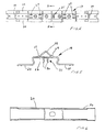
- Figure 4 is a top view of the raceway.
- Figure 5 is a cross sectional view of the crimp section taken along lines 55 of figure 4.
- Figure 6 is a top view of the raceway mounting cap.
- Figure 1 illustrates a wall system 10 formed by a series of interconnected upright prefabricated wall panels, only two substantially identical panels 11 and 12 being illustrated. Panels of different lengths can be interconnected.
- Each panel such as panels 11 and 12, include an internal rigid, rectangular frame formed by parallel top and bottom rails rigidly joined together by parallel side rails. These rails are of channel shaped configuration and open inwardly of the panel, whereby the frame confines a suitable core structure, normally a honeycomb layer or similar conventional structure.
- the core and frame are normally sandwiched between thin facing sheets disposed on opposite sides of the frame. These sheets are normally covered by a suitable fabric which define the exterior side faces of the panel.
- the panels 11 and 12 are provided with a prewired electrical assembly 13 extending longitudinally along the lower edge thereof.
- This system includes identical power blocks 14 and 15 disposed adjacent the opposite lower corners of the panel.
- the power blocks 14 and 15 are individually electrically connected by a multiconductor cable 16 or separate wire conductors.
- One of the conductors defines a ground 33.
- the cable 16 and the ground 33 extend between the power blocks 14 and 15 through an elongated, closed channel 17.
- This latter channel 17 extends between and ridgedly joins the housings of the power blocks 14 and 15 together.
- the channel 17 is in turn fixedly, but releasably, connected to the bottom rail of the frame by means of locking handles 18.
- Locator arms 29 locate the assembly 13 in lateral and longitudinal relationship with the bottom of panels 11 and 12.
- the closed channel 17 is formed by an elongated open topped raceway 19 and a cover 20 which is engageable with the raceway 19.
- the closed channel 17 is dimensioned to permit the cable 16 and ground 33 to pass therethrough.
- the raceway 19 includes a generally planar longitudinally extending bottom wall 22, and flanges 23 and 24 which extend outwardly from portions of the bottom wall 22.
- the flanges 24 and 23 define portions of the raceway 19 to which the cover 20 is attached.
- the raceway 19 is stamped and formed to define a wire crimping portion 21, numerous holes including pilot hole 28, locator arms 29, and spacers 27. As shown most clearly in FIGS. 2 and 3, the wire crimping portion 21 is stamped and formed to define a pair of crimping arms 30 which extend generally perpendicularly from the plane of the bottom wall 21 of the raceway 19.
- the raceway 19 with the power blocks 14 and 15 placed on spacers 27, cable 16 and ground 33 are initially positioned as illustrated in FIG. 3A in a fixture apparatus 40 (not shown completely in Figures 3A and 3B), which is mounted in proximity to a crimp press 35.
- the fixture apparatus 40 includes a sliding raceway mount 31 having a locating channel 36 for receiving the raceway 19 therein.
- the sliding raceway mount 31 is slidably movable along parallel rods 38 and 39 for slidable movement toward and away from the crimp press 35.
- the sliding raceway mount 31 of the fixture apparatus 40 further includes a fixed wire guide 34 extending generally perpendicularly therefrom at a location slightly spaced from the channel 36 for holding the cable 16 away from the raceway 19. Referring to FIGS.
- the assembly of the raceway 19, power blocks 14, 15, cable 16 and ground 33 is positioned such that the raceway 19 and the ground 33 are disposed between the fixed wire guide 34 and the locating channel 36 in the fixture apparatus 40.
- the cable 16 without ground 33 is disposed on the side of the fixed wire guide 34 opposite the locating channel 36.
- the raceway 19 and power blocks 14, 15 are then rotated approximately 90 degrees about the longitudinal axis of the raceway 19 such that the raceway 19 becomes positioned in the locating channel 36 of the fixture apparatus 40.
- the cable 16 will remain spaced from the ground wire 33 by the fixed wire guide 34.
- the fixture apparatus 40 further includes a wire clamp 37 mounted thereto in proximity to the pilot locator stud 42 (not shown) which engages the pilot hole 28 and the fixed wire guide 34, as shown most clearly in FIG 2.
- the clamp 37 is operative to securely engage and retain the ground 33 in a position intermediate the arms 30 of the crimping portion 21. As illustrated in FIG 2, the clamp 37 is manually engageable and releasable. However, it is to be understood that more automated clamping means may be provided.
- the clamp 37 is activated to securely retain the ground 33 between the crimp arms 30.
- the operator of the apparatus After actuation of the clamp 37, the operator of the apparatus initiates a cycle by depressing the activation buttons 32. This activation generates a slidable advancement of the fixturing apparatus 40 along the rods 38 and 39 and toward the crimp press 35.
- the proper positioning of the fixturing apparatus 40 relative to the crimp press 35 is sensed by appropriate electro-mechanical or optical sensing means incorporated into the crimp press 35.
- a crimping cycle is commenced to urge the arms 30 of the crimping portion 21 downwardly toward the bottom wall 22 of the raceway 19 and into secure crimping engagement with the ground 33.
- the fixturing apparatus 40 Upon completion of this crimping cycle, the fixturing apparatus 40 is moved away from the crimp press 35 along the rods 38 and 39 into a position where the operator of the apparatus can release the clamp 37 and urge the cable 16 into the raceway 19.
- the cover 20 is then fastened to the raceway 19 to complete the pre-wired electric subassembly 13.
- the subassembly 13 is then removed from the fixturing apparatus 33 to enable positioning of another raceway subassembly therein.
Landscapes
- Engineering & Computer Science (AREA)
- Architecture (AREA)
- Civil Engineering (AREA)
- Structural Engineering (AREA)
- Installation Of Indoor Wiring (AREA)
Applications Claiming Priority (4)
| Application Number | Priority Date | Filing Date | Title |
|---|---|---|---|
| US47889190A | 1990-02-12 | 1990-02-12 | |
| US478891 | 1990-02-12 | ||
| US563723 | 1990-08-06 | ||
| US07/563,723 US5059132A (en) | 1990-02-12 | 1990-08-06 | Electrical raceway with improved ground connection method and apparatus |
Publications (1)
| Publication Number | Publication Date |
|---|---|
| EP0442686A1 true EP0442686A1 (de) | 1991-08-21 |
Family
ID=27046040
Family Applications (1)
| Application Number | Title | Priority Date | Filing Date |
|---|---|---|---|
| EP91301088A Withdrawn EP0442686A1 (de) | 1990-02-12 | 1991-02-11 | Elektrische Sammelschiene mit Erdungsverfahren und -vorrichtung |
Country Status (3)
| Country | Link |
|---|---|
| US (1) | US5059132A (de) |
| EP (1) | EP0442686A1 (de) |
| KR (1) | KR970000131B1 (de) |
Families Citing this family (3)
| Publication number | Priority date | Publication date | Assignee | Title |
|---|---|---|---|---|
| US5349135A (en) * | 1992-06-08 | 1994-09-20 | Rosemount Office Systems, Inc. | Fastener for electrical power distribution in divider panels |
| US5975955A (en) * | 1997-12-15 | 1999-11-02 | Molex Incorporated | Shielded electrical connector assembly with grounding system |
| KR102289264B1 (ko) * | 2020-10-21 | 2021-08-11 | 이동헌 | 접지형 레이스웨이 조립체 |
Citations (5)
| Publication number | Priority date | Publication date | Assignee | Title |
|---|---|---|---|---|
| CH531240A (de) * | 1971-04-22 | 1972-11-30 | Pfisterer Elektrotech Karl | Sammelschiene für Niederspannungsverteilungsanlagen |
| DE2911100A1 (de) * | 1979-03-21 | 1980-09-25 | Bettermann Ohg Neuwalzwerk | Kabelbahn |
| DE3119194A1 (de) * | 1980-06-06 | 1982-02-04 | Aktiebolaget Konstruktions-Bakelit, Örkelljunga | Erdkontaktvorrichtung |
| US4559410A (en) * | 1984-02-28 | 1985-12-17 | Kimball International, Inc. | Access panel |
| US4740167A (en) * | 1984-03-02 | 1988-04-26 | Amp Incorporated | Power distribution unit for modular wall panels |
Family Cites Families (10)
| Publication number | Priority date | Publication date | Assignee | Title |
|---|---|---|---|---|
| US2626973A (en) * | 1949-06-28 | 1953-01-27 | Western Electric Co | Grounding terminal |
| GB972931A (en) * | 1962-02-01 | 1964-10-21 | Gen Electric Co Ltd | Improvements in or relating to sheet metal enclosures for electrical apparatus such as electric wall boxes |
| AT303864B (de) * | 1970-01-07 | 1972-12-11 | Staff & Schwarz Gmbh | Stromverteilerschiene |
| US4367370A (en) * | 1979-06-01 | 1983-01-04 | Haworth Mfg., Inc. | Power panel system with selective multiple circuits |
| US4429934A (en) * | 1979-09-27 | 1984-02-07 | Steelcase Inc. | Panel wiring system |
| GB2144928A (en) * | 1983-08-05 | 1985-03-13 | Wandsworth Electrical Limited | Switch grid |
| US4577055A (en) * | 1984-01-16 | 1986-03-18 | Harvey Hubbell Incorporated | Power pole wiring assembly |
| BR8701399A (pt) * | 1986-04-03 | 1988-01-05 | Du Pont | Tira de contacto e processo para a producao de uma fileira de conectores de grampo de borda,ou de um unico conector de grampo de borda |
| US4772228A (en) * | 1987-10-20 | 1988-09-20 | Gte Products Corporation | Electrical contact |
| US4973796A (en) * | 1989-08-10 | 1990-11-27 | Visu-Wall By Hbsa Industries, Inc. | Electrified wall structure |
-
1990
- 1990-08-06 US US07/563,723 patent/US5059132A/en not_active Expired - Lifetime
-
1991
- 1991-02-11 EP EP91301088A patent/EP0442686A1/de not_active Withdrawn
- 1991-02-11 KR KR1019910002279A patent/KR970000131B1/ko not_active Expired - Fee Related
Patent Citations (5)
| Publication number | Priority date | Publication date | Assignee | Title |
|---|---|---|---|---|
| CH531240A (de) * | 1971-04-22 | 1972-11-30 | Pfisterer Elektrotech Karl | Sammelschiene für Niederspannungsverteilungsanlagen |
| DE2911100A1 (de) * | 1979-03-21 | 1980-09-25 | Bettermann Ohg Neuwalzwerk | Kabelbahn |
| DE3119194A1 (de) * | 1980-06-06 | 1982-02-04 | Aktiebolaget Konstruktions-Bakelit, Örkelljunga | Erdkontaktvorrichtung |
| US4559410A (en) * | 1984-02-28 | 1985-12-17 | Kimball International, Inc. | Access panel |
| US4740167A (en) * | 1984-03-02 | 1988-04-26 | Amp Incorporated | Power distribution unit for modular wall panels |
Also Published As
| Publication number | Publication date |
|---|---|
| US5059132A (en) | 1991-10-22 |
| KR970000131B1 (ko) | 1997-01-04 |
| KR910016112A (ko) | 1991-09-30 |
Similar Documents
| Publication | Publication Date | Title |
|---|---|---|
| US4753005A (en) | Multiconductor electrical cable terminations and methods and apparatus for making same | |
| JP2837679B2 (ja) | ハーネス組立体及びその製造方法 | |
| EP0675567A2 (de) | Kabelraum und Verfahren zu seiner Herstellung | |
| US3848954A (en) | Clip terminal and applicator tool combination | |
| JPH02260377A (ja) | 同軸ケーブル成端方法及び装置 | |
| US4227763A (en) | Commoning connector | |
| EP0615306B1 (de) | Elektrischer Sammelverbinder | |
| US5593315A (en) | Connector readily assembled with a cable accurately positioned without using tools | |
| US4902241A (en) | Electrical interconnection system | |
| US5059132A (en) | Electrical raceway with improved ground connection method and apparatus | |
| JPH05275154A (ja) | 電気ハーネスアセンブリ | |
| JPH087968A (ja) | コネクタ及びその組立方法 | |
| US3866295A (en) | Apparatus for connecting conductors to which are back to back | |
| US4725247A (en) | Cable splicing assembly | |
| EP0369767A2 (de) | Kontakt zur Verbindung mit einem abgeschirmten Draht | |
| JPH0249671Y2 (de) | ||
| JPH01239775A (ja) | コネクター製造用の表面モールド成形された電気接点 | |
| JPS60182671A (ja) | 多重ワイヤコネクタアッセンブリ | |
| US4879810A (en) | Method for electrical wiring utilizing wire retainer | |
| JPS6151390B2 (de) | ||
| EP0643455B1 (de) | Vorrichtung zum Verdrahten eines elektrischen Verbinders | |
| JP3216789B2 (ja) | 布線配線板の製造方法および製造装置 | |
| JPS63121280A (ja) | コネクタの端子装着方法 | |
| KR940001438Y1 (ko) | 재킷 케이블용 압점 코넥터 | |
| EP0412732A1 (de) | Vorrichtung zum Herstellen eines elektrischen Kabelbaumes |
Legal Events
| Date | Code | Title | Description |
|---|---|---|---|
| PUAI | Public reference made under article 153(3) epc to a published international application that has entered the european phase |
Free format text: ORIGINAL CODE: 0009012 |
|
| AK | Designated contracting states |
Kind code of ref document: A1 Designated state(s): DE DK ES FR GB IT |
|
| STAA | Information on the status of an ep patent application or granted ep patent |
Free format text: STATUS: THE APPLICATION IS DEEMED TO BE WITHDRAWN |
|
| 18D | Application deemed to be withdrawn |
Effective date: 19920222 |