EP0442735B1 - Procédé et dispositif de revêtement objets - Google Patents
Procédé et dispositif de revêtement objets Download PDFInfo
- Publication number
- EP0442735B1 EP0442735B1 EP91301190A EP91301190A EP0442735B1 EP 0442735 B1 EP0442735 B1 EP 0442735B1 EP 91301190 A EP91301190 A EP 91301190A EP 91301190 A EP91301190 A EP 91301190A EP 0442735 B1 EP0442735 B1 EP 0442735B1
- Authority
- EP
- European Patent Office
- Prior art keywords
- containers
- coating
- coating material
- bath
- row
- Prior art date
- Legal status (The legal status is an assumption and is not a legal conclusion. Google has not performed a legal analysis and makes no representation as to the accuracy of the status listed.)
- Expired - Lifetime
Links
- 238000000576 coating method Methods 0.000 title claims abstract description 340
- 239000011248 coating agent Substances 0.000 title claims abstract description 332
- 238000000034 method Methods 0.000 title claims abstract description 55
- 239000000463 material Substances 0.000 claims abstract description 161
- 239000007788 liquid Substances 0.000 claims abstract description 43
- 239000011521 glass Substances 0.000 claims abstract description 23
- 230000007246 mechanism Effects 0.000 claims description 90
- 230000005855 radiation Effects 0.000 claims description 85
- 238000010438 heat treatment Methods 0.000 claims description 29
- 238000007598 dipping method Methods 0.000 claims description 21
- 239000000725 suspension Substances 0.000 claims description 14
- 230000032683 aging Effects 0.000 claims description 9
- 238000011144 upstream manufacturing Methods 0.000 claims description 6
- 230000015572 biosynthetic process Effects 0.000 claims description 5
- 238000005755 formation reaction Methods 0.000 claims description 5
- 239000004615 ingredient Substances 0.000 claims description 4
- 239000012141 concentrate Substances 0.000 claims description 2
- 230000001678 irradiating effect Effects 0.000 claims 2
- 241000131009 Copris Species 0.000 claims 1
- 238000004519 manufacturing process Methods 0.000 abstract description 21
- ZWEHNKRNPOVVGH-UHFFFAOYSA-N 2-Butanone Chemical compound CCC(C)=O ZWEHNKRNPOVVGH-UHFFFAOYSA-N 0.000 description 9
- 230000008569 process Effects 0.000 description 5
- 239000002904 solvent Substances 0.000 description 5
- 239000000203 mixture Substances 0.000 description 4
- 230000002411 adverse Effects 0.000 description 3
- 238000001816 cooling Methods 0.000 description 3
- 238000003618 dip coating Methods 0.000 description 3
- 238000007654 immersion Methods 0.000 description 3
- 238000010348 incorporation Methods 0.000 description 3
- 238000004806 packaging method and process Methods 0.000 description 3
- 230000000717 retained effect Effects 0.000 description 3
- 238000007789 sealing Methods 0.000 description 3
- 238000009423 ventilation Methods 0.000 description 3
- ATJFFYVFTNAWJD-UHFFFAOYSA-N Tin Chemical compound [Sn] ATJFFYVFTNAWJD-UHFFFAOYSA-N 0.000 description 2
- 230000009471 action Effects 0.000 description 2
- 238000013459 approach Methods 0.000 description 2
- 230000008901 benefit Effects 0.000 description 2
- 238000010276 construction Methods 0.000 description 2
- 230000008878 coupling Effects 0.000 description 2
- 238000010168 coupling process Methods 0.000 description 2
- 238000005859 coupling reaction Methods 0.000 description 2
- 230000003111 delayed effect Effects 0.000 description 2
- 238000000151 deposition Methods 0.000 description 2
- 230000009977 dual effect Effects 0.000 description 2
- 230000000694 effects Effects 0.000 description 2
- 230000005057 finger movement Effects 0.000 description 2
- 238000003825 pressing Methods 0.000 description 2
- 238000002203 pretreatment Methods 0.000 description 2
- 239000011253 protective coating Substances 0.000 description 2
- XOJVVFBFDXDTEG-UHFFFAOYSA-N Norphytane Natural products CC(C)CCCC(C)CCCC(C)CCCC(C)C XOJVVFBFDXDTEG-UHFFFAOYSA-N 0.000 description 1
- 238000007792 addition Methods 0.000 description 1
- 238000000137 annealing Methods 0.000 description 1
- 238000000429 assembly Methods 0.000 description 1
- 230000000712 assembly Effects 0.000 description 1
- 230000005540 biological transmission Effects 0.000 description 1
- 238000009835 boiling Methods 0.000 description 1
- 230000015556 catabolic process Effects 0.000 description 1
- 230000008859 change Effects 0.000 description 1
- 238000004140 cleaning Methods 0.000 description 1
- 238000013034 coating degradation Methods 0.000 description 1
- 238000005336 cracking Methods 0.000 description 1
- 238000006731 degradation reaction Methods 0.000 description 1
- 230000001934 delay Effects 0.000 description 1
- 238000001035 drying Methods 0.000 description 1
- 230000005670 electromagnetic radiation Effects 0.000 description 1
- 238000001704 evaporation Methods 0.000 description 1
- 230000008020 evaporation Effects 0.000 description 1
- 238000011049 filling Methods 0.000 description 1
- 239000012530 fluid Substances 0.000 description 1
- 239000012634 fragment Substances 0.000 description 1
- 239000012535 impurity Substances 0.000 description 1
- 230000010354 integration Effects 0.000 description 1
- 239000011344 liquid material Substances 0.000 description 1
- QSHDDOUJBYECFT-UHFFFAOYSA-N mercury Chemical compound [Hg] QSHDDOUJBYECFT-UHFFFAOYSA-N 0.000 description 1
- 229910052753 mercury Inorganic materials 0.000 description 1
- 229910001507 metal halide Inorganic materials 0.000 description 1
- 150000005309 metal halides Chemical class 0.000 description 1
- 238000012986 modification Methods 0.000 description 1
- 230000004048 modification Effects 0.000 description 1
- 239000002245 particle Substances 0.000 description 1
- 229920003023 plastic Polymers 0.000 description 1
- 239000004033 plastic Substances 0.000 description 1
- 229920000642 polymer Polymers 0.000 description 1
- 239000002861 polymer material Substances 0.000 description 1
- 230000002028 premature Effects 0.000 description 1
- 230000001681 protective effect Effects 0.000 description 1
- 239000013557 residual solvent Substances 0.000 description 1
- 239000011347 resin Substances 0.000 description 1
- 229920005989 resin Polymers 0.000 description 1
- 238000005507 spraying Methods 0.000 description 1
- 238000003878 thermal aging Methods 0.000 description 1
- 125000000391 vinyl group Chemical group [H]C([*])=C([H])[H] 0.000 description 1
- 229920002554 vinyl polymer Polymers 0.000 description 1
- 239000002699 waste material Substances 0.000 description 1
- XLYOFNOQVPJJNP-UHFFFAOYSA-N water Substances O XLYOFNOQVPJJNP-UHFFFAOYSA-N 0.000 description 1
Images


Classifications
-
- B—PERFORMING OPERATIONS; TRANSPORTING
- B05—SPRAYING OR ATOMISING IN GENERAL; APPLYING FLUENT MATERIALS TO SURFACES, IN GENERAL
- B05C—APPARATUS FOR APPLYING FLUENT MATERIALS TO SURFACES, IN GENERAL
- B05C3/00—Apparatus in which the work is brought into contact with a bulk quantity of liquid or other fluent material
- B05C3/02—Apparatus in which the work is brought into contact with a bulk quantity of liquid or other fluent material the work being immersed in the liquid or other fluent material
- B05C3/09—Apparatus in which the work is brought into contact with a bulk quantity of liquid or other fluent material the work being immersed in the liquid or other fluent material for treating separate articles
- B05C3/10—Apparatus in which the work is brought into contact with a bulk quantity of liquid or other fluent material the work being immersed in the liquid or other fluent material for treating separate articles the articles being moved through the liquid or other fluent material
-
- B—PERFORMING OPERATIONS; TRANSPORTING
- B05—SPRAYING OR ATOMISING IN GENERAL; APPLYING FLUENT MATERIALS TO SURFACES, IN GENERAL
- B05C—APPARATUS FOR APPLYING FLUENT MATERIALS TO SURFACES, IN GENERAL
- B05C9/00—Apparatus or plant for applying liquid or other fluent material to surfaces by means not covered by any preceding group, or in which the means of applying the liquid or other fluent material is not important
- B05C9/08—Apparatus or plant for applying liquid or other fluent material to surfaces by means not covered by any preceding group, or in which the means of applying the liquid or other fluent material is not important for applying liquid or other fluent material and performing an auxiliary operation
- B05C9/14—Apparatus or plant for applying liquid or other fluent material to surfaces by means not covered by any preceding group, or in which the means of applying the liquid or other fluent material is not important for applying liquid or other fluent material and performing an auxiliary operation the auxiliary operation involving heating or cooling
-
- Y—GENERAL TAGGING OF NEW TECHNOLOGICAL DEVELOPMENTS; GENERAL TAGGING OF CROSS-SECTIONAL TECHNOLOGIES SPANNING OVER SEVERAL SECTIONS OF THE IPC; TECHNICAL SUBJECTS COVERED BY FORMER USPC CROSS-REFERENCE ART COLLECTIONS [XRACs] AND DIGESTS
- Y10—TECHNICAL SUBJECTS COVERED BY FORMER USPC
- Y10S—TECHNICAL SUBJECTS COVERED BY FORMER USPC CROSS-REFERENCE ART COLLECTIONS [XRACs] AND DIGESTS
- Y10S118/00—Coating apparatus
- Y10S118/03—Container-related coater
Definitions
- This invention relates generally to the application of a coating to an exterior surface of fragile articles with a polymer material in order to increase their dynamical strength.
- the invention particularly concerns a method for coating exterior surfaces of rows of glass containers, comprising:
- the invention also particularly concerns an apparatus of the type for coating exterior surfaces of rows of glass containers comprising:
- Glass bottles, jars and other containers suffer commercial disadvantages from being composed of relatively fragile material.
- such containers are readily susceptible to breakage by external impact and by internal pressure of a fluid filled therein under pressure. This susceptibility is particularly evident during filling, packaging and transportation of the containers through trade channels to the end consumer, and generally requires the adoption of special procedures for careful handling of the containers to minimise breakage. Such procedures have an adverse influence on the cost of the containers and, ultimately, their contents.
- United States patent 3,200,002 relates to a method and apparatus or dipping glass articles in a heat curable liquid material. Following dipping, the containers are conveyed through a fusing oven to heat the coated articles to form a fused coating thereon. Again, this patent does not disclose the incorporation of the coating method and apparatus into a container manufacturing line immediately downstream of a lehr.
- one aspect of the present invention provides a method of the aforementioned type and characterised in that:
- the gripped containers are moved downwardly into the bath of liquid coating material against buoyancy forces applied to the containers by the coating material. Subsequently, the containers are moved upwardly out of the bath of liquid coating material.
- Moving the gripped containers out of the bath of liquid coating material preferably includes initially relatively rapidly withdrawing the containers until about two-thirds of the bottle height being coated is withdrawn from the bath of coating material. The containers are then more slowly withdrawn until they are finally withdrawn from the bath of liquid coating material.
- the coating on the containers is cured in multiple stages. That arrangement involves subjecting the coated containers to irradiation while being conveyed along the coating path in upright stable suspension so as to cure the coating on a bottom part of the containers. The containers are then repositioned on the lehr conveyor so as to be supported on the cured coating bottom part thereof. In this arrangement, the released, coated containers supported on the lehr conveyor are subsequently subjected to irradiation so as to cure the coating on a remaining part of the containers.
- the coated containers are subjected to irradiation while being conveyed along the coating path in upright stable suspension so as to cure the entire coating on the containers.
- the coating is cured in a single stage.
- Conveying the containers along the coating path is preferably continuous throughout the coating method, including during container dipping and coating setting.
- the coating path is preferably adjustable so as to vary the extent of container dipping and coating setting.
- dipping of the containers includes only partially immersing them in the bath of liquid coating material. In this way, a coating is applied to only the immersed part of the containers.
- thermal ageing of the coating can comprise or include heating the coating applied to the containers in order to remove volatile ingredients.
- heating of the coating includes subjecting the coating material to heated gas.
- the present invention provides an apparatus of the aforementioned type and characterised in that:
- the conveying means includes at least one pick-up mechanism for releasably gripping the containers at an upper region.
- the containers are held in stable suspension from the pick-up mechanism.
- the pick-up mechanism is preferably movable along a conveying path to convey the gripped containers along the coating path.
- the conveying path has a generally arcuate shaped region immediately above the coating vessel.
- the pick-up mechanism moves along the arcuate shaped region of the conveying path, containers gripped by the pick-up mechanism move downwardly into the liquid coating material and subsequently upwardly out of the material.
- the arcuate shaped region of the conveying path is preferably arranged so that, as the pick-up mechanism moves through that region moving gripped containers out of the bath of liquid coating material, the pick-up mechanism initially withdraws the containers relatively rapidly until about two-thirds of the container height being coated is withdrawn from the bath of coating material and then withdraws the containers relatively slowly until they are finally withdrawn from the material.
- the conveying path is preferably endless.
- the conveying means preferably includes an endless conveying member movable along the conveying path.
- the pick-up mechanism is preferably connected to the conveying member for movement therewith.
- the container coating is cured in a single stage or in multiple stages in alternative arrangements.
- the pick up mechanism preferably operates to release the containers after the coating on only a bottom part of each container has been cured, the pick up mechanism placing the containers on the lehr conveyor so as to be supported on the cured coating bottom part.
- the pick-up mechanism continues to grip the containers until the entire coating has been cured.
- the radiation means includes one or more radiation units.
- two or more units may operate in succession so as to each irradiate the coating applied to containers to cure the coating on a respective part of the containers.
- These radiation units may be positioned one each upstream and downstream of a release position of the containers from the pick-up mechanism.
- the upstream radiation unit preferably irradiates the coating to cure the coating on a bottom part of each container while the containers are gripped.
- the downstream radiation unit may then irradiate the coating to cure the coating on a remaining part of each container after the containers are released.
- one or more (such as two) radiation units may operate together to irradiate the entire coating applied to the containers.
- a pair of radiation units are arranged on opposite sides of the conveying path so as to direct ultraviolet light radiation across the path from opposite sides thereof toward the rows of containers.
- Heating means may be provided for at least assisting in the removal of volatile ingredients from the coating applied to the containers. Where the heating means is used in conjunction with the radiation means then preferably the heating means is located upstream of the radiation means.
- the heating means preferably includes a heating chamber connectable to a source of heated gas.
- the conveying means preferably extends through the heating chamber to move the containers therethrough and subject the applied coating to heating by the heated gas.
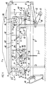
- coating apparatus 1 for dip coating bottles B in a bath of liquid coating material M so as to apply a coating C to the outer surface thereof.
- this description refers to bottles B it should be appreciated that the method and apparatus are applicable to other glass containers and articles.
- the apparatus 1 is incorporated "in-line" with a bottle manufacturing line so that bottle coating occurs as part of the bottle manufacture.
- apparatus 1 is located in the manufacturing line so that coating occurs downstream of a container lehr (not shown).
- the apparatus 1 is located adjacent a lehr conveyor R so that bottles B are taken from the conveyor R, coated and subsequently replaced on the conveyor R without interruption or disruption to the bottle manufacturing line or process generally.
- movement of the bottles B along the conveyor R from the lehr, and otherwise upstream need not be delayed for coating.
- the reference to the lehr conveyor R includes a lehr belt or a conveyor separate therefrom.
- the method and apparatus may also be used off-line for separate coating of bottles previously manufactured. Where this occurs, it is preferred that coating proceed within about 24 hours of manufacture, or at least before there is any bottle surface degradation that may adversely affect coating application. Further delays may require pre-treatment of the bottles B prior to coating. That pre-treatment may involve bottle cleaning and annealing to remove water or other impurities from the bottle surface.
- the bottles B may be presented to the apparatus 1 for coating with a bare glass outer surface.
- those bottles B may be hot-end treated so as to apply a tin coating to the outer surface, and over which the dip coating will be applied. That coating protects the glass outer surface and generally strengthens the bottles B.
- the tin coating will typically have a thickness of between 30 and 50 coating thickness units (ctu's).
- the bottles B are presented to the apparatus 1 in a controlled heated condition.
- this controlled temperature tends to improve coating, and in particular reduces the likelihood of the applied coating material M "running" on or “dripping" from the bottles B, and assists coupling between the coating material M and bottles B.
- the bottles will be at a temperature of between about 50° and 150°C, and in one particular embodiment will be at a temperature of about 100°C.
- the bottles B will exit from the lehr at a temperature of about 140°C, so that the temperature of the bottles may be controlled by bottle heating or cooling as required prior to presentation to the apparatus 1.
- the ability to use the heated condition of the bottles B as they exit from the lehr is a further advantageous reason for coating the bottles "in-line" during their manufacture.
- the bottles B are conveyed continuously along a coating path 2 in the direction of arrow A from an entry zone 3 to an exit zone 4. Those zones 3,4 are spaced apart along the lehr conveyor R. Moreover, the bottles B are conveyed in a line formation between the entry and exit zones 3,4. That line may be composed of individual bottles B arranged one behind the other (not shown). Alternatively (as shown), lateral rows of bottles B may be arranged one behind the other to form the line. The number of bottles B in the rows may vary. As shown, four (4) rows of bottles B are provided, but rows of up to about forty-eight (48) bottles B are envisaged depending on the capacity of the bottle manufacturing line.
- Conveyance of the bottles B along the coating path 2 includes collecting the bottles B at the entry zone 3 and depositing them at the exit zone 4. Collecting the bottles B includes picking them up from the lehr conveyor R, whilst depositing the bottles B includes putting them back down on the conveyor R.
- the apparatus 1 includes conveying means 5 having a conveying mechanism 6. That mechanism 6 includes an endless conveying member 7 mounted on support members 8 and movable continuously along a conveying path 9, a section 9a of which extends along the coating path 2.
- the conveying member 7 may be a conveying belt (not shown), or a pair of parallel, spaced apart chains 10 mounted on paired sets of support pulleys, wheels or sprockets 11 (as shown).
- the conveying mechanism 6 also includes a drive unit 12 for moving the conveying member 7 along the conveying path 9.
- That drive unit 12 includes a drive motor 13, such as an electric drive motor, coupled to the conveying member 7 either directly (not shown) or through a suitable belt and pulley or chain and sprocket drive transmission 14 (as shown).
- the conveying means 5 also includes at least one bottle pick-up mechanism 15 connected to the conveying member 7 for movement therewith, and operable to pick up the bottles B at the entry zone 3, carry them along the coating path 2 during coating, and put the coated bottles B down toward the exit zone 4.
- Each pick-up mechanism 15 holds the bottles B at an upper region U thereof so that they generally depend from the mechanism 15 for dipping into the bath of coating material M. That upper region U is not coated, an upper line L of coating material M being located beneath the upper region U.
- the pick-up mechanism 15 holds the bottles B adjacent the finish F thereof.
- the bottles B are held by a neck N immediately beneath the finish F. It will be appreciated that other containers and articles may be held at different upper regions U.
- a series of pick-up mechanism 15 are connected in spaced apart relation along the conveying member 7. In this way, as each mechanism 15 in turn moves through the entry zone 3, it can operate to pick-up the next in line bottle(s) at the entry zone 3. Where rows of bottles B are arranged in line, as in this embodiment, then each mechanism 15 will operate to pick up the next in line row of bottles B.
- the speed of movement of the conveying member 7 is selected so that the bottles B at the entry zone 3 are picked up by passing pick-up mechanisms 15 at a rate about equal to their rate of arrival at the entry zone 3. In this way, bottles B moving downstream from the lehr are not unduly delayed in their manufacturing process.
- the speed may be set so that the bottles B move at between about 200 and 600 bottles per minute, when arranged in lateral rows of between about 22 and 48 per row. Thus, between about 9 and 13 rows of bottles are moved along the coating path 2 per minute.
- Each pick-up mechanism 15 releasably grips each bottle B at the upper region U. That gripping is sufficient to hold the bottles B stable for dipping in the bath of coating material M.
- the mechanism 15 is capable of holding the bottles B in the coating material M against the buoyancy force applied by the material M.
- Each pick-up mechanism 15 is of any suitable construction depending on the nature of the bottles B to be gripped.
- each mechanism includes at least one pair of gripping members 16, the members 16 of each pair being relatively movable toward and away from one another between a closed position for gripping a respective bottle B and an open position not gripping that bottle B.
- Each pick-up mechanism 15 is mounted on the conveying member 7, and the conveying part section extending along the coating path 2 is configured such that, as the pick-up mechanism 15 enters the entry zone 3, the gripping members 16 are automatically orientated so as to align themselves with respective bottles B in the entry zone 3, and move about upper regions U of those bottles for gripping. Moreover, as each pick-up mechanism 15 approaches the exit zone 4, the gripping members 16 are automatically orientated so as to carefully place gripped bottles back on the lehr conveyor R.
- Adjacent pairs of gripping members 16 are spaced apart a sufficient distance so that gripped bottles B are spaced from one another.
- bottle spacing is of the order of about 40 mm.
- the gripping members 16 include gripping fingers 17. Those fingers 17 have gripping portions 18 that contact the bottles during gripping, the gripping portions 18 being composed of rigid material and contoured or otherwise shaped, or being composed of resiliently flexible material for deforming, to mate with the upper region U of the bottles B for stable gripping thereof. In this embodiment, the gripping portions 18 are shaped or deformed so as together fit neatly about a bottle neck N and provide a support shoulder 19 on which the bottle finish F bears.
- the gripping fingers 17, or at least the gripping portions 18, where rigid may be removable and replaceable for holding differently shaped containers and articles.
- the gripping fingers 17 are movable in any suitable manner.
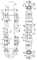
- those fingers 17 are linearly or pivotably movable toward and away from one another in alternative embodiments shown in detail in Figs. 6 to 9 and Figs. 10 to 14 of the drawings, respectively.
- each pick-up mechanism 15 includes an elongate carriage 20 mounted on the conveying member 7 and to which the gripping fingers 17 are movably connected.
- Each carriage 20 includes an elongate frame 21 connected to the conveying member 7 so as to extend transversely of the direction of movement, arrow A and a pair of support shafts 22a, 22b mounted in the frame 21 for longitudinal sliding movement relative to the frame 21.
- Individual gripping fingers 17 of each pair are fixed one each to respective shafts 22a, 22b so that sliding movement of the shafts 22a, 22b in opposite directions linearly move the fingers 17 of each pair relative to one another between their open and closed positions.
- each pick-up mechanism 15 includes an elongate carriage 23 mounted on the conveying member 7 and to which the gripping fingers 17 are movably connected.
- Each carriage 23 includes an elongated frame 24 mounted on the conveying member 7, and a respective scissor linkage 25 mounted on the frame 24.
- Each linkage 25 has at least one pair of links 26a, 26b each rigidly connected individually to one gripping finger 17 of each pair. Relative pivotal movement of the links 26a, 26b in a "scissor" action about pivot axis X causes the gripping fingers 17 to pivot relative to one another between their open and closed positions.
- Each pick-up mechanism 15 also includes drive means 27 for selectively moving the fingers 17 to their open and closed positions.
- the fingers 17 are biased into one of those positions, and movable against that bias into the other position. That bias is a resilient bias.
- the drive means 27 includes one or more biasing springs 28 for biasing the gripping fingers 17. That bias is into the closed position in these embodiments.
- Those biasing springs 28 act directly (not shown) or indirectly (as shown) on the gripping fingers 17.
- the springs 28 act on a carriage component such as between the frame 21 and support shafts 22a, 22b in the embodiment shown in drawing Figs. 6 to 9, or between the frame 25 and scissor linkages 26 in the embodiment shown in drawing Figs. 10 to 14.
- the drive means 27 also includes a drive arrangement 29 for moving the gripping fingers 17 to their open position ready for gripping bottles B at the entry zone 3 and for subsequently releasing those bottles B toward the exit zone 4.
- the drive arrangement 29 is of any suitable construction.
- the drive arrangement 29 utilizes the movement of the pick-up mechanism 15 to generate the opening movement.
- the drive arrangement 29 includes a cam and follower system 30 shown generally in Fig. 1 and in more detail in Figs. 6 and 7, and Figs. 10 and 11 of the drawings.
- the cam and follower system 30 comprises at least one cam 31, 32 fixed adjacent each of the entry and exit zones 3, 4, and at least one follower assembly 33 on each carriage 20 or 23.
- Each follower assembly 33 includes a follower element 34, which in this embodiment is a roller engageable with cams 31, 32.
- each follower element 34 automatically engages with a respectively cam 31, 32, moving the follower assembly 33 responsively in order to effect gripping finger movement against the closing bias of the biasing springs 28.
- Each follower assembly 33 acts directly (not shown) or indirectly (as shown) on the gripping fingers 17.
- each assembly 33 can act on a carriage component such as the support shafts 22a, 22b or the scissor linkages 26.
- a single follower assembly 33 may be provided in each pick-up mechanism 15 to actuate all pairs of gripping fingers 17.
- a pair of such assemblies 33 may be provided each to actuate one or more gripping finger movement, and a pair of cams 31, 32 may be fixed adjacent the entry and exit zones 3, 4, to engage with respective follower elements 34.
- the section 9a of the conveying path 9 extending along the coating path 2 is configured such that bottles B held by the pick-up mechanisms 15 move downwardly into the bath of liquid coating material M in a dipping action.
- Conveying path section 9a adjacent the baths of coating material M is of a generally arcuate shape so that as the pick-up mechanism 15 moves along the section 9a, gripped bottles B are moved into and out of the bath of coating material M.
- the bottles B move along the coating path 2 whilst in the bath.
- the coating path 2 is adjustable so that the rate of dipping into the bath of liquid coating material, the time of maximum immersion and the rate of withdrawal from the bath may be varied to obtain the coating thickness desired. Adjustment of the coating path may include adjustment of the conveying path 9, and in particular section 9a adjacent the bath of coating material M.
- the period of bottle dipping may vary according to the nature and shape of the bottles B as well as the composition of the coating material M and the coating desired. In general terms, dipping will occur for a period sufficient to apply an acceptable coating C to those bottles. In this embodiment the dipping period is of the order of about 10 seconds in order to produce a uniform coating of between about 3 and 5 microns in thickness (after curing) on the bottles, although a coating thickness of up to about 10 microns (after curing) may be applied about the heel H and across the base O of each bottle B. This added thickness assists in protecting the bottles B during subsequent use.
- the quality of coating C may be influenced by the rate at which the bottles B move into and/or out of the bath of coating material M.
- the rate of bottle vertical withdrawal from the material M can be important, with too rapid a rate of withdrawal causing an uneven coating thickness and coating drips.
- Withdrawal speed controls the thickness of the coating material M, with fast speeds dragging more material out of the bath with the bottles B, and slow speeds dragging less material out and allowing more fun-off of excess material to occur.
- the bottles B undergo a first, relatively fast withdrawal stage until about two-thirds (2/3) of the bottle height being coated is withdrawn from the bath of coating material. This is followed by a second slower withdrawal stage during which the bottles B are finally withdrawn.
- the first stage tends to avoid insufficient coating material applied on the bottles B, whilst the second stage minimizes coating material drips or runs at the base of the bottles B.
- Bottle immersion time and rate of bottle withdrawal from the bath of coating material M can be adjusted by locally varying the generally arcuate shape of path section 9a, particularly immediately adjacent the bath of coating material M. This can be achieved by selecting and changing the number and/or relative size and/or relative location of the sprockets 11 supporting spaced apart chains 10 along section 9a of conveying path 9. One or more of the sprockets 11 may be variable in this manner. By so varying the sprockets 11, the angles at which the spaced apart chains 10 move along the path section 9a, and thus move the pick up mechanisms 15 along the path section 9a, can be changed relative to the underlying bath of coating material M as desired. It will be appreciated by those skilled in this art that the sprockets 11 are movably and/or removably mounted through any suitable mounting mechanism (not shown).
- the apparatus 1 includes a vessel 35 for holding the bath of liquid coating material M.
- the vessel 35 is of any shape and size suitable for bottle dipping.
- the vessel 35 has an open top 36, a pair of side walls 37 and a pair of end walls 38.
- the side walls 37 extend transversely of the coating path 2 and converge downwardly from the open top 36 so that the end profile of the vessel 35 approximates the line of bottle movement through the bath of coating material M. This may minimize the amount of excess coating material M held in the vessel 35 during coating.
- the open top 36 may be partially closed or at least shielded to minimize ageing or curing of the coating material M therein, and thus extend bath life of that material M.
- the vessel 35 may be of a "dual tank” configuration in which an inner tank is located within an outer tank. These tanks may be of a generally similar shape, but with the open top of the inner tank located slightly below a level of the open top of the outer tank. With this configuration, the inner tank is maintained filled to overflowing with the coating material M, so that the coating material M continuously flows from the inner tank into the outer tank from which it is subsequently removed. This enables a constant level of coating material M to be maintained within the inner tank. Moreover, surface waves on the coating material M caused by movement of the bottles through the material M are minimised.
- the vessel 35 may be provided with drip and splash trays or guards for collecting any excess coating material M flowing from the dipped bottles or splashing from the vessel 35.
- the apparatus 1 may provide for heating and/or cooling of the coating material M in the vessel 35. That is achieved by mounting one or more temperature control devices 39, such as heating/cooling elements in or adjacent the vessel 35.
- temperature control devices 39 such as heating/cooling elements in or adjacent the vessel 35.
- the extent to which the coating material M is heated or cooled (if at all) by control devices 39 will depend on the nature and composition of the material M.
- the coating material M is of any suitable composition.
- suitable coating materials include the polymers as disclosed in Australian patent application 15269/88.
- the coating material M contains a methyl ethyl ketone (MEK) volatile thinning solvent. Accordingly, the bath of coating material M in the vessel 35 is maintained at a temperature below the evaportion or boiling point of the solvent. In this particular embodiment, the coating material M in the vessel 35 is maintained at an ambient temperature of up to about 30°C, whilst the bottles B are at a temperature of between about 80°C and 100°C as they enter the coating material M.
- MEK methyl ethyl ketone
- the applied coating material M is cured by subjecting the material M to electro-magnetic radiation.
- the radiation in this embodiment, is in the 0.2 to 10 micron wavelength region. In one particular embodiment, ultraviolet light radiation is used to achieve curing.
- the bottles B it may be appropriate to subject the bottles B to a single stage radiation to achieve curing.
- multi-stage irradiation of the coated bottles B is used to ensure complete and uniform curing.
- curing of at least the base O and heal H of the bottles B, through which those bottles bear on the unloading conveyor R is achieved whilst the bottles are still held by the pick-up mechanisms 15.
- the coating material M on the base O is not disturbed when the bottles B are subsequently released and placed on the conveyor R.
- Second and any subsequent stages of irradiation are conducted after the bottles B are released from the pick-up mechanisms 15, in this embodiment. This has an advantage of removing the mechanisms 15 as an obstruction to the irradiation.
- Apparatus 1 subjects the bottles B to a two stage irradiation, a first stage directing radiation upwardly toward bottles B held by the pick-up mechanism 15, and a second stage directing radiation downwardly toward the bottles B after being put down by the pick-up mechanism 15.
- the irradiation may involve reflecting the radiation about the bottles B to facilitate complete and uniform curing.
- Reflectors are used for that purpose, and they may be multifocus reflectors.
- the intensity and the period of irradiation is selected to achieve satisfactory curing, and it will be appreciated by those skilled in the relevant art that the rate of curing depends of various factors including the coating material composition and its thickness on the bottles B, as well as the amount of irradiation applied to the coating material M.
- each stage subjects passing bottles B to irradiation for a period of up to about 15 seconds, although the first stage irradiation may be for a period of only about 1 second.
- the power and wavelength band of the radiation to which the bottles B are subjected is selected so that satisfactory curing of the coating material M occurs.
- the apparatus 1 includes radiation means 40 operable to generate the energy rays.
- That radiation means 40 includes a radiation unit 41 for providing the first stage irradiation, and a radiation unit 42 for providing the second stage irradiation. These radiation units 41, 42 are rigidly mounted immediately below and above, respectively, the coating path 2.
- the radiation unit 41 directs radiation upwardly toward the bottles B to cure the coating C on the bottle base O, heel H and also partially cure the coating C on the bottle sides S, at least adjacent the base O.
- the radiation unit 42 directs radiation downwardly towards the bottles B to complete curing of the coating on the bottle sides S. Reflectors (not shown) may be included in the radiation units 41, 42 to reflect the radiation about the bottle sides S onto the coating material M.
- Each radiation unit 41, 42 includes one or more lamps 43 providing an ultravoilet light source.
- Those lamps 43 may be mercury or metal halide discharge lamps, although other lamps are envisaged.
- Ventilation may be provided by a ventilation hood 44 extending above coating path 2 and through which is drawn surrounding air passing through the radiation unit regions of the coating path 2.
- this embodiment may provide for sealing of the radiation unit regions or shielding of those regions from the coating path 2 in the region of coating material vessel 35.
- This sealing or shielding is to prevent radiation straying toward the vessel 35 and causing premature curing of bottle coatings C or curing of the coating material M within the vessel 35. This may be achieved by mounting sealing cabinets 45 about the radiation unit regions or shielding walls (not shown) between the radiation units 41, 42 and vessel 35.
- the method of the present invention further includes heating the coating material M applied to the bottles B being conveyed before that coating material M is subjected to curing.
- This initial heating step thermally ages the coating material, causing evaporation of volatile ingredients in the coating material and thereby facilitating subsequent curing of the material M.
- the coating material M includes a solvent it is important that the solvent be completely removed prior to curing, as residual solvent may adversely affect coating quality.
- the cured coating material may exhibit white markings where MEK solvent is retained during curing.
- Heating of the coating material is achieved in any suitable manner. Bottles B exiting from the coating material M will have some retained heat and this may be sufficient to age the coating material. With this arrangement, the coating path 2 would be of a length that enabled the bottles B to age during their movement from vessel 35 to radiation unit 41. That may be constructionally appropriate and economically viable depending on bottle manufacturing line constraints and requirements. Where this is possible, then the location of the apparatus at the outlet of the lehr is particularly advantageous since the heated condition of the bottles B exiting from the lehr may inherently provide a suitable bottle temperature to achieve heating of the coating material.
- heat energy is applied to the coating material M by heating means 46 to facilitate ageing.
- the heating means 46 involves applying hot gas, such as air, to the coating material M. That hot gas is supplied to a heating chamber 47 for circulation around the bottles B moving along the coating path 2 and passing through the chamber 47.
- the heating means 46 could include heater devices (not shown) mounted adjacent the coating path 2 to direct heat energy to passing bottles B.
- the heater device(s) may include infra-red heater(s).
- those heater device(s) may be used in conjunction with the hot gas drying chamber 47 applied to the coating material M.
- the period of heating is selected to achieve satisfactory ageing and, again will vary depending on several factors. In this embodiment, a period of heating of up to about 15 seconds may be used.
- the temperature of the heat energy applied to the coating material during that period is selected so that satisfactory ageing will occur within the heating period.
- the method and apparatus of the present invention may also include provision for removal of any coating material drip formations at the base O of the bottles B as they exit from vessel 35. That may be achieved by applying a jet or blast of hot gas, such as air, to the bottle bases O as they leave vessel 35 or enter heating chamber 47, the gas jet or blast separating the drips from the coating material.
- the gas jet or blast may be provided by a gas nozzle 48 mounted adjacent vessel 35 and connected to a source of hot gas.
- glass bottles B arrive at the entry zone 3 on a lehr conveyor R.
- a stacker mechanism 49 may be located adjacent the entry zone 3 so as to arrange the bottles B individually or in rows, in a sequential line, ready for pick-up.
- the conveying member 7 is continuously moving so that successive pick-up mechanisms 15 approach and pass through the entry zone 3.
- each cam and follower system 30 of the respective mechanism 15 operate, through engagement of follower elements 34 with cams 31, to move respective gripping fingers 17 from their closed position to their open position.
- the gripping fingers 17 retain that position until they over lie and extend about the neck N of respective bottles B.
- the cam and follower systems 30 then immediately operate, through disengagement of follower elements 34 from cams 31, to allow the gripping fingers 17 to return to their closed position under biasing influence of springs 28 thereby gripping the bottles B.
- the pick-up mechanism 15 and gripped bottles B are then moved by the conveying member 7 continuously along the coating path 2 toward the exit zone 4. During that movement, the bottles B are sequentially dipped in the bath of coating material M in vessel 35, exposed to heat energy in heating chamber 47 for thermal ageing, and exposed to ultraviolet light irradiation from radiation unit 41 for curing at least the base O.
- the conveying member 7 then guides the bottles B back onto the lehr conveyor R.
- the cam and follower systems 30 of the pick-up mechanism 15 again operate to move the gripping fingers 17 to their open position, thereby releasing the bottles B onto the conveyor R.
- the bottles B continue their movement along the conveyor R to the exit zone 4 and, during this movement, are exposed to radiation from radiation unit 42 for final curing of the coating material M.
- the pick-up mechanism 15 continues its movement along the conveying path 9 to return to the entry zone 3 to pick up further bottles B.
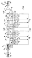
- FIG. 15 there is generally shown an alternative coating apparatus 1 for dip coating bottles B.
- This apparatus is similar to the apparatus previously described, with the same reference numerals being used to refer to the same or like components. To the extent that each apparatus 1 is the same or similar, the apparatus 1 of this embodiment will not be separately described.
- the conveying mechanism 6 again includes an endless conveying member 7 comprising a pair of spaced chains 10 mounted on paired sets of support pulleys, wheels or sprockets 11.
- One or more of the sprockets 11 located adjacent the bath of coating material M may be variable as with the previous embodiment.
- one sprocket 11 is mounted for movement between positions represented by sprockets marked 11' and 11''. This movement of that sprocket 11 will effect a change in the angle of movement of chains 10 passed vessel 35 and can be used to alter the bottle immersion time and rate of bottle movment through the bath of coating material M.
- vessel 35 is shown as a dual tank configuration, having an inner tank 50 and an outer tank 51.
- the open top 36 of the inner tank 50 is below the level of the open top 36 of the outer tank 51, so that the bath of liquid coating material M can fill to overflowing the inner tank 50. This enables the level of the coating material M to be maintained at a constant level within the inner tank 50.
- the bottles B are subjected to only a single stage irradiation to achieve curing. This irradiation occurs whilst the bottles B are held by the pick up mechanisms 15, and is provided by radiation means 40.
- Radiation means 40 comprises radiation units 52 and 53, arranged on opposite sides of the conveying path 9 so as to direct radiation toward bottles B passing therebetween.
- the radiation units 52 and 53, and bottles B are arranged relative to one another so that radiation unit 52 directs radiation upwardly at the base O and sides S of the bottles B whilst radiation unit 53 directs radiation downwardly onto the sides S of the bottles B.
- the conveying path 9, as it passes between the radiation units 52 and 53, is angled downwardly, and the radiation units 52 and 53 are angled so as to direct radiation generally across the conveying path 9.
- the radiation is applied to the bottles B as outlined above.
- Separate heating means 46 of the previous apparatus 1 is not shown in this embodiment of the apparatus, but may be provided as required. Heating of the coating material M, once applied to the bottles B, may be achieved in this embodiment by virtue of the retained heat within the bottles B.
- the apparatus 1 of this embodiment incorporates gas nozzle 48 for removing residual drips of coating material M from the bottles B.
- apparatus 1 arranges for the drips to concentrate in a constant position on each bottle B as the bottle passes the gas nozzle 48. This is achieved by tilting the bottles B suspended from the pick up mechanisms 15 so that any excess coating material M forms a drip at the lower most region of the heel H of the bottles B. That tilting may be confined to immediately adjacent the gas nozzle 48, or may extend more generally along the conveying path section 9a.
- Tilting of the bottles B may be achieved by any suitable arrangement.
- the pick up mechanisms 15 may be influenced by a tilting mechanism.
- the tilting mechanism may include a cam positioned for engagement by the pick up mechanisms 15, whereupon those mechanisms 15 move so as to tilt the bottles B.
- glass bottles B again arrive at the entry zone 3 for pick up by successive pick up mechanisms 15 to be moved continuously along the coating path 2 to exit zone 4.
- the bottles B are sequentially dipped in the bath of coating material M in vessel 35, presented to the gas nozzle 48 for removal of any material drips formed thereon, passed through heating chamber 47 for thermal aging, and exposed to ultravoilet light irradiation from radiation units 52 and 53 for curing the coating material M.
- the conveying member 7 guides the bottles B back onto the lehr conveyor R where the pick up mechanisms 15 release the bottles B.
- the method and apparatus of the present invention is particularly suitable for incorporation into a bottle manufacturing line so that no separate after-manufacture handling of the bottles is required in order to apply the coating material. Moreover, the method and apparatus can be fully automatic so that there is no increase in direct manufacturing line labor costs. As such, the cost of applying the coating material may be minimized.
- the method and apparatus of the present invention are found to be particularly effective in increasing the internal pressure and impact strength of bottles made by the blow-and-blow process as these are characterised by having very clean and strong inside surfaces.
- Bottles made by the press and blow process are subject to internal damage due to contact of the inside surface during the forming process by the pressing plunger and foreign particles. It is found that the strength of such bottles is not enhanced to the same extent by a coating applied according to the present invention. However, if a steam plunger system according to German patent Application P3920868.0 is used in the pressing process then these containers may also be substantially strengthened by a coating applied according to the present invention.
- a further advantage of incorporating the method and apparatus in the bottle manufacturing line is that the bottles are received at the entry zone for coating in a very clean condition. Such a condition facilitates application of the coating material and enhances coupling between the bottles and coating material. In contrast, off-line use of the method and apparatus may involve a treatment of the bottles prior to coating application.
- the method and apparatus of the present invention can produce a uniform coating on bottles. Moreover, the coating can be accurately applied to exterior surfaces so that interior surfaces and finishes remain coating free. This is achieved even though coating occurs on a continuous basis during bottle manufacture.
- the method and apparatus of the present invention provides for effective and economical use of the coating material.
- dipping of the bottles minimizes material waste as might occur with, for example, spraying of the material onto the bottles.
- the method and apparatus of the invention applies a coating material to individual bottles in such a way that those bottles do not touch each other, and the coating material is not disturbed such as by contact therewith, until curing of the coating material occurs. As a result, uniformity and integrity of the coating material is maintained.
Landscapes
- Coating Apparatus (AREA)
- Application Of Or Painting With Fluid Materials (AREA)
- Surface Treatment Of Glass (AREA)
- General Preparation And Processing Of Foods (AREA)
Claims (33)
- Une méthode pour le revêtement des surfaces externes de séries de récipients en verre, comprenant :(i) la saisie de chaque série de récipients (B) à la file;(ii) le transport de la série de récipients saisie le long d'un circuit de revêtement (2) en sorte que les récipients soient agencés de façon à ce qu'ils ne se touchent pas les uns les autres;(iii) l'immersion de la série de récipients transportée dans un bain d'enduit de revêtement liquide (M) pour appliquer une couche (C) de l'enduit de revêtement sur les surfaces externes des récipients;(iv) le retrait de la série de récipients enduits de la couche d'enduit de revêtement liquide;(v) le repositionnement de la série de récipients enduits; et(vi) le déblocage de la saisie de la série de récipients repositionnés et enduits;caractérisée par le fait que :(vii) chaque série de récipients en verre (B) à enduire sort d'un fourneau à verre (lehr) à une température contrôlée et sur un convoyeur de sortie de fourneau (R);(viii) chaque série de récipients (B) sur le convoyeur (R) est saisie à la file dans une zone supérieure (U) de ce dernier, et soulevée du convoyeur (R) en sorte que les récipients (B) soient suspendus en position verticale stable;(ix) le circuit de revêtement (2) le long duquel chaque série de récipients (B) est transportée est situé au-dessus du convoyeur (R);(x) chaque série de récipients (B) passe au moins partiellement dans un bain d'enduit de revêtement liquide traitable par rayons ultraviolets (M) en sorte que l'enduit soit appliqué sur les récipients;(xi) les récipients une fois enduits (B) sont vieillis à la chaleur lors de leur transport le long du circuit de revêtement (2);(xii) les récipients enduits et vieillis à la chaleur (B) sont soumis à une irradiation aux ultraviolets afin de durcir la couche (C), la couche (C) d'au moins une partie (O,H) de chaque récipient (B) étant durcie pendant le transport des récipients (B) suspendus en position verticale stable le long du circuit de revêtement (2);(xiii) chaque série de récipients (B) saisie, une fois en partie recouverte de couche durcie (C) est repositionnée sur le convoyeur (R) en aval de l'endroit où les récipients (B)ont été saisis; et,(xiv) les récipients enduits et repositionnés (B) sont relâchés pour renvoyer les récipients (B) vers le convoyeur (R).
- Une méthode ainsi revendiquée à la revendication 1, caractérisée par le fait que les récipients enduits (B) sont soumis à une irradiation pendant leur transport le long du circuit de revêtement (2) en position suspendue stable et verticale afin de durcir la couche (C) sur une partie inférieure (O,H) des récipients (B); et par le fait que les récipients enduits (B) sont repositionnés en étant placés sur le convoyeur (R) en sorte qu'ils reposent sur leur partie inférieure durcie (O,H).
- Une méthode ainsi revendiquée à la revendication 2, caractérisée par le fait que les récipients (B), une fois enduits, relâchés et maintenus sur le convoyeur (R) sont soumis à une irradiation aux rayons ultraviolets afin de traiter la couche (C) sur la partie restante (S) de ces récipients (B).
- Une méthode ainsi revendiquée à la revendication 1, caractérisée par le fait que les récipients enduits (B) sont soumis à une irradiation pendant leur transport le long du circuit de revêtement (2) en position suspendue stable et verticale afin de durcir la totalité de la couche (C) sur les récipients (B).
- Une méthode ainsi revendiquée à l'une quelconque des revendications précédentes, caractérisée par le fait que les récipients enduits (B) soumis à une irradiation sont transportés le long d'une zone à angle descendant du circuit de revêtement (2) en sorte que les séries successives de récipients (B) soient disposées l'une au-dessus de l'autre, et que l'irradiation aux ultraviolets provienne des côtés opposés de cette partie du circuit de revêtement.
- Une méthode ainsi revendiquée à l'une quelconque des revendications précédentes, caractérisée par le fait que les récipients (B) saisis sont transportés pour descendre dans le bain d'enduit de revêtement liquide (M) contre les forces de poussée appliquées aux récipients (B) par l'enduit liquide (M), et par la suite remontés verticalement pour leur sortie du bain d'enduit de revêtement liquide (M).
- Une méthode ainsi revendiquée à la revendication 6, caractérisée par le fait que les récipients (B) saisis sont retirés du bain d'enduit de revêtement liquide (M) en sorte qu'au départ on retire relativement rapidement les récipients (B) jusqu'à ce qu'environ les deux-tiers de la hauteur du récipient à enduire soient sortis du bain d'enduit de revêtement (M), et qu'ensuite on retire relativement lentement les récipients (B) jusqu'à ce que les récipients (B) soient finalement sortis du bain d'enduit de revêtement liquide (M).
- Une méthode ainsi revendiquée à la revendication 6 ou a la revendication 7, caractérisée par le fait que les récipients (B) sont transportés le long d'un circuit de revêtement (2) en forme générale d'arc pendant le mouvement d'immersion des récipients dans le bain d'enduit de revêtement liquide (M) et de sortie des récipients dudit bain liquide.
- Une méthode ainsi revendiquée à l'une quelconque des revendications précédentes, caractérisée par le fait que les récipients (B) sont en permanence transportés le long du circuit de revêtement (2) tout au long du processus de revêtement, y compris pendant l'immersion des récipients, le vieillissement et le durcissement de leur couche, et que le circuit de revêtement est réglable en sorte de pouvoir modifier la mesure du processus d'immersion des récipients et de vieillissement et de durcissement de la couche des récipients.
- Une méthode ainsi revendiquée à l'une quelconque des revendications précédentes, caractérisée par le fait que pendant l'immersion les récipients (B) ne sont que partiellement immergés dans le bain d'enduit de revêtement liquide (M) en sorte qu'une couche (C) ne soit appliquée qu'à la partie immergée des récipients (B).
- Une méthode ainsi revendiquée à l'une quelconque des revendications précédentes, caractérisée par le fait qu'après le retrait des séries de récipients (B) du bain d'enduit de revêtement liquide (M), les récipients (B) en position suspendue sont inclinés selon un angle forçant tout excès de liquide de revêtement (M) à se concentrer en un dégouttement situé sur le talon (H) des récipients (B), et que les dégouttements sont éliminés de ce talon.
- Une méthode ainsi revendiquée à la revendication 11, caractérisée par le fait que les dégouttements sont retirés des récipients (B) à l'aide d'une soufflerie à gaz.
- Une méthode ainsi revendiquée à l'une quelconque des revendications précédentes, caractérisée par le fait que la couche (C) appliquée aux récipients (B) est vieillie à la chaleur afin de supprimer les ingrédients volatils du liquide de revêtement (M).
- Une méthode ainsi revendiquée à la revendication 13, caractérisée par le fait que la couche (C) est chauffée par soumission de l'enduit de revêtement (M) à un gas chauffé.
- Une méthode ainsi revendiquée à l'une quelconque des revendications précédentes, caractérisée par le fait que les récipients (B) sont à une température d'environ 50 à 150°C avant leur immersion.
- Une méthode ainsi revendiquée à l'une quelconque des revendications précédentes, caractérisée par le fait que le bain d'enduit de revêtement liquide (M) est maintenu à une température contrôlée.
- Une méthode ainsi revendiquée à la revendication 16, caractérisée par le fait que le bain d'enduit de revêtement liquide (M) est maintenu à une température allant jusqu'à environ 30°C.
- Un appareil pour le revêtement des surfaces externes de séries de récipients en verre comprenant :(i) un bac de revêtement (35) destiné à recevoir un bain d'enduit de revêtement liquide; et(ii) des procédés de transport (5) définissant un circuit de revêtement (2) et servant à :caractérisé par le fait que:(a) saisir chaque série de récipients (B) à la file;(b) transporter les séries de récipients (B) saisies le long du circuit de revêtement en sorte que les récipients soient disposés sans se toucher les uns les autres;(c) immerger les séries de récipents transportées dans le bain d'enduit de revêtement liquide (M) pour appliquer une couche (C) du liquide de revêtement (M)sur les surfaces externes des récipients;(d) retirer les séries de récipients enduits du bain d'enduit de revêtement liquide;(e) repositionner les séries de récipients enduits; et(f) débloquer la saisie des séries de récipients enduits;(iii) chaque série de récipients en verre (B) à enduire sort d'un fourneau à verre (lehr) à une température contrôlée sur un convoyeur de sortie de fourneau (R).(iv) le bac de revêtement (35) est conçu pour accueillir un bain d'enduit de revêtement liquide traitable aux ultraviolets (M);(v) les procédés d'irradiation (40) sont fournis pour générer des rayons ultraviolets; et(vi) les procédés de transport (5) sont conçus pour : (g) saisir chaque série de récipients (B) à la file dans une partie supérieure (U) du circuit, et soulever la série de récipients saisis (B) du convoyeur (R) afin de maintenir les récipients (B) en position suspendue verticale et stable;(h) transporter les séries de récipients saisies (B) le long du circuit de revêtement (2) situé au-dessus du convoyeur (R);(i) immerger au moins partiellement les séries de récipients (B) transportées dans le bain d'enduit de revêtement liquide traitable aux ultraviolets (M) afin d'appliquer la couche (C) sur ces récipients.(j) continuer de transporter les récipients enduits (B) le long du circuit de revêtement (2) pendant que l'on procède au vieillissement par la chaleur de la couche (C).(k) transporter les récipients dont la couche (C) a été vieillie par la chaleur dans la zone d'irradiation (40)afin que les récipients enduits (B) soient soumis à une irradiation aux ultraviolets permettant de durcir la couche (C), la couche (C) d'au moins une partie (O,H) de chaque récipient B étant traitée pendant que les récipients sont transportés le long du circuit de revêtement (2) en position suspendue verticale et stable;(l) repositionner chaque série saisie de récipients (B)comportant une couche au moins partiellement traitée (C)sur le convoyeur (R) en aval de l'endroit où les récipients (B) ont été saisis; et(m) débloquer la saisie de la série de récipients enduits (B) et repositionnés pour renvoyer les récipients (B) vers le convoyeur (R).
- Un appareil ainsi spécifié à la revendication 18, caractérisé par le fait que les procédés de transport (5) comprennent au moins un mécanisme de saisie (15) pour saisir les récipients (B), de manière à ce que l'on puisse les débloquer ultérieurement, dans la zone supérieure (U) de ces procédés afin de maintenir les récipients (B) en position suspendue stable par rapport au mécanisme de saisie (15), le mécanisme de saisie (15) étant mobile le long d'un circuit de transport (9) afin de transporter les récipients saisis (B) le long du circuit de revêtement (2).
- Un appareil ainsi revendiqué à la revendication 19, caractérisé par le fait que le circuit de transport (9) comporte une zone possèdant une structure générale en forme d'arc (9a) située immédiatemment au-dessus du bac de revêtement (35) en sorte que, au fur et à mesure que le mécanisme de saisie (15) se déplace le long de la zone en forme d'arc (9a) du circuit de transport (9), les récipients (B) saisis par le mécanisme de saisie (15) descendent dans l'enduit de revêtement liquide (M) et ressortent en montant du bain d'enduit de revêtement liquide (M).
- Un appareil ainsi revendiqué à la revendication 20, caractérisé par le fait que la zone en forme d'arc (9a) du circuit de transport (9) est conçue en sorte que, lorsque le mécanisme de saisie (15) se déplace le long de cette zone (9a), sortant les récipients saisis (B) du bain d'enduit de revêtement liquide (M), le mécanisme de saisie (15) retire au départ les récipients (B) de manière relativement rapide jusqu'au retrait d' environ deux-tiers de la hauteur à enduire du bain d'enduit de revêtement liquide (M), et retire ensuite les récipients (B) de manière relativement lente jusqu'à ce que ces récipients soient entièrement sortis du bain d'enduit de revêtement liquide (M).
- Un appareil ainsi revendiqué à l'une quelconque des revendications 19 à 21, caractérisé par le fait que le circuit de transport (9) est sans fin et que les procédés de transport (5) comprennent un élément de transport sans fin (7) se déplaçant le long du circuit de transport (9), le mécanisme de saisie (15) étant relié à l'élément de transport (7) pour se déplacer avec lui.
- Un appareil ainsi revendiqué à la revendication 22, caractérisé par le fait qu'une série de mécanismes de saisie (15) sont reliés à l'élément de transport (7) dans une position espacée, chaque mécanisme de saisie (15) pouvant opérer en séquence pour saisir et déplacer des récipients successifs (B).
- Un appareil ainsi revendiqué à l'une quelconque des revendications 19 à 23, caractérisé par le fait que le mécanisme de saisie (15) opère pour relâcher les récipients (B) sur le convoyeur (R) après que seule la couche (C) recouvrant la partie inférieure (O,H) de chaque récipient (B) a été durcie, le mécanisme de saisie (15) disposant les récipients (B) sur le convoyeur (R) de manière à ce que les récipients reposent sur la partie dont la couche à été durcie (O,H).
- Un appareil ainsi revendiqué à l'une quelconque des revendications 19 à 24, caractérisé par le fait que le mécanisme de saisie (15) comporte au moins une paire d'éléments de saisie (16), les éléments de saisie (16) de chaque paire étant relativement mobiles l'un par rapport à l'autre afin de pouvoir saisir et relâcher les récipients (B).
- Un appareil ainsi revendiqué à la revendication 25, caractérisé par le fait que chaque élément de saisie (16) a un sous-élément de saisie (18), les sous-éléments de saisie (18) de chaque paire d'éléments de saisie (16) étant conçus pour saisir un récipient (B) entre eux et de manière parfaite.
- Un appareil ainsi revendiqué à la revendication 25 ou à la revendication 26, caractérisé par le fait que chaque mécanisme de saisie (15) comprend au moins un ressort de polarisation (28) destiné à polariser de manière élastique les éléments de saisie (16) de chaque paire l'un vers l'autre pour saisir les récipients (B), et un système d'entraînement (29) visant à écarter les éléments de saisie (16) l'un de l'autre contre la résilience de polarisation des ressorts de polarisation (28).
- Un appareil ainsi revendiqué à la revendication 27, caractérisé par le fait que le système d'entraînement (29) comprend au moins une came (31,32) fixée au circuit de transport (9), et au moins un galet de came (33) relié aux éléments de saisie (16) pour se déplacer avec ces derniers le long du circuit de transport (9), le galet de came (33) pouvant être couplé à chaque came (31,32) pour déplacer avec précision le galet de came (33) et écarter par là-même les éléments de saisie (16) l'un de l'autre.
- Un appareil ainsi revendiqué à l'une quelconque des revendications 18 à 28, caractérisé par le fait que les procédés d'irradiation (40) comprennent au moins deux unités d'irradiation (41,42), les unités d'irradiation pouvant opérer successivement pour irradier la couche (C) appliquée sur les récipients (B), chaque unité traitant la couche (C) d'une partie distincte (O,H,S) des récipients (B).
- Un appareil ainsi revendiqué à la revendication 29, lorsqu'elle est annexée à la revendication 24, caractérisé par le fait que les unités d'irradiation (41,42) sont positionnées l'une en amont, l'autre en aval de l'endroit de déblocage des récipients (B) par le mécanisme de saisie (15), l'unité d'irradiation située en amont (41) irradiant la couche (C) pour durcir la couche (C) de la partie inférieure (O,H) de chaque récipient saisi, l'unité d'irradiation située en aval (42) irradiant la couche (C) pour durcir la couche (C) de la partie restante (S) du récipient (B) après que ce dernier a été débloqué.
- Un appareil ainsi revendiqué à l'une quelconque des revendications 19 à 28, caractérisé par le fait que le circuit de transport (9) comporte une zone à angle descendant et adjacente aux procédés d'irradiation (40) en sorte que, lorsque le mécanisme de saisie (15) se déplace le long de cette zone à angle descendant, les séries successives de récipients (B) saisis par le mécanisme de saisie (15) sont disposées l'une au-dessus de l'autre, et que les procédés d'irradiation (40) comprennent au moins deux unités d'irradiation (52,53) disposées sur des côtés opposés de la zone à angle descendant du circuit de transport (9) afin de diffuser des rayons ultraviolets à travers le circuit de transport (9) et en direction des séries de récipients (B), rayons émanant des deux côtés opposés du circuit.
- Un appareil ainsi revendiqué à l'une quelconque des revendications 29 à 32, caractérisée par le fait que les procédés d'irradiations comportent au moins une lampe génératrice de rayons ultraviolets.
- Un appareil ainsi revendiqué à l'une quelconque des revendications 18 à 31, caractérisée par le fait que le bac de revêtement (35) est équipé d'éléments de contrôle de température (39) destinés à maintenir le bain d'enduit de revêtement liquide (14) à une température contrôlée.
Applications Claiming Priority (2)
| Application Number | Priority Date | Filing Date | Title |
|---|---|---|---|
| AU8688/90 | 1990-02-16 | ||
| AUPJ868890 | 1990-02-16 |
Publications (3)
| Publication Number | Publication Date |
|---|---|
| EP0442735A2 EP0442735A2 (fr) | 1991-08-21 |
| EP0442735A3 EP0442735A3 (en) | 1992-02-26 |
| EP0442735B1 true EP0442735B1 (fr) | 1995-08-09 |
Family
ID=3774502
Family Applications (1)
| Application Number | Title | Priority Date | Filing Date |
|---|---|---|---|
| EP91301190A Expired - Lifetime EP0442735B1 (fr) | 1990-02-16 | 1991-02-14 | Procédé et dispositif de revêtement objets |
Country Status (12)
| Country | Link |
|---|---|
| US (1) | US5211992A (fr) |
| EP (1) | EP0442735B1 (fr) |
| JP (1) | JP3112959B2 (fr) |
| AT (1) | ATE126103T1 (fr) |
| AU (1) | AU631966B2 (fr) |
| CA (1) | CA2036264C (fr) |
| CZ (1) | CZ280983B6 (fr) |
| DE (1) | DE69111845T2 (fr) |
| DK (1) | DK0442735T3 (fr) |
| ES (1) | ES2077795T3 (fr) |
| GR (1) | GR3017624T3 (fr) |
| SK (1) | SK279140B6 (fr) |
Families Citing this family (22)
| Publication number | Priority date | Publication date | Assignee | Title |
|---|---|---|---|---|
| CA2124357C (fr) * | 1991-11-25 | 2004-01-27 | Robert Gwynn Bowes | Ameliorations se rapportant a la methode et a l'appareil d'enduction d'un article |
| JP3150746B2 (ja) * | 1992-03-06 | 2001-03-26 | 大阪酸素工業株式会社 | 立体構造物の表面に樹脂被膜を形成するための装置 |
| CA2152666C (fr) * | 1993-01-25 | 2004-01-27 | Hugo Dries | Appareil prehenseur de contenants |
| DE4305081C2 (de) * | 1993-02-19 | 1996-08-01 | Minnesota Mining & Mfg | Verfahren und Vorrichtung zum Auftragen von Haftkleber auf Bogen aus Papier oder dergleichen Material |
| US5885722A (en) * | 1994-02-15 | 1999-03-23 | Minnesota Mining And Manufacturing | Method for applying coating materials to overlapped individuals sheets |
| US6517900B1 (en) * | 1994-08-17 | 2003-02-11 | 3M Innovative Properties Company | Apparatus and method for applying coating materials to individual sheet members |
| US5658619A (en) * | 1996-01-16 | 1997-08-19 | The Coca-Cola Company | Method for adhering resin to bottles |
| DE19618206A1 (de) * | 1996-05-07 | 1997-11-13 | Heye Hermann Fa | Verfahren und Vorrichtung zur Beschichtung von Glasbehältern und beschichteter Glasbehälter |
| SE9800980D0 (sv) * | 1998-03-24 | 1998-03-24 | Plm Ab | Strength testing and coating of glass containers |
| FR2832670B1 (fr) * | 2001-11-27 | 2004-09-24 | Sarl Lb De La Rosiere | Procede de decoration d'objets et dispositif pour sa mise en oeuvre |
| WO2003064304A1 (fr) * | 2002-01-29 | 2003-08-07 | Graham Packaging Company, L.P. | Procede d'application de revetements exterieurs a des contenants tridimensionnels |
| US20060172076A1 (en) * | 2002-08-30 | 2006-08-03 | Lord Corporation | Autodeposition metal dip coating process |
| ITRM20020453A1 (it) * | 2002-09-10 | 2004-03-11 | Sipa Spa | Processo e impianto di verniciatura di contenitori. |
| ITRM20020452A1 (it) * | 2002-09-10 | 2004-03-11 | Sipa Spa | Procedimento e dispositivo per il trattamento di rivestimenti |
| JP5248628B2 (ja) * | 2008-12-19 | 2013-07-31 | 東芝三菱電機産業システム株式会社 | 動力伝達装置 |
| KR101527923B1 (ko) * | 2013-05-20 | 2015-06-10 | (주) 지스트 | 침지식 코팅기 |
| CN107552327A (zh) * | 2017-07-29 | 2018-01-09 | 成都联利达五金制品有限公司 | 一种五金制品胶套浸塑装置 |
| CN107442363A (zh) * | 2017-07-29 | 2017-12-08 | 成都联利达五金制品有限公司 | 一种胶套浸塑装置 |
| CN109453955A (zh) * | 2018-07-03 | 2019-03-12 | 赵文英 | 程控行车式连续绝缘处理设备 |
| CN112974126A (zh) * | 2021-01-27 | 2021-06-18 | 南京富奥诗家具有限公司 | 一种利用油漆自动浸染的设备 |
| CN113414057B (zh) * | 2021-05-10 | 2022-09-13 | 江西省中子能源有限公司 | 一种锂电池接触片间接性分离式底涂装置 |
| CN113634456A (zh) * | 2021-08-10 | 2021-11-12 | 范亚琴 | 一种新能源汽车车壳上漆设备 |
Family Cites Families (21)
| Publication number | Priority date | Publication date | Assignee | Title |
|---|---|---|---|---|
| US1075546A (en) * | 1911-08-02 | 1913-10-14 | Frank W Burpee | Conveyer. |
| US2380968A (en) * | 1944-03-28 | 1945-08-07 | Continental Can Co | Apparatus for degreasing containers |
| US2541574A (en) * | 1946-02-15 | 1951-02-13 | Crooks Edward | Apparatus for handling glassware |
| FR1037013A (fr) * | 1951-05-11 | 1953-09-14 | Machine automatique à peindre des pièces au trempé | |
| GB782990A (en) * | 1953-11-14 | 1957-09-18 | Winkler Fallert & Co Maschf | Improvements in and relating to the varnishing and printing of hollow bodies |
| US3200002A (en) * | 1962-06-14 | 1965-08-10 | Owens Illinois Glass Co | Method and apparatus for dipping glass articles in liquid plastic |
| US3270710A (en) * | 1962-09-05 | 1966-09-06 | Owens Illinois Inc | Dip-coating machine |
| US3253943A (en) * | 1963-03-04 | 1966-05-31 | Union Carbide Corp | Bottle coating machine |
| US3734765A (en) * | 1971-10-12 | 1973-05-22 | Liberty Glass Co | Bottle coating |
| US3811921A (en) * | 1971-12-09 | 1974-05-21 | Owens Illinois Inc | Method of coating glass surface and products produced thereby |
| US4022155A (en) * | 1972-03-07 | 1977-05-10 | Dart Industries Inc. | Glassware coating apparatus |
| US3898355A (en) * | 1973-03-26 | 1975-08-05 | Ball Corp | Method for forming polymer coatings on articles |
| US3870015A (en) * | 1973-10-23 | 1975-03-11 | Anchor Hocking Corp | Method and apparatus for applying plastisol coating of uniform thickness to glass containers |
| US3914466A (en) * | 1974-01-25 | 1975-10-21 | Matsushita Electric Industrial Co Ltd | Method for coating an article |
| US4232058A (en) * | 1978-10-13 | 1980-11-04 | Gte Products Corporation | Method of coating a lamp with a U.V. curable resin with fibers therein |
| US4310566A (en) * | 1980-05-22 | 1982-01-12 | Sprague Electric Company | Batch method for terminating solid electrolyte capacitors |
| DE3033297A1 (de) * | 1980-09-04 | 1982-04-01 | Werner 7307 Aichwald Uftring | Anlage, insbesondere zum tauchlackieren oder reinigen von gegenstaenden, mit einem ein leicht verdunstendes medium enthaltenden tauchbecken und verfahren zum betreiben einer solchen anlage |
| JPS5820263A (ja) * | 1981-07-28 | 1983-02-05 | Mitsubishi Rayon Co Ltd | 合成樹脂成形品の表面硬化処理方法およびその装置 |
| US4623559A (en) * | 1985-07-12 | 1986-11-18 | Westinghouse Electric Corp. | U.V. cured flexible polyester-monoacrylate protective thermistor coatings having good edge coverage and method of coating |
| EP0462301A1 (fr) * | 1990-06-25 | 1991-12-27 | Ming-Hong Kuo | Niveleur de soudure |
| JP5828216B2 (ja) | 2010-04-23 | 2015-12-02 | 三菱レイヨン株式会社 | 水性被覆材 |
-
1991
- 1991-02-11 AU AU70941/91A patent/AU631966B2/en not_active Ceased
- 1991-02-13 CA CA002036264A patent/CA2036264C/fr not_active Expired - Fee Related
- 1991-02-14 DE DE69111845T patent/DE69111845T2/de not_active Expired - Fee Related
- 1991-02-14 US US07/656,224 patent/US5211992A/en not_active Expired - Lifetime
- 1991-02-14 ES ES91301190T patent/ES2077795T3/es not_active Expired - Lifetime
- 1991-02-14 AT AT91301190T patent/ATE126103T1/de not_active IP Right Cessation
- 1991-02-14 EP EP91301190A patent/EP0442735B1/fr not_active Expired - Lifetime
- 1991-02-14 SK SK380-91A patent/SK279140B6/sk unknown
- 1991-02-14 DK DK91301190.4T patent/DK0442735T3/da active
- 1991-02-14 CZ CS91380A patent/CZ280983B6/cs not_active IP Right Cessation
- 1991-02-15 JP JP03021848A patent/JP3112959B2/ja not_active Expired - Fee Related
-
1995
- 1995-10-04 GR GR950402737T patent/GR3017624T3/el unknown
Also Published As
| Publication number | Publication date |
|---|---|
| GR3017624T3 (en) | 1996-01-31 |
| AU7094191A (en) | 1991-08-22 |
| DE69111845D1 (de) | 1995-09-14 |
| AU631966B2 (en) | 1992-12-10 |
| ES2077795T3 (es) | 1995-12-01 |
| EP0442735A3 (en) | 1992-02-26 |
| CA2036264C (fr) | 2001-12-25 |
| JPH04219170A (ja) | 1992-08-10 |
| CA2036264A1 (fr) | 1991-08-17 |
| JP3112959B2 (ja) | 2000-11-27 |
| DK0442735T3 (da) | 1995-11-27 |
| SK279140B6 (sk) | 1998-07-08 |
| DE69111845T2 (de) | 1995-12-21 |
| EP0442735A2 (fr) | 1991-08-21 |
| US5211992A (en) | 1993-05-18 |
| CZ280983B6 (cs) | 1996-05-15 |
| CS38091A3 (en) | 1992-04-15 |
| ATE126103T1 (de) | 1995-08-15 |
Similar Documents
| Publication | Publication Date | Title |
|---|---|---|
| EP0442735B1 (fr) | Procédé et dispositif de revêtement objets | |
| CA1063888A (fr) | Transfert d'articles prechauffes sur un transporteur de refroidissement avant leur revetement a la poudre | |
| US5326258A (en) | Method and apparatus for heating preform blanks composed of partly crystalline synthetic resins produced by injection molding | |
| JP2010525295A (ja) | 容器のコーティングを乾燥および硬化させるための方法および装置、ならびにそれらから製造される容器 | |
| US3734765A (en) | Bottle coating | |
| WO1990005031A1 (fr) | Systeme de revetement transparent d'un recipient en verre | |
| US3060057A (en) | Method and apparatus for controlling distribution of plastic coatings on articles | |
| JP2006502838A (ja) | 熱可塑性樹脂容器のコーティングを処理するための方法および装置 | |
| US3270710A (en) | Dip-coating machine | |
| JPH0657616B2 (ja) | 表面処理ガラス容器の製造方法及び装置 | |
| AU660509B2 (en) | Improvements in or relating to article coating method and apparatus | |
| US3200002A (en) | Method and apparatus for dipping glass articles in liquid plastic | |
| US5458682A (en) | Glass container coating apparatus with staggered rows of coating rollers | |
| US3615327A (en) | Methods and apparatus for applying oxide coating to glass containers | |
| US4009298A (en) | Method of curing plastic coatings on bottles | |
| US20060127616A1 (en) | Controlled infrared/fluid coating cure process | |
| NO134370B (fr) | ||
| GB2145963A (en) | Apparatus for heat-shrinking thermoplastic sleeves about containers | |
| US4478781A (en) | Method and apparatus for refurbishment of plastic containers | |
| GB1565679A (en) | Bottle holding chuck | |
| JPS6323764A (ja) | 容器を塗装し硬化させる方法およびその装置 |
Legal Events
| Date | Code | Title | Description |
|---|---|---|---|
| PUAI | Public reference made under article 153(3) epc to a published international application that has entered the european phase |
Free format text: ORIGINAL CODE: 0009012 |
|
| AK | Designated contracting states |
Kind code of ref document: A2 Designated state(s): AT BE CH DE DK ES FR GB GR IT LI LU NL SE |
|
| PUAL | Search report despatched |
Free format text: ORIGINAL CODE: 0009013 |
|
| AK | Designated contracting states |
Kind code of ref document: A3 Designated state(s): AT BE CH DE DK ES FR GB GR IT LI LU NL SE |
|
| 17P | Request for examination filed |
Effective date: 19920817 |
|
| 17Q | First examination report despatched |
Effective date: 19940330 |
|
| GRAA | (expected) grant |
Free format text: ORIGINAL CODE: 0009210 |
|
| AK | Designated contracting states |
Kind code of ref document: B1 Designated state(s): AT BE CH DE DK ES FR GB GR IT LI LU NL SE |
|
| ITF | It: translation for a ep patent filed | ||
| REF | Corresponds to: |
Ref document number: 126103 Country of ref document: AT Date of ref document: 19950815 Kind code of ref document: T |
|
| REF | Corresponds to: |
Ref document number: 69111845 Country of ref document: DE Date of ref document: 19950914 |
|
| RAP2 | Party data changed (patent owner data changed or rights of a patent transferred) |
Owner name: INTERNATIONAL PARTNERS IN GLASS RESEARCH |
|
| ET | Fr: translation filed | ||
| NLT2 | Nl: modifications (of names), taken from the european patent patent bulletin |
Owner name: INTERNATIONAL PARTNERS IN GLASS RESEARCH |
|
| REG | Reference to a national code |
Ref country code: DK Ref legal event code: T3 |
|
| REG | Reference to a national code |
Ref country code: ES Ref legal event code: FG2A Ref document number: 2077795 Country of ref document: ES Kind code of ref document: T3 |
|
| REG | Reference to a national code |
Ref country code: GR Ref legal event code: FG4A Free format text: 3017624 |
|
| PLBE | No opposition filed within time limit |
Free format text: ORIGINAL CODE: 0009261 |
|
| STAA | Information on the status of an ep patent application or granted ep patent |
Free format text: STATUS: NO OPPOSITION FILED WITHIN TIME LIMIT |
|
| 26N | No opposition filed | ||
| PGFP | Annual fee paid to national office [announced via postgrant information from national office to epo] |
Ref country code: GR Payment date: 20000119 Year of fee payment: 10 |
|
| PGFP | Annual fee paid to national office [announced via postgrant information from national office to epo] |
Ref country code: DK Payment date: 20000124 Year of fee payment: 10 |
|
| PGFP | Annual fee paid to national office [announced via postgrant information from national office to epo] |
Ref country code: BE Payment date: 20000125 Year of fee payment: 10 |
|
| PGFP | Annual fee paid to national office [announced via postgrant information from national office to epo] |
Ref country code: SE Payment date: 20000127 Year of fee payment: 10 Ref country code: LU Payment date: 20000127 Year of fee payment: 10 |
|
| PGFP | Annual fee paid to national office [announced via postgrant information from national office to epo] |
Ref country code: CH Payment date: 20000224 Year of fee payment: 10 |
|
| PGFP | Annual fee paid to national office [announced via postgrant information from national office to epo] |
Ref country code: AT Payment date: 20000225 Year of fee payment: 10 |
|
| PGFP | Annual fee paid to national office [announced via postgrant information from national office to epo] |
Ref country code: NL Payment date: 20000229 Year of fee payment: 10 |
|
| PG25 | Lapsed in a contracting state [announced via postgrant information from national office to epo] |
Ref country code: LU Free format text: LAPSE BECAUSE OF NON-PAYMENT OF DUE FEES Effective date: 20010214 Ref country code: DK Free format text: LAPSE BECAUSE OF NON-PAYMENT OF DUE FEES Effective date: 20010214 Ref country code: AT Free format text: LAPSE BECAUSE OF NON-PAYMENT OF DUE FEES Effective date: 20010214 |
|
| PG25 | Lapsed in a contracting state [announced via postgrant information from national office to epo] |
Ref country code: SE Free format text: LAPSE BECAUSE OF NON-PAYMENT OF DUE FEES Effective date: 20010215 |
|
| PG25 | Lapsed in a contracting state [announced via postgrant information from national office to epo] |
Ref country code: LI Free format text: LAPSE BECAUSE OF NON-PAYMENT OF DUE FEES Effective date: 20010228 Ref country code: GR Free format text: LAPSE BECAUSE OF NON-PAYMENT OF DUE FEES Effective date: 20010228 Ref country code: CH Free format text: LAPSE BECAUSE OF NON-PAYMENT OF DUE FEES Effective date: 20010228 Ref country code: BE Free format text: LAPSE BECAUSE OF NON-PAYMENT OF DUE FEES Effective date: 20010228 |
|
| BERE | Be: lapsed |
Owner name: INTERNATIONAL PARTNERS IN GLASS RESEARCH Effective date: 20010228 |
|
| PG25 | Lapsed in a contracting state [announced via postgrant information from national office to epo] |
Ref country code: NL Free format text: LAPSE BECAUSE OF NON-PAYMENT OF DUE FEES Effective date: 20010901 |
|
| REG | Reference to a national code |
Ref country code: CH Ref legal event code: PL |
|
| EUG | Se: european patent has lapsed |
Ref document number: 91301190.4 |
|
| REG | Reference to a national code |
Ref country code: DK Ref legal event code: EBP |
|
| NLV4 | Nl: lapsed or anulled due to non-payment of the annual fee |
Effective date: 20010901 |
|
| REG | Reference to a national code |
Ref country code: GB Ref legal event code: IF02 |
|
| PGFP | Annual fee paid to national office [announced via postgrant information from national office to epo] |
Ref country code: GB Payment date: 20041116 Year of fee payment: 15 |
|
| PGFP | Annual fee paid to national office [announced via postgrant information from national office to epo] |
Ref country code: ES Payment date: 20041201 Year of fee payment: 15 |
|
| PGFP | Annual fee paid to national office [announced via postgrant information from national office to epo] |
Ref country code: FR Payment date: 20050211 Year of fee payment: 15 |
|
| PGFP | Annual fee paid to national office [announced via postgrant information from national office to epo] |
Ref country code: DE Payment date: 20050223 Year of fee payment: 15 |
|
| PG25 | Lapsed in a contracting state [announced via postgrant information from national office to epo] |
Ref country code: GB Free format text: LAPSE BECAUSE OF NON-PAYMENT OF DUE FEES Effective date: 20060214 |
|
| PG25 | Lapsed in a contracting state [announced via postgrant information from national office to epo] |
Ref country code: ES Free format text: LAPSE BECAUSE OF NON-PAYMENT OF DUE FEES Effective date: 20060215 |
|
| PGFP | Annual fee paid to national office [announced via postgrant information from national office to epo] |
Ref country code: IT Payment date: 20060228 Year of fee payment: 16 |
|
| PG25 | Lapsed in a contracting state [announced via postgrant information from national office to epo] |
Ref country code: DE Free format text: LAPSE BECAUSE OF NON-PAYMENT OF DUE FEES Effective date: 20060901 |
|
| GBPC | Gb: european patent ceased through non-payment of renewal fee |
Effective date: 20060214 |
|
| REG | Reference to a national code |
Ref country code: FR Ref legal event code: ST Effective date: 20061031 |
|
| REG | Reference to a national code |
Ref country code: ES Ref legal event code: FD2A Effective date: 20060215 |
|
| PG25 | Lapsed in a contracting state [announced via postgrant information from national office to epo] |
Ref country code: FR Free format text: LAPSE BECAUSE OF NON-PAYMENT OF DUE FEES Effective date: 20060228 |
|
| PG25 | Lapsed in a contracting state [announced via postgrant information from national office to epo] |
Ref country code: IT Free format text: LAPSE BECAUSE OF NON-PAYMENT OF DUE FEES Effective date: 20070214 |