EP0442767A1 - Verfahren und Vorrichtung zum Behandeln eines natürlichen Gases - Google Patents
Verfahren und Vorrichtung zum Behandeln eines natürlichen Gases Download PDFInfo
- Publication number
- EP0442767A1 EP0442767A1 EP91400092A EP91400092A EP0442767A1 EP 0442767 A1 EP0442767 A1 EP 0442767A1 EP 91400092 A EP91400092 A EP 91400092A EP 91400092 A EP91400092 A EP 91400092A EP 0442767 A1 EP0442767 A1 EP 0442767A1
- Authority
- EP
- European Patent Office
- Prior art keywords
- gas
- additive
- phase
- water
- aqueous phase
- Prior art date
- Legal status (The legal status is an assumption and is not a legal conclusion. Google has not performed a legal analysis and makes no representation as to the accuracy of the status listed.)
- Granted
Links
Images
Classifications
-
- F—MECHANICAL ENGINEERING; LIGHTING; HEATING; WEAPONS; BLASTING
- F17—STORING OR DISTRIBUTING GASES OR LIQUIDS
- F17D—PIPE-LINE SYSTEMS; PIPE-LINES
- F17D1/00—Pipe-line systems
- F17D1/02—Pipe-line systems for gases or vapours
- F17D1/04—Pipe-line systems for gases or vapours for distribution of gas
- F17D1/05—Preventing freezing
-
- E—FIXED CONSTRUCTIONS
- E21—EARTH OR ROCK DRILLING; MINING
- E21B—EARTH OR ROCK DRILLING; OBTAINING OIL, GAS, WATER, SOLUBLE OR MELTABLE MATERIALS OR A SLURRY OF MINERALS FROM WELLS
- E21B43/00—Methods or apparatus for obtaining oil, gas, water, soluble or meltable materials or a slurry of minerals from wells
- E21B43/34—Arrangements for separating materials produced by the well
-
- F—MECHANICAL ENGINEERING; LIGHTING; HEATING; WEAPONS; BLASTING
- F17—STORING OR DISTRIBUTING GASES OR LIQUIDS
- F17D—PIPE-LINE SYSTEMS; PIPE-LINES
- F17D1/00—Pipe-line systems
- F17D1/005—Pipe-line systems for a two-phase gas-liquid flow
Definitions
- the present invention relates to a method and a device for implementing and regenerating corrosion inhibiting additives and / or hydrates for transporting and treating a natural gas.
- the natural gas is saturated with water at the temperature of production; during transport, the gas generally undergoes a temperature drop which causes a condensation of part of the water, but which can also under certain conditions cause the formation of hydrate crystals, which are inclusion compounds hydrocarbon molecules in crystal structures formed by water molecules and which form at a temperature significantly above 0 ° C.
- hydrate crystals which are inclusion compounds hydrocarbon molecules in crystal structures formed by water molecules and which form at a temperature significantly above 0 ° C.
- the formation of hydrates in a gas pipeline can lead to plugging and stopping production. To avoid this, it is necessary either to dehydrate the gas before transporting it, or to inject a hydrate inhibitor such as methanol or ethylene glycol into the gas.
- the gas is generally treated in a washing unit with glycol to adjust the water dew point to the value imposed for transport, the latter being carried out under single-phase conditions; in the second case, the inhibitor is introduced into the gas just after the wellhead and the transport is carried out at least partially under two-phase conditions.
- the gas which can come from several different wells collected on the same pipeline, is generally dehydrated to obtain a lower water dew point than that required by transport; this second dehydration step can be carried out in most cases either by absorption of water in glycol, or by adsorption of water on molecular sieves; the dehydration process thus implemented may be different from that used on the production site to ensure the water dew point necessary for transport.
- This second dehydration step is essential if we want to be able to cool the gas to a relatively low temperature, which can for example be between -10 and -40 ° C, in order to extract the liquids from natural gas, that is to say the hydrocarbons other than methane which can be delivered liquid at room temperature. Under these conditions, the additives which have been injected for transport (hydrate formation inhibitors and corrosion inhibitors) are absorbed during the treatment and are not recycled.
- the method according to the invention corresponds to a new implementation of these anti-hydrate and / or anti-corrosion additives which allows their recycling.
- normally liquid liquid under normal conditions of temperature and pressure.
- the proportion by weight of anti-hydrate solvent in water is generally from 10 to 70% and preferably from 20 to 50%.
- the anti-hydrate additive and the water at least one anti-corrosion additive, non-hydrocarbon at least partially miscible with water or dispersible in the water and preferably vaporizing at a boiling temperature lower than that of water or forming with water an azeotrope whose boiling point is lower than that of water, so that it can be entrained by the gas during step (a) of the process.
- the proportion of aqueous liquid phase introduced into the contact zone generally corresponds to 0.05 to 5% by weight of the mass flow rate of gas to be treated and advantageously from 0.1 to 1%, the contacting step s generally performing at a temperature and at a pressure corresponding substantially to that of the gases leaving the production well, for example approximately at 20 to 100 ° C. under 0.1 to 25 MPa.
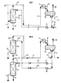
- FIG. 1 The principle of the process according to the invention is illustrated by the diagram in FIG. 1, applied by way of example to a natural gas containing methane, associated higher hydrocarbons, acid gases (carbon dioxide, hydrogen sulfide) and saturated in water under production temperature and pressure conditions.
- the natural gas leaving the production well head arrives via the pipe 1, at the bottom of a contacting enclosure G1 preferably substantially vertical. It is brought into contact, in the contact zone G1 preferably operating against the current, with a mixture consisting of water, at least one hydrate-inhibiting solvent alone or in admixture with at least one corrosion-inhibiting additive and coming from line 4.
- a gas phase laden with solvent and additive is removed at the head via line 3.
- an aqueous phase substantially free of solvent and additive is drawn off via line 2.
- the overhead gas phase is transported in line 3 over a distance which may be several kilometers and arrives via line 5 at the reception terminal where the gas can be treated before it is dispatched into the commercial network.
- the gas flowing in line 5 is cooled to the low temperature necessary for treatment in the heat exchanger E1 by a refrigerant external to the process, which causes partial condensation; this cooling does not cause a hydrate formation phenomenon due to the presence of the inhibiting solvent in the gas in a sufficiently large amount.
- the cooled mixture leaving the exchanger E1 via line 6 consists of a condensate comprising an aqueous liquid phase which contains most of the water, solvent and additive which were in the gas leaving the contact zone G1 via the conduit 3, and of a so-called poor gas phase depleted in heavy hydrocarbons.
- the phenomena of hydrate formation and corrosion do not occur, because they are inhibited by the presence of the anti-hydrate solvent and the anti-corrosion additive which protect the whole of the installation.
- One of the advantages of the process according to the invention is that the anti-hydrate and anti-corrosion additives which are used are effective over the entire installation, that is to say the contact zone G1 between the gas and additives on the production site, the transport pipe which allows the gas to be transported from the production zone to the reception terminal and the treatment zone during which natural gas is separated from water and hydrocarbons the heavier.
- part of the gas to be transported (line 12) can be directly mixed with the gas leaving the contact area G1 through line 3, without having to pass through the contact area G1.
- natural gas is generally produced by several wells. In this case it is possible to collect the effluents from several different wells on a single process according to the invention; for this, the gas coming from certain wells can be introduced into the process according to the invention by the pipe 1, while the gas coming from the other wells can be introduced into the process through the pipe 12.
- natural gas is produced by two main sites and it is assumed to contain methane, associated higher hydrocarbons and to be saturated with water under the conditions of temperature and pressure of production.
- the outgoing natural gas of a production wellhead is treated as described above for FIG. 1.
- the natural gas leaving another production wellhead arrives via the conduit 21. It is brought into contact, in the contact zone G2, with a mixture consisting of water and hydrate-inhibiting solvent coming from line 24.
- a gas phase laden with solvent is removed at the head, through line 23.
- an aqueous phase substantially free of solvent is drawn off via line 22.
- the overhead gas phase is transported in line 23 and it is mixed in line 25 with gas coming from the first production site and circulating in line 3.
- All of the gas is transported over a distance which can be several kilometers and arrives via line 5 at the reception terminal where the gas can be treated before it is sent to the commercial network.
- the gas flowing in line 5 is cooled to the low temperature necessary for treatment in the heat exchanger E1 by a refrigerant external to the process, which causes partial condensation; this cooling does not cause a hydrate formation phenomenon due to the presence of the inhibiting solvent in the gas in a sufficiently large amount.
- the cooled mixture leaving the exchanger E1 via the conduit 6 consists of an aqueous liquid phase which contains most of the water and the solvent which were on the one hand in the gas leaving the contact zone G1 through line 3 and on the other hand in the gas leaving the contact zone G2 through line 23, of a liquid hydrocarbon phase consisting of the heaviest hydrocarbons in the gas and of a so-called lean poor gas phase heavy hydrocarbons.
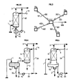
- FIG 3 is shown an example of production scheme operating with four wells distant from each other denoted respectively PS1, PS2, PS3 and PS4.
- the gas is conveyed via lines 100 from the well PS1, 200 from the well PS2, 300 from the well PS3, 400 from the well PS4 to a central processing platform PTC.
- the gas is cooled so as to obtain an aqueous phase and a partially dehydrated gas, the water dew point of which complies with the transport specification which imposes a value, for example less than or equal to -10 ° C.
- the gas thus obtained is compressed by a compressor placed on the PTC platform and evacuated via line 500.
- the aqueous phase is returned to the production wells PS1, PS2, PS3 and PS4 by the pumps which return, via the pipes 101, 201, 301 and 401, the flow rates of the aqueous phase proportional to the flow rates of gas conveyed by the pipes 100, 200, 300 and 400.
- a contactor which makes it possible to charge the product gas with an additive and to evacuate an aqueous phase substantially free of the additive which it contained at the start.
- an additive reserve which is renewed periodically, enables regular add-ons to compensate for the loss of additive.
- natural gas is produced accompanied by hydrocarbon condensates, that is to say that the effluent leaving the well consists of a gaseous phase and a fraction of liquids, composed of hydrocarbons. the heaviest; in most cases, an aqueous liquid phase is also present at the outlet of the well.
- the diagram of the process according to the invention may be slightly different to take into account the liquid hydrocarbon phase; this variant is illustrated by the Figure 4: the condensate gas leaving the production wellhead arrives via line 1 and enters the upper part of a separator flask B2 in which the 3 phases are separated: the aqueous phase, consisting of water deposit, is withdrawn through the conduit 30; the liquid hydrocarbon phase is drawn off through line 32, taken up by pump P3 and discharged through line 33; the gaseous phase is drawn off via line 31 and brought into contact, in contact zone G1, with a mixture consisting of water, solvent and additives and coming from line 4.
- the condensate gas leaving the production wellhead arrives via line 1 and enters the upper part of a separator flask B2 in which the 3 phases are separated: the aqueous phase, consisting of water deposit, is withdrawn through the conduit 30; the liquid hydrocarbon phase is drawn off through line 32, taken up by pump P3 and discharged through line 33; the gaseous phase is drawn off via line 31
- FIG. 5 A variant of the case of condensate gas production is illustrated in FIG. 5: in this case, the separating flask B2 and the contact area G1 are integrated into a single item of equipment in order to gain compactness, a criterion which is particularly interesting in the case of production at sea.
- the condensate gas leaving the production wellhead arrives via line 1 and enters the separator flask B2 in which are separated the liquid hydrocarbon phase, an aqueous phase consisting of reservoir water and water from the contact zone G1 in direct relation with the upper part of the separator B2 and a gas phase which is brought into contact against the current, in the contact zone G1, with a mixture consisting of water, solvent and additives and coming from line 4.
- a gas phase laden with solvent and additives is discharged at the head, via line 3, which is transported to the reception terminal.
- the aqueous phase substantially free of solvent and additives is mixed with the aqueous phase of deposit water, decanted and drawn off through line 2.
- the liquid hydrocarbon phase is drawn off from the flask B2 through line 32, taken up by pump P3 and evacuated through line 33; this phase can either be transported by an independent pipe to a reception terminal, or mixed with the gas circulating in the pipe 3, in which case the transport under these conditions is carried out in two-phase regime.
- This variant allows the packing G1 to play a dual role: on the one hand it makes it possible to make contact between the aqueous phase arriving via line 4 and the gas arriving through line 1; on the other hand it makes it possible to stop the liquid droplets entrained by the gas and thus to improve the separation between phases.
- the installation shown diagrammatically in FIG. 5 can be carried out on land, on a platform at sea, or under the sea.
- the gas does not contain hydrocarbon condensate at the outlet of the well
- the water discharged through line 2 can be sent directly to the sea provided that the additive has been sufficiently purified in the contact column G1.
- the gas is then transported by an underwater pipe in single-phase conditions.
- the gas contains a hydrocarbon condensate at the outlet of the well, after separation, this condensate is preferably remixed with the gas so as to carry out simultaneous transport under two-phase conditions which makes it possible to transport the two phases in a single pipe. It may be necessary to raise the pressure level before transport, which can be done either after mixing by a two-phase pump or compressor, or after mixing by passing the gas through a compressor and the condensate through a pump.
- the anti-hydrate solvent can advantageously be, for example, methanol. It can also be chosen, for example, from the following solvents: methylpropylether, ethylpropylether, dipropylether, methyltertiobutylether, dimethoxymethane, dimethoxyethane, ethanol, methoxyethanol, propanol, used alone or as a mixture.
- the anti-corrosion additive may preferably be chosen from organic compounds of the chemical family of amines, such as diethylamine, propylamine, butylamine, triethylamine, dipropylamine, ethylpropylamine, ethanolamine, cyclohexylamine, pyrridic morpholine, ethylenediamine, used alone or as a mixture.
- organic compounds of the chemical family of amines such as diethylamine, propylamine, butylamine, triethylamine, dipropylamine, ethylpropylamine, ethanolamine, cyclohexylamine, pyrridic morpholine, ethylenediamine, used alone or as a mixture.
- the corrosion inhibitor additive is dispersible in water and if its boiling temperature is higher than that of water, said additive can be recovered and recycled as shown in the diagram in FIG. 2A: according to this diagram, the natural gas leaving the production wellhead arrives via the pipe 1. It is brought into contact, in the contact zone G1, with a mixture consisting of water, hydrate inhibiting solvent and d corrosive inhibiting additive coming from line 4. A gas phase containing essentially solvent is removed at the head via line 3.
- the aqueous phase substantially freed of solvent, but still containing the majority of the corrosion-inhibiting additive which has not been entrained by the gas leaves the contact zone G1 via the conduit 2, and enters the separator S1 in which the water is separated from the corrosion inhibiting additive; the water, practically completely free of solvent and of corrosion-inhibiting additive, leaves S1 through line 40; the corrosion inhibitor additive leaves S1 through line 41, is taken up by pump P4 and sent via line 42 into line 3 in order to be remixed with the gas coming from contact zone G1 and circulating in line 3 to inhibit corrosion during gas transport to the processing terminal.
- the separator S1 can be of different types such as for example coalescer, decanter, extractor, distiller, centrifuge.
- the refrigeration temperature required to extract the heaviest hydrocarbons from the gas is a function of the gas pressure and the desired recovery rate; she may be for example between +10 and -60 ° C and preferably between -10 and -40 ° C for a gas pressure of for example between 0.1 and 25 MPa and preferably between 0.2 and 10 MPa.
- This refrigeration can be provided either by an external refrigeration cycle, or by other means such as for example the expansion of the gas in a turbine or an expansion valve.
- the dehydrated gas leaving the cooling step (c) can be subjected to an additional treatment.
- the solvent leaving this washing zone can then be regenerated by lowering the pressure and / or heating and recycled.
- the at least partially dehydrated and deacidified gas is withdrawn.
- the contact zone used during step (a) can be produced by means of a column of plates or of a column with packing.
- Different packings can be used, in particular so-called “structured” packings which are arranged regularly in the contact zone. It is also possible to use packings formed of metallic fabrics assembled in the form of cylindrical pads of a diameter equal to the internal diameter of the contact column.
- any other device known to a person skilled in the art making it possible to make such contact between the liquid phase and the gas phase can also be used.
- a device can for example be constituted by a centrifugal contactor in which the counter-current flow of the two phases takes place under the effect no longer of gravity but under the effect of a centrifugal force, with a view to make a device contact of a reduced volume.
- a natural gas is produced on a site, it enters the process according to the invention through line 1. Its pressure is 7.5 MPa (abs) and its temperature is 40 ° C; its composition is given in table 1 and it is saturated with water. Its flow rate is 123 tonnes / h, which corresponds to 3.5 MNm3 / day.
- the head gas phase is transported in line 3 which is an underwater pipeline 0.25 m in diameter over a distance of 11.2 km and arrives via line 5 at the reception terminal where its pressure is 6.95 Mpa due to the pressure drop in the pipeline.
- the gas is cooled to a temperature of -15 ° C in the heat exchanger E1 by a refrigerant external to the process; this cooling causes partial condensation of the gas.
- the cooled mixture leaving the exchanger E1 via line 6 consists of the non-condensed gas and, on the one hand, 226 kg / h of an aqueous liquid phase of a mixture of water, methanol and triethylamine, d on the other hand 410 kg / h of a liquid hydrocarbon phase.
Landscapes
- Engineering & Computer Science (AREA)
- Mechanical Engineering (AREA)
- General Engineering & Computer Science (AREA)
- Mining & Mineral Resources (AREA)
- Life Sciences & Earth Sciences (AREA)
- Geology (AREA)
- Fluid Mechanics (AREA)
- Environmental & Geological Engineering (AREA)
- Physics & Mathematics (AREA)
- General Life Sciences & Earth Sciences (AREA)
- Geochemistry & Mineralogy (AREA)
- Organic Low-Molecular-Weight Compounds And Preparation Thereof (AREA)
- Pipeline Systems (AREA)
- Devices And Processes Conducted In The Presence Of Fluids And Solid Particles (AREA)
- Separation By Low-Temperature Treatments (AREA)
Applications Claiming Priority (2)
| Application Number | Priority Date | Filing Date | Title |
|---|---|---|---|
| FR9000757 | 1990-01-23 | ||
| FR9000757A FR2657416B1 (fr) | 1990-01-23 | 1990-01-23 | Procede et dispositif pour le transport et le traitement d'un gaz naturel. |
Publications (2)
| Publication Number | Publication Date |
|---|---|
| EP0442767A1 true EP0442767A1 (de) | 1991-08-21 |
| EP0442767B1 EP0442767B1 (de) | 1994-07-20 |
Family
ID=9393030
Family Applications (1)
| Application Number | Title | Priority Date | Filing Date |
|---|---|---|---|
| EP91400092A Expired - Lifetime EP0442767B1 (de) | 1990-01-23 | 1991-01-16 | Verfahren und Vorrichtung zum Behandeln eines natürlichen Gases |
Country Status (9)
| Country | Link |
|---|---|
| US (1) | US5127231A (de) |
| EP (1) | EP0442767B1 (de) |
| JP (1) | JP3074394B2 (de) |
| AU (1) | AU640988B2 (de) |
| CA (1) | CA2034806C (de) |
| DE (1) | DE69102899T2 (de) |
| FR (1) | FR2657416B1 (de) |
| MY (1) | MY106171A (de) |
| NO (1) | NO176534C (de) |
Cited By (5)
| Publication number | Priority date | Publication date | Assignee | Title |
|---|---|---|---|---|
| WO1994024413A1 (en) * | 1993-04-08 | 1994-10-27 | Bp Chemicals Limited | Method for inhibiting solids formation and blends for use therein |
| FR2735210A1 (fr) * | 1995-06-06 | 1996-12-13 | Inst Francais Du Petrole | Procede de recyclage d'un additif dispersant utilise pour le transport d'un gaz a condensat ou d'un petrole avec gaz associe en presence d'hydrates |
| FR2735211A1 (fr) * | 1995-06-06 | 1996-12-13 | Inst Francais Du Petrole | Procede de transport d'un fluide tel un gaz sec, susceptible de former des hydrates |
| WO2001038695A3 (en) * | 1999-11-24 | 2001-12-20 | Shell Oil Co | A method for recovering water soluble surfactants |
| RU2209363C1 (ru) * | 2002-06-17 | 2003-07-27 | Общество с ограниченной ответственностью НТЦ "Адгезивнефтегаз" | Способ регенерации ингибиторов осушки и очистки природного газа |
Families Citing this family (31)
| Publication number | Priority date | Publication date | Assignee | Title |
|---|---|---|---|---|
| FR2691503B1 (fr) * | 1992-05-20 | 1997-07-25 | Inst Francais Du Petrole | Procede pour le traitement et le transport d'un gaz naturel sortant d'un puits de gaz. |
| US5639925A (en) * | 1992-11-20 | 1997-06-17 | Colorado School Of Mines | Additives and method for controlling clathrate hydrates in fluid systems |
| US5420370A (en) * | 1992-11-20 | 1995-05-30 | Colorado School Of Mines | Method for controlling clathrate hydrates in fluid systems |
| US5432292A (en) * | 1992-11-20 | 1995-07-11 | Colorado School Of Mines | Method for controlling clathrate hydrates in fluid systems |
| US5460728A (en) * | 1993-12-21 | 1995-10-24 | Shell Oil Company | Method for inhibiting the plugging of conduits by gas hydrates |
| FR2715692B1 (fr) * | 1993-12-23 | 1996-04-05 | Inst Francais Du Petrole | Procédé de prétraitement d'un gaz naturel contenant de l'hydrogène sulfure. |
| US5648575A (en) * | 1995-01-10 | 1997-07-15 | Shell Oil Company | Method for inhibiting the plugging of conduits by gas hydrates |
| AR001674A1 (es) * | 1995-04-25 | 1997-11-26 | Shell Int Research | Método para inhibir la obstrucción de conductos por hidrato de gas |
| FR2753720B1 (fr) * | 1996-09-24 | 1998-11-27 | Procede de deshydratation et de degazolinage d'un gaz, comportant un etage de refroidissement preliminaire | |
| FR2753719B1 (fr) * | 1996-09-24 | 1998-11-27 | Procede de deshydratation et de degazolinage d'un gaz, comportant deux etapes complementaires de regeneration du solvant | |
| DE19709373A1 (de) † | 1997-03-07 | 1998-09-10 | Manfred Veenker | Leitung für gefährdende Fluide und Verfahren zu deren Herstellung |
| US5853458A (en) * | 1997-04-28 | 1998-12-29 | Gavlin Associates, Inc | Glycol solvents and method thereof |
| FR2764609B1 (fr) * | 1997-06-17 | 2000-02-11 | Inst Francais Du Petrole | Procede de degazolinage d'un gaz contenant des hydrocarbures condensables |
| GB2366802B (en) * | 1997-06-17 | 2002-07-03 | Inst Francais Du Petrole | Process for degasolining a gas containing condensable hydrocarbons |
| US6153100A (en) * | 1998-12-30 | 2000-11-28 | Phillips Petroleum Company | Removing iron salts from NGL streams |
| US6177597B1 (en) * | 1999-07-06 | 2001-01-23 | Gavlin Associates, Inc. | Glycol solvents and process |
| BR0211802B1 (pt) * | 2001-08-15 | 2013-09-24 | composições e métodos de diminuição do nível de sulfeto do ferro numa conduta | |
| US6688324B2 (en) | 2002-01-08 | 2004-02-10 | Cooper Cameron Corporation | Valve for hydrate forming environments |
| US7452390B1 (en) | 2002-10-23 | 2008-11-18 | Saudi Arabian Oil Company | Controlled superheating of natural gas for transmission |
| AU2006234825B2 (en) * | 2005-04-07 | 2011-08-18 | Exxonmobil Upstream Research Company | Recovery of kinetic hydrate inhibitor |
| US7875103B2 (en) * | 2006-04-26 | 2011-01-25 | Mueller Environmental Designs, Inc. | Sub-micron viscous impingement particle collection and hydraulic removal system |
| GB2447027A (en) * | 2006-09-21 | 2008-09-03 | Statoil Asa | Prevention of solid gas hydrate build-up |
| JP2008255364A (ja) * | 2008-06-19 | 2008-10-23 | Japan Energy Corp | 自動車用液化石油ガス組成物 |
| FR2939694B1 (fr) * | 2008-12-16 | 2010-12-17 | Inst Francais Du Petrole | Procede de deshydratation partielle d'un gaz par absorption sur un solvant regenerable par demixtion a temperature ambiante |
| US20110259794A1 (en) * | 2010-04-23 | 2011-10-27 | Chevron U.S.A. Inc. | Removing chlathrate inhibitors from contaminated petroleum streams |
| GB2507429B8 (en) | 2011-07-01 | 2021-01-06 | Equinor Energy As | A method and system for lowering the water dew point of a hydrocarbon fluid stream subsea |
| US8940067B2 (en) | 2011-09-30 | 2015-01-27 | Mueller Environmental Designs, Inc. | Swirl helical elements for a viscous impingement particle collection and hydraulic removal system |
| BR112015012045B1 (pt) | 2012-11-26 | 2020-11-17 | Equinor Energy As | método e sistema para desidratação de uma fase gasosa e inibição de hidrato de uma fase de hidrocarboneto líquido |
| GB2526604B (en) | 2014-05-29 | 2020-10-07 | Equinor Energy As | Compact hydrocarbon wellstream processing |
| US9334722B1 (en) * | 2015-11-18 | 2016-05-10 | Mubarak Shater M. Taher | Dynamic oil and natural gas grid production system |
| CN118088934A (zh) * | 2024-03-04 | 2024-05-28 | 国家石油天然气管网集团有限公司 | 一种储气库采气增压外输系统和方法 |
Citations (5)
| Publication number | Priority date | Publication date | Assignee | Title |
|---|---|---|---|---|
| FR1560665A (de) * | 1967-02-24 | 1969-03-21 | ||
| US4132535A (en) * | 1976-11-17 | 1979-01-02 | Western Chemical Company | Process for injecting liquid in moving natural gas streams |
| US4416333A (en) * | 1982-04-20 | 1983-11-22 | Shell Oil Company | Corrosion inhibiting process for a remotely located deep corrosive gas well |
| EP0178962A1 (de) * | 1984-09-07 | 1986-04-23 | Institut Français du Pétrole | Verfahren und Vorrichtung zum Verdichten und Transportieren von einem, einen flüssigen teil enthaltenden gases |
| FR2618876A1 (fr) * | 1987-07-30 | 1989-02-03 | Inst Francais Du Petrole | Procede de traitement et de transport d'un gaz contenant du methane et de l'eau |
Family Cites Families (4)
| Publication number | Priority date | Publication date | Assignee | Title |
|---|---|---|---|---|
| US3330124A (en) * | 1963-07-05 | 1967-07-11 | Lummus Co | Process for removal of water from light hydrocarbon fluid mixtures by distillation |
| US3262278A (en) * | 1963-08-19 | 1966-07-26 | Exxon Research Engineering Co | Increased ethylene recovery by ethane addition |
| US3899312A (en) * | 1969-08-21 | 1975-08-12 | Linde Ag | Extraction of odorizing sulfur compounds from natural gas and reodorization therewith |
| US3925047A (en) * | 1970-12-24 | 1975-12-09 | Phillips Petroleum Co | Removal of moisture from a natural gas stream by contacting with a liquid desiccant-antifreeze agent and subsequently chilling |
-
1990
- 1990-01-23 FR FR9000757A patent/FR2657416B1/fr not_active Expired - Lifetime
-
1991
- 1991-01-16 DE DE69102899T patent/DE69102899T2/de not_active Expired - Fee Related
- 1991-01-16 EP EP91400092A patent/EP0442767B1/de not_active Expired - Lifetime
- 1991-01-21 NO NO910225A patent/NO176534C/no not_active IP Right Cessation
- 1991-01-22 MY MYPI91000096A patent/MY106171A/en unknown
- 1991-01-22 US US07/643,620 patent/US5127231A/en not_active Expired - Lifetime
- 1991-01-23 JP JP03006275A patent/JP3074394B2/ja not_active Expired - Fee Related
- 1991-01-23 CA CA002034806A patent/CA2034806C/fr not_active Expired - Lifetime
- 1991-02-12 AU AU70949/91A patent/AU640988B2/en not_active Expired
Patent Citations (5)
| Publication number | Priority date | Publication date | Assignee | Title |
|---|---|---|---|---|
| FR1560665A (de) * | 1967-02-24 | 1969-03-21 | ||
| US4132535A (en) * | 1976-11-17 | 1979-01-02 | Western Chemical Company | Process for injecting liquid in moving natural gas streams |
| US4416333A (en) * | 1982-04-20 | 1983-11-22 | Shell Oil Company | Corrosion inhibiting process for a remotely located deep corrosive gas well |
| EP0178962A1 (de) * | 1984-09-07 | 1986-04-23 | Institut Français du Pétrole | Verfahren und Vorrichtung zum Verdichten und Transportieren von einem, einen flüssigen teil enthaltenden gases |
| FR2618876A1 (fr) * | 1987-07-30 | 1989-02-03 | Inst Francais Du Petrole | Procede de traitement et de transport d'un gaz contenant du methane et de l'eau |
Cited By (7)
| Publication number | Priority date | Publication date | Assignee | Title |
|---|---|---|---|---|
| WO1994024413A1 (en) * | 1993-04-08 | 1994-10-27 | Bp Chemicals Limited | Method for inhibiting solids formation and blends for use therein |
| FR2735210A1 (fr) * | 1995-06-06 | 1996-12-13 | Inst Francais Du Petrole | Procede de recyclage d'un additif dispersant utilise pour le transport d'un gaz a condensat ou d'un petrole avec gaz associe en presence d'hydrates |
| FR2735211A1 (fr) * | 1995-06-06 | 1996-12-13 | Inst Francais Du Petrole | Procede de transport d'un fluide tel un gaz sec, susceptible de former des hydrates |
| US5816280A (en) * | 1995-06-06 | 1998-10-06 | Institut Francais Du Petrole | Process for transporting a fluid such as a dry gas likely to form hydrates |
| US5877361A (en) * | 1995-06-06 | 1999-03-02 | Institute Francais Du Petrole | Process for recycling a dispersing additive used for the transportation of a condensate gas or of an oil with associated gas in the presence of hydrates |
| WO2001038695A3 (en) * | 1999-11-24 | 2001-12-20 | Shell Oil Co | A method for recovering water soluble surfactants |
| RU2209363C1 (ru) * | 2002-06-17 | 2003-07-27 | Общество с ограниченной ответственностью НТЦ "Адгезивнефтегаз" | Способ регенерации ингибиторов осушки и очистки природного газа |
Also Published As
| Publication number | Publication date |
|---|---|
| US5127231A (en) | 1992-07-07 |
| CA2034806A1 (fr) | 1991-07-24 |
| MY106171A (en) | 1995-03-31 |
| DE69102899D1 (de) | 1994-08-25 |
| DE69102899T2 (de) | 1994-11-17 |
| NO176534B (no) | 1995-01-09 |
| AU640988B2 (en) | 1993-09-09 |
| JPH0586379A (ja) | 1993-04-06 |
| FR2657416B1 (fr) | 1994-02-11 |
| EP0442767B1 (de) | 1994-07-20 |
| NO910225D0 (no) | 1991-01-21 |
| JP3074394B2 (ja) | 2000-08-07 |
| AU7094991A (en) | 1991-08-15 |
| CA2034806C (fr) | 2002-03-19 |
| NO910225L (no) | 1991-07-24 |
| FR2657416A1 (fr) | 1991-07-26 |
| NO176534C (no) | 1995-04-19 |
Similar Documents
| Publication | Publication Date | Title |
|---|---|---|
| EP0442767B1 (de) | Verfahren und Vorrichtung zum Behandeln eines natürlichen Gases | |
| EP0571257B1 (de) | Verfahren zur Behandlung und zum Transport von Erdgas aus einer Förderbohrung | |
| EP0783031B1 (de) | Verfahren zur Entfernung von Wasser, Saüren und Benzin aus Erdgas, unter Verwendung eines Lösungsmittelgemisches | |
| EP0770667B1 (de) | Verfahren zur Trocknung von Gasen mittels Glycol mit anschliessender Raffinierung von gasförmigen Abflüssen | |
| CN104812876B (zh) | 自井流的结合的气体脱水和液体抑制 | |
| EP0796134B1 (de) | Verfahren zum behandeln von erdgas, das wasser und kondensierbare kohlenwasserstoffe enthält | |
| EP0267819B1 (de) | Integrierter Prozess zur Behandlung eines feuchten methanhaltigen Gases mit dem Ziel, das Wasser daraus zu entfernen | |
| FR2764609A1 (fr) | Procede de degazolinage d'un gaz contenant des hydrocarbures condensables | |
| EP1408102B1 (de) | Verfahren zur Entsäurung von Erdgas | |
| EP2878589B1 (de) | Flexibles verfahren für die aufbereitung von lösungsmitteln, das zum abbau von erdgas verwendet wird | |
| FR2814379A1 (fr) | Procede de desacidification d'un gaz par absorption dans un solvant avec un controle de la temperature | |
| FR2760653A1 (fr) | Procede de desacidification avec production de gaz acides en phase liquide | |
| FR2618876A1 (fr) | Procede de traitement et de transport d'un gaz contenant du methane et de l'eau | |
| CA2378677C (fr) | Procede ameliore de deshydratation et de degazolinage d'un gaz naturel humide | |
| EP0835921B1 (de) | Verfahren zur Entfernung von Wasser und Benzin aus einem Gas unter Verwendung einer Vorkühlung | |
| JPH10102076A (ja) | 二つの補助溶媒再生工程から成る、ガスの脱水および脱ガスの方法 | |
| EP0768106B1 (de) | Verfahren zur Fraktionierung eines mehrere trennbare Komponenten enthaltenden Fluids wie z.B. Erdgas | |
| FR2914684A1 (fr) | Procede de recyclage d'agents retardateurs de formation d'hydrates | |
| FR2732619A1 (fr) | Procede et installation de recuperation de vapeurs de composes volatils (vcv) |
Legal Events
| Date | Code | Title | Description |
|---|---|---|---|
| PUAI | Public reference made under article 153(3) epc to a published international application that has entered the european phase |
Free format text: ORIGINAL CODE: 0009012 |
|
| AK | Designated contracting states |
Kind code of ref document: A1 Designated state(s): DE GB IT NL |
|
| 17P | Request for examination filed |
Effective date: 19920103 |
|
| 17Q | First examination report despatched |
Effective date: 19930506 |
|
| ITF | It: translation for a ep patent filed | ||
| GRAA | (expected) grant |
Free format text: ORIGINAL CODE: 0009210 |
|
| AK | Designated contracting states |
Kind code of ref document: B1 Designated state(s): DE GB IT NL |
|
| REF | Corresponds to: |
Ref document number: 69102899 Country of ref document: DE Date of ref document: 19940825 |
|
| GBT | Gb: translation of ep patent filed (gb section 77(6)(a)/1977) |
Effective date: 19940819 |
|
| PLBE | No opposition filed within time limit |
Free format text: ORIGINAL CODE: 0009261 |
|
| STAA | Information on the status of an ep patent application or granted ep patent |
Free format text: STATUS: NO OPPOSITION FILED WITHIN TIME LIMIT |
|
| 26N | No opposition filed | ||
| REG | Reference to a national code |
Ref country code: GB Ref legal event code: IF02 |
|
| PGFP | Annual fee paid to national office [announced via postgrant information from national office to epo] |
Ref country code: DE Payment date: 20030205 Year of fee payment: 13 |
|
| PG25 | Lapsed in a contracting state [announced via postgrant information from national office to epo] |
Ref country code: DE Free format text: LAPSE BECAUSE OF NON-PAYMENT OF DUE FEES Effective date: 20040803 |
|
| PG25 | Lapsed in a contracting state [announced via postgrant information from national office to epo] |
Ref country code: IT Free format text: LAPSE BECAUSE OF NON-PAYMENT OF DUE FEES;WARNING: LAPSES OF ITALIAN PATENTS WITH EFFECTIVE DATE BEFORE 2007 MAY HAVE OCCURRED AT ANY TIME BEFORE 2007. THE CORRECT EFFECTIVE DATE MAY BE DIFFERENT FROM THE ONE RECORDED. Effective date: 20050116 |
|
| PGFP | Annual fee paid to national office [announced via postgrant information from national office to epo] |
Ref country code: NL Payment date: 20090127 Year of fee payment: 19 |
|
| PGFP | Annual fee paid to national office [announced via postgrant information from national office to epo] |
Ref country code: GB Payment date: 20090122 Year of fee payment: 19 |
|
| REG | Reference to a national code |
Ref country code: NL Ref legal event code: V1 Effective date: 20100801 |
|
| GBPC | Gb: european patent ceased through non-payment of renewal fee |
Effective date: 20100116 |
|
| PG25 | Lapsed in a contracting state [announced via postgrant information from national office to epo] |
Ref country code: NL Free format text: LAPSE BECAUSE OF NON-PAYMENT OF DUE FEES Effective date: 20100801 |
|
| PG25 | Lapsed in a contracting state [announced via postgrant information from national office to epo] |
Ref country code: GB Free format text: LAPSE BECAUSE OF NON-PAYMENT OF DUE FEES Effective date: 20100116 |