EP0442935B1 - Ancre de roche amelioree et procede de fabrication - Google Patents
Ancre de roche amelioree et procede de fabrication Download PDFInfo
- Publication number
- EP0442935B1 EP0442935B1 EP89912755A EP89912755A EP0442935B1 EP 0442935 B1 EP0442935 B1 EP 0442935B1 EP 89912755 A EP89912755 A EP 89912755A EP 89912755 A EP89912755 A EP 89912755A EP 0442935 B1 EP0442935 B1 EP 0442935B1
- Authority
- EP
- European Patent Office
- Prior art keywords
- tendon
- clamp means
- clamp
- bulbous portion
- pair
- Prior art date
- Legal status (The legal status is an assumption and is not a legal conclusion. Google has not performed a legal analysis and makes no representation as to the accuracy of the status listed.)
- Expired - Lifetime
Links
- 239000011435 rock Substances 0.000 title claims abstract description 21
- 238000004519 manufacturing process Methods 0.000 title claims description 7
- 238000000034 method Methods 0.000 title description 5
- 210000002435 tendon Anatomy 0.000 claims abstract description 70
- 238000006073 displacement reaction Methods 0.000 claims description 20
- 230000015572 biosynthetic process Effects 0.000 claims 1
- 239000004568 cement Substances 0.000 description 5
- 229910000831 Steel Inorganic materials 0.000 description 3
- 239000010959 steel Substances 0.000 description 3
- 230000004048 modification Effects 0.000 description 1
- 238000012986 modification Methods 0.000 description 1
Images


Classifications
-
- E—FIXED CONSTRUCTIONS
- E21—EARTH OR ROCK DRILLING; MINING
- E21D—SHAFTS; TUNNELS; GALLERIES; LARGE UNDERGROUND CHAMBERS
- E21D21/00—Anchoring-bolts for roof, floor in galleries or longwall working, or shaft-lining protection
- E21D21/0026—Anchoring-bolts for roof, floor in galleries or longwall working, or shaft-lining protection characterised by constructional features of the bolts
-
- D—TEXTILES; PAPER
- D07—ROPES; CABLES OTHER THAN ELECTRIC
- D07B—ROPES OR CABLES IN GENERAL
- D07B5/00—Making ropes or cables from special materials or of particular form
- D07B5/005—Making ropes or cables from special materials or of particular form characterised by their outer shape or surface properties
-
- D—TEXTILES; PAPER
- D07—ROPES; CABLES OTHER THAN ELECTRIC
- D07B—ROPES OR CABLES IN GENERAL
- D07B7/00—Details of, or auxiliary devices incorporated in, rope- or cable-making machines; Auxiliary apparatus associated with such machines
- D07B7/16—Auxiliary apparatus
- D07B7/18—Auxiliary apparatus for spreading or untwisting ropes or cables into constituent parts for treatment or splicing purposes
- D07B7/187—Auxiliary apparatus for spreading or untwisting ropes or cables into constituent parts for treatment or splicing purposes for forming bulbs in ropes or cables
-
- E—FIXED CONSTRUCTIONS
- E21—EARTH OR ROCK DRILLING; MINING
- E21D—SHAFTS; TUNNELS; GALLERIES; LARGE UNDERGROUND CHAMBERS
- E21D21/00—Anchoring-bolts for roof, floor in galleries or longwall working, or shaft-lining protection
- E21D21/0026—Anchoring-bolts for roof, floor in galleries or longwall working, or shaft-lining protection characterised by constructional features of the bolts
- E21D21/006—Anchoring-bolts made of cables or wires
Definitions
- the present invention relates to an apparatus for manufacturing rock anchors.
- Rock anchors are generally steel tendons inserted down bore holes in a scree. In use a portion of the tendon is grouted and a plate attached to the tendon. The tendon is then stressed so that the plate bears upon the scree thereby to stabilise the scree. Tendons typically comprise a plurality of steel strands wound together to form the tendon. To secure adequately such tendons in cement, prior art methods as disclosed in CA-A-1059351 and AU-B-42734185 have used machines respectively to unravel and wind oppositely for short lengths the strands in tendons. The purpose of unravelling the strands is to increase the surface area of the tendon in contact with the cement to embed more securely the tendon in the cement. This is a relatively time consuming procedure.
- an apparatus for manufacturing a rock anchor comprising a tendon having a plurality of strands and at least one bulbous portion in which all the strands are spaced from one another substantially around the periphery of the bulbous portion, the apparatus comprising a pair of spaced clamp means, each arranged to clamp releasably the tendon therebetween at positions spaced apart along the length thereof and being mounted in the apparatus for there to be relative longitudinal displaceability between the clamp means, and clamp displacement means for displacing one clamp means towards the other in order to form a bulbous portion in the tendon between the two clamp means, characterized in that the apparatus also includes tendon displacement means for displacing the tendon in the longitudinal direction thereof relative to the clamp means after a bulbous portion has been formed in the tendon, comprising clamp means arranged releasably to grip the tendon therebetween.
- FIG. 1 and 2 Shown in Figures 1 and 2 is a rock anchor 10 comprising a steel tendon 12.
- the tendon 12 is composed of a plurality of outer strands 14 helically wound around a centre strand 15 to form the tendon 12. As shown, there are six outer strands 14 wound around the centre strand.
- the tendon 12 has a plurality of bulbous portions 16 spaced apart from one another along the length of the tendon.
- the portions of the strands 14 and 15, in the bulbous portions 16, are spaced apart from each other around the circumference of the bulbous portions 16, as shown.
- the section line 2-2 has been taken through the fattest part of the bulbous portion 16. As seen in Figure 2, the centre strand 15 is displaced away from the centre of the tendon 12.
- Each bulbous portion 16 has a bulb diameter defined as the diameter of the smallest tube through which the rock anchor 10 will pass.
- the bulb periphery is indicated by the broken lines, marked 17 in Figure 2.
- the outer strands 14 and the centre strand 15 are all located adjacent and within the bulb periphery 17. This enables cement to contact a greater surface area of the strands 14 in use.
- the rock anchor 10 is thereby firmly embedded in the cement.
- the centre strand 15 is displaced away from its normal central position, in the bulbous portions 16. When the rock anchor 10 is stressed, the load will be taken more evenly by the strands 14 and 15 than if the centre strand 15 was in its central position. If the centre strand 15 was in its central position, more load would be taken by the centre strand 15 than the outer strands 14. This would then lower the safety factor of the rock anchor 10 which could then fail at a much lower load.
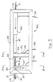
- FIG. 3 Shown in Figures 3, 4, 6 and 7 is apparatus 52 of a first embodiment of the present invention for manufacturing a rock anchor 10.
- apparatus 52 of a first embodiment of the present invention for manufacturing a rock anchor 10.
- the slidable clamp means 22 is held in a carriage 54 slidable along the frame 24.
- the hydraulic ram 28, associated with the fixed clamp means 22' is supplied with hydraulic pressure through a pipe 56.
- the ram 28, associated with the slidable clamp means 22, is supplied with hydraulic pressure through a separate pipe 58.
- a clamp displacement means such as an hydraulic ram 44 is fixed to the right hand end of the frame 24 and has a plunger 45 which bears on the slidable clamp means 22.
- the ram 44 of the displacement means has a separate pipe 60 to supply hydraulic pressure.
- the pipes 56, 58 and 60 are connected to an hydraulic timer (not shown) which co-ordinates the action of both rams 28 and the ram 44.
- the tendon 12 passes through the centre of the ram 44.
- a straight pipe 61 is disposed to the left of the fixed clamp 22 and is arranged to receive the rock anchor 10.
- the pipe 61 has a diameter at least that of the bulb diameter.
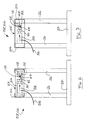
- each plate 30 and 32 has a recess 62.
- the plates 30 and 32 have a centralising pin 64 located below the recesses 62 and extending between the plates 30 and 32.
- the pin 64 serves to support the tendon 12 and to guide the plates 30 and 32 toward one another so that the tendon 12 is clamped within the recesses 62.
- the plate 30 contains a recess (not shown) which receives the pin 64 when the plates 30 and 32 are moved together by the ram 28.
- a tendon 12 is first fed through the ram 44, between the plates 30 and 32, of the clamp means 22 and 22', and into the pipe 61.
- the hydraulic timer operates and activates the ram 28 of the fixed clamping means 22'.
- the ram 28 of the slidable clamp means 22, is then activated to clamp the tendon 12 between the plates 30 and 32.
- the ram 44 is then reactivated. This causes the plunger 45 to bear upon the plates 30 and 32, of the slidable clamp means 22, and displace the slidable clamp means 22 towards the fixed clamp means 22'. Such relative displacement causes the bulbous portions 16 to be formed in the tendon 12 between the clamp means 22 and 22'.
- the ram 28 of the slidable clamp means 22 and the ram 44 are then deactivated to release the tendon 12.
- the ram 44 then withdraws the plunger 45 away from the fixed clamp means 22'. This moves the carriage 54 with the slidable clamp means 22, to the right, away from the fixed clamp means 22'.
- the ram 28, of the slidable clamp means 22 is then activated to clamp the tendon 12 by means of the plates 30 and 32.
- the ram 28 of the fixed clamp means 22' is then deactivated to release the tendon 12.
- the ram 44 is then activated, the plunger 45 extends and moves the carriage 54 and slidable clamp means 22 towards the fixed clamp means 22'.
- the slidable clamp means 22 and the ram 44 function as a tendon displacement means to move the tendon 12.
- This also moves the rock anchor 10 to the left and into the straight pipe 61.
- the pipe 61 generally straightens out any bends that may have occurred when the bulbous portion 16 was formed.
- the ram 44 is then deactivated to prevent any further movement of the tendon 12.
- the ram 28 of the fixed clamping means 22' is then activated and the process is repeated as many times as is required.
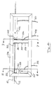
- FIG. 5 and 8 Shown in Figures 5 and 8 is an apparatus 66 of a second embodiment for manufacturing a rock anchor 10.
- This apparatus 66 is a modification of the apparatus 52 of Figures 3, 4, 6 and 7.
- Like numerals denote like parts.
- the apparatus 66 additionally comprises a separate tendon displacement means 68 to the right of the slidable clamp means 22 in Figure 5.
- the tendon displacement means 68 comprises a slidable clamp means 70 carried by a carriage 72 slidable along the frame 24.
- the clamp means 70 comprises an hydraulic ram 74 supplied with hydraulic pressure by a pipe 76.
- the ram 74 has a plate 78 attached thereto to bear on and thereby clamp the tendon 12 against an opposed plate 80.
- Each plate 78 and 80 has a recess 82, in a similar manner to the machine 52 of Figures 3, 4, 6 and 7.
- the plates 78 and 80 have a centralising pin 84 located below the half recesses 82, in a similar manner to the machine 52 of Figures 3, 4, 6 and 7.
- the tendon displacement means 68 further comprises a clamp displacement means in the form of an hydraulic ram 86 supplied with hydraulic pressure through a pipe 88.
- the ram 86 has a plunger 90 which bears on the carriage 72 and is arranged to displace the sliding clamp means 70 to the left, as shown in Figure 5.
- the tendon displacement means 68 is an element supplementary to those comprised by the tendon displacement means of the apparatus 52.
- the pipes 58 and 60 are connected to a common manifold 92 supplied with hydraulic pressure by a pipe 94.
- a pipe 94 supplied with hydraulic pressure by a pipe 94.
- a tendon 12 is first fed through between the plates 78 and 80, through the ram 44, between the plates 30 and 32, of the clamp means 22 and 22' and into the pipe 61.
- An hydraulic timer operates and simultaneously activates both of the rams 28 so that the clamps 22 and 22' securely hold the tendon 12.
- the ram 74 is deactivated to allow the tendon 12 to slide between the plates 78 and 80. Further, at this stage, the clamp means 22 and 22' are a first predetermined distance apart. The ram 44 is then activated to move the carriage 54 to the left, towards the fixed clamp means 22'. This relative displacement disrupts the tendon 12 and forms a bulbous portion 16. When the distance between the clamp means 22 and 22' reaches a second predetermined distance both rams 28 and the ram 44 are deactivated.
- Ram 74 is then activated so that the tendon 12 is securely held in the slidable clamp means 70 by the plates 78 and 80.
- the ram 86 is then activated and the plunger 90 moves the carriage 72 to the left, towards the fixed clamp means 22'. This also moves the rock anchor 10 to the left and into the straight pipe 61.
- the tendon displacement means may alternately comprise an electronic motor driving wheel.
- An idler wheel would bear upon the driven wheel and the tendon would pass between the idler and the driven wheels.
- a timer would activate an electric motor to rotate the driven wheel and thereby move the tendon.
- the ram 44 may have an adjustment means in the form of a threaded column to vary the position of the ram 44 along the frame.
Landscapes
- Engineering & Computer Science (AREA)
- Mining & Mineral Resources (AREA)
- Structural Engineering (AREA)
- Life Sciences & Earth Sciences (AREA)
- General Life Sciences & Earth Sciences (AREA)
- Geochemistry & Mineralogy (AREA)
- Geology (AREA)
- Piles And Underground Anchors (AREA)
- Dowels (AREA)
- Curing Cements, Concrete, And Artificial Stone (AREA)
Claims (11)
- Appareil (52, 66) pour fabriquer une ancre de roche (10), comprenant un élément de précontrainte (12) ayant une multiplicité de torons (14, 15) et au moins une partie bulbiforme (16) dans laquelle tous les torons sont espacés les uns des autres sensiblement sur la périphérie de la partie bulbiforme, l'appareil (52, 66) comprenant une paire de moyens de serrage (22, 22') espacés, disposés chacun pour serrer à l'intérieur l'élément de précontrainte de manière amovible en des positions espacées les unes des autres sur sa longueur et étant montés dans l'appareil pour qu'il y ait une possibilité de déplacement longitudinal relatif entre les moyens de serrage (22, 22'), et un moyen de déplacement de moyen de serrage (44) pour déplacer un moyen de serrage vers l'autre afin de former une partie bulbiforme (16) dans l'élément de précontrainte (12) entre les deux moyens de serrage, caractérisé en ce que l'appareil comprend aussi un moyen de déplacement d'élément de précontrainte (44, 68) pour déplacer l'élément de précontrainte (12) dans sa direction longitudinale par rapport aux moyens de serrage après qu'une partie bulbiforme (16) a été formée dans l'élément de précontrainte, comprenant un moyen de serrage (22 ; 70) disposé de manière amovible pour saisir l'élément de précontrainte (12).
- Appareil (52, 66) selon la revendication 1, caractérisé en ce que le moyen de serrage (22) du moyen de déplacement d'élément de précontrainte (44) est un moyen de serrage (22) de ladite paire de moyens de serrage (22, 22').
- Appareil (66) selon la revendication 1, caractérisé en ce que le moyen de serrage du moyen de déplacement d'élément de précontrainte (68) est un moyen de serrage (70) additionnel à la dite paire de moyens de serrage (22, 22') espacés et disposé pour saisir l'élément de précontrainte (12) lorsque les deux moyens de serrage de ladite paire de moyens de serrage (22, 22') espacés n'agissent pas sur l'élément de précontrainte.
- Appareil (52, 66) selon la revendication 1, 2 ou 3, caractérisé en ce qu'un seul élément de serrage (22) de ladite paire d'éléments de serrage (22, 22') est déplaçable dans ladite direction longitudinale.
- Appareil (52, 66) selon l'une quelconque des revendications précédentes, caractérisé en ce que le moyen de serrage (22, 70) du moyen de déplacement d'élément de précontrainte (44, 68) est déplaçable par un moyen à vérin hydraulique (44, 86).
- Appareil (52, 66) selon la revendication 2, 3, 4 ou 5, caractérisé en ce que le moyen de serrage déplaçable (22) est porté dans un chariot (54) qui peut coulisser le long d'un cadre (24) de l'appareil.
- Appareil (52, 66) selon l'une quelconque des revendications précédentes, caractérisé en ce que chaque moyen de serrage comporte une paire de plaques opposées (30, 32 ; 78, 80) et un moyen à vérin hydraulique (28 ; 74) portant sur l'une (30 ; 78) desdites plaques pour l'amener en opposition contre l'autre (32 ; 80) desdites plaques.
- Appareil (52, 66) selon l'une quelconque des revendications 1 à 7, caractérisé en ce que chaque moyen de serrage (22, 22' ; 70) comporte une plaque (30, 32 ; 78, 80) munie d'un évidement (62 ; 82) conçu pour recevoir l'élément de précontrainte (12).
- Appareil (52, 66) selon la revendication 8, caractérisé en ce qu'une tige de centrage (64 ; 84) est associée aux plaques (30, 32 ; 78, 80) des moyens de serrage (22, 22' ; 70) pour soutenir l'élément de précontrainte (12) et pour guider l'un vers l'autre les évidements (62 ; 82) des plaques (30, 32 ; 78, 80).
- Appareil (52, 66) selon l'une quelconque des revendications 1 à 9, caractérisé en ce que le moyen de déplacement de moyen de serrage est actionnable pour écarter ladite paire de moyens de serrage (22, 22') d'une première distance prédéterminée avant la formation de la partie bulbiforme (16) et d'une seconde distance prédéterminée après la formation de la partie bulbiforme (16).
- Appareil (52, 66) selon l'une quelconque des revendications 1 à 10, caractérisé en ce qu'un tube sensiblement rectiligne (61) est prévu pour recevoir et sensiblement pour redresser l'ancre de roche (10) lorsqu'elle émerge des moyens de serrage (22, 22') après la formation de la partie bulbiforme (16).
Applications Claiming Priority (3)
| Application Number | Priority Date | Filing Date | Title |
|---|---|---|---|
| AU1416/88 | 1988-11-14 | ||
| AUPJ141688 | 1988-11-14 | ||
| PCT/AU1989/000486 WO1990005811A1 (fr) | 1988-11-14 | 1989-11-14 | Ancre de roche amelioree et procede de fabrication |
Publications (3)
| Publication Number | Publication Date |
|---|---|
| EP0442935A1 EP0442935A1 (fr) | 1991-08-28 |
| EP0442935A4 EP0442935A4 (en) | 1992-06-03 |
| EP0442935B1 true EP0442935B1 (fr) | 1995-09-06 |
Family
ID=3773499
Family Applications (1)
| Application Number | Title | Priority Date | Filing Date |
|---|---|---|---|
| EP89912755A Expired - Lifetime EP0442935B1 (fr) | 1988-11-14 | 1989-11-14 | Ancre de roche amelioree et procede de fabrication |
Country Status (6)
| Country | Link |
|---|---|
| EP (1) | EP0442935B1 (fr) |
| AT (1) | ATE127550T1 (fr) |
| CA (1) | CA2002806C (fr) |
| DE (1) | DE68924171T2 (fr) |
| WO (1) | WO1990005811A1 (fr) |
| ZA (1) | ZA898640B (fr) |
Families Citing this family (7)
| Publication number | Priority date | Publication date | Assignee | Title |
|---|---|---|---|---|
| EP0595966B1 (fr) * | 1991-07-26 | 1999-10-13 | J.J.P. Geotechnical Engineering Pty. Ltd. | Cheville de fixation en forme de cable |
| DE4203740C2 (de) * | 1992-02-09 | 1996-07-11 | Dyckerhoff & Widmann Ag | Verfahren zum Herstellen eines Ankerelementes aus einer Litze aus verdrillten Stahldrähten |
| FR2726585A1 (fr) * | 1994-11-09 | 1996-05-10 | Fortin Jean | Moyen d'ancrage d'un surmoulage plastique ou autre sur du cable |
| AU2005200714B2 (en) * | 2005-02-17 | 2011-10-27 | Fci Holdings Delaware, Inc. | Cable bulbing apparatus and method for forming bulbs in a cable bolt |
| KR101043127B1 (ko) * | 2008-02-22 | 2011-06-20 | (주) 케이씨지 | Pc강연선을 이용한 지반보강공법 및 지반보강장치 |
| WO2011047416A1 (fr) * | 2009-10-23 | 2011-04-28 | Garford Pty Ltd | Câble d'ancrage |
| CN111842722B (zh) * | 2020-08-30 | 2024-08-27 | 尤加东 | 一种钢绞线墩头 |
Family Cites Families (13)
| Publication number | Priority date | Publication date | Assignee | Title |
|---|---|---|---|---|
| GB1024696A (en) * | 1962-10-26 | 1966-03-30 | Cementation Co Ltd | Improvements relating to subterranean anchorages |
| GB975642A (en) * | 1962-11-12 | 1964-11-18 | Cementation Co Ltd | Improvements relating to subterranean anchorages |
| US3727298A (en) * | 1971-06-10 | 1973-04-17 | North American Rockwell | Friction welding method |
| FR2378123A1 (fr) * | 1977-01-24 | 1978-08-18 | Bouvet Ets H | Procede de fabrication d'une bequille metallique pour serrure et dispositif pour la mise en oeuvre du procede |
| FR2385485A1 (fr) * | 1977-03-30 | 1978-10-27 | Petroles Cie Francaise | Machine d'aboutage de conduites pour pose en eaux de toutes profondeurs |
| CA1059351A (fr) * | 1977-11-01 | 1979-07-31 | Paul J. Villgren | Boulon pour cable |
| CH632948A5 (de) * | 1978-11-10 | 1982-11-15 | Schlatter Ag | Einrichtung zum stirnseitigen aneinanderschweissen zweier profilstangen. |
| AU7976382A (en) * | 1981-01-27 | 1982-08-05 | Barry Garfield Frederick | Pipe joining apparatus |
| US4492015A (en) * | 1982-06-24 | 1985-01-08 | Dearman Timothy Charles | Apparatus for use in welding |
| US4722468A (en) * | 1982-07-20 | 1988-02-02 | Mcclure Gary W | Boiler pipe tool for heliarc welding with tongue and groove interlock |
| GB8321550D0 (en) * | 1983-08-10 | 1983-09-14 | Dividag Systems Ltd | Anchor |
| FR2571996B1 (fr) * | 1984-10-22 | 1986-12-26 | Alsthom Atlantique | Dispositif exterieur d'aboutage de deux elements tubulaires en vue de leur assemblage par soudage |
| US4750662A (en) * | 1987-02-10 | 1988-06-14 | Larry And Associates | Pipe welding alignment tool |
-
1989
- 1989-11-10 CA CA002002806A patent/CA2002806C/fr not_active Expired - Lifetime
- 1989-11-13 ZA ZA898640A patent/ZA898640B/xx unknown
- 1989-11-14 DE DE68924171T patent/DE68924171T2/de not_active Expired - Fee Related
- 1989-11-14 WO PCT/AU1989/000486 patent/WO1990005811A1/fr not_active Ceased
- 1989-11-14 AT AT89912755T patent/ATE127550T1/de not_active IP Right Cessation
- 1989-11-14 EP EP89912755A patent/EP0442935B1/fr not_active Expired - Lifetime
Also Published As
| Publication number | Publication date |
|---|---|
| ATE127550T1 (de) | 1995-09-15 |
| WO1990005811A1 (fr) | 1990-05-31 |
| DE68924171T2 (de) | 1996-02-22 |
| EP0442935A1 (fr) | 1991-08-28 |
| CA2002806F (fr) | 1990-05-14 |
| ZA898640B (en) | 1990-09-26 |
| CA2002806A1 (en) | 1990-05-14 |
| EP0442935A4 (en) | 1992-06-03 |
| DE68924171D1 (de) | 1995-10-12 |
| CA2002806C (fr) | 1995-08-08 |
Similar Documents
| Publication | Publication Date | Title |
|---|---|---|
| US5344256A (en) | Rock anchor and method of manufacture | |
| EP0467560B1 (fr) | Procédé et dispositif pour former une feuille de caoutchouc renforcée par des cordes | |
| EP0442935B1 (fr) | Ancre de roche amelioree et procede de fabrication | |
| EP1707684B1 (fr) | Procédé et dispositif pour tendre d'un ancrage étagé | |
| US3921281A (en) | Method for joining steel bars | |
| CA2089038C (fr) | Methode de fabrication d'un element d'ancrage a partir d'un toron de fils d'acier | |
| RU2687981C1 (ru) | Способ счалки каната | |
| US2166847A (en) | Wire clamp | |
| US3762196A (en) | Pipe bending machine | |
| CA2027540A1 (fr) | Methode de soudage a froid, par pression, et machine permettant de mettre en oeuvre ladite methode | |
| US7458242B2 (en) | Apparatus and method for manufacturing a rock bolt | |
| AU640906C (en) | Improved rock anchor and method of manufacture | |
| US5058469A (en) | Cable shear and clamp system | |
| EP1015162B1 (fr) | Procede et dispositif pour joindre des composants | |
| CA1245919A (fr) | Methode et materiel de fabrication de cables toronnes | |
| US3882585A (en) | Method and device for positioning prestressing hoops | |
| CN1009714B (zh) | 在无端头的薄壁金属套张紧在滚筒上的方法和装置 | |
| AU4621589A (en) | Improved rock anchor and method of manufacture | |
| US4741794A (en) | Equipment for the manufacture of mainly large-diameter flexible hoses having spiralled reinforcement | |
| EP0790871B1 (fr) | Procede et appareil de fabrication de produits helicoidaux | |
| EP0351465B1 (fr) | Fer d'ancrage | |
| JPH06317020A (ja) | 緊張材の中間定着装置 | |
| US3831243A (en) | Method for making self-centering pulleys | |
| JPH04108750U (ja) | 非金属製緊張材用定着具 | |
| US3633265A (en) | Method of securing spiral-lay wire ropes in tapered socket |
Legal Events
| Date | Code | Title | Description |
|---|---|---|---|
| PUAI | Public reference made under article 153(3) epc to a published international application that has entered the european phase |
Free format text: ORIGINAL CODE: 0009012 |
|
| 17P | Request for examination filed |
Effective date: 19910514 |
|
| AK | Designated contracting states |
Kind code of ref document: A1 Designated state(s): AT BE CH DE FR GB IT LI LU NL SE |
|
| A4 | Supplementary search report drawn up and despatched |
Effective date: 19920416 |
|
| AK | Designated contracting states |
Kind code of ref document: A4 Designated state(s): AT BE CH DE FR GB IT LI LU NL SE |
|
| 17Q | First examination report despatched |
Effective date: 19940316 |
|
| GRAA | (expected) grant |
Free format text: ORIGINAL CODE: 0009210 |
|
| AK | Designated contracting states |
Kind code of ref document: B1 Designated state(s): AT BE CH DE FR GB IT LI LU NL SE |
|
| PG25 | Lapsed in a contracting state [announced via postgrant information from national office to epo] |
Ref country code: AT Effective date: 19950906 Ref country code: BE Effective date: 19950906 Ref country code: NL Free format text: LAPSE BECAUSE OF NON-PAYMENT OF DUE FEES Effective date: 19950906 Ref country code: FR Effective date: 19950906 |
|
| REF | Corresponds to: |
Ref document number: 127550 Country of ref document: AT Date of ref document: 19950915 Kind code of ref document: T |
|
| REF | Corresponds to: |
Ref document number: 68924171 Country of ref document: DE Date of ref document: 19951012 |
|
| ITF | It: translation for a ep patent filed | ||
| PG25 | Lapsed in a contracting state [announced via postgrant information from national office to epo] |
Ref country code: LU Free format text: LAPSE BECAUSE OF NON-PAYMENT OF DUE FEES Effective date: 19951130 |
|
| PGFP | Annual fee paid to national office [announced via postgrant information from national office to epo] |
Ref country code: CH Payment date: 19951130 Year of fee payment: 7 |
|
| NLV1 | Nl: lapsed or annulled due to failure to fulfill the requirements of art. 29p and 29m of the patents act | ||
| EN | Fr: translation not filed | ||
| REG | Reference to a national code |
Ref country code: CH Ref legal event code: PL |
|
| PLBE | No opposition filed within time limit |
Free format text: ORIGINAL CODE: 0009261 |
|
| STAA | Information on the status of an ep patent application or granted ep patent |
Free format text: STATUS: NO OPPOSITION FILED WITHIN TIME LIMIT |
|
| 26N | No opposition filed | ||
| PG25 | Lapsed in a contracting state [announced via postgrant information from national office to epo] |
Ref country code: LI Free format text: LAPSE BECAUSE OF FAILURE TO SUBMIT A TRANSLATION OF THE DESCRIPTION OR TO PAY THE FEE WITHIN THE PRESCRIBED TIME-LIMIT Effective date: 19961130 Ref country code: CH Free format text: LAPSE BECAUSE OF FAILURE TO SUBMIT A TRANSLATION OF THE DESCRIPTION OR TO PAY THE FEE WITHIN THE PRESCRIBED TIME-LIMIT Effective date: 19961130 |
|
| REG | Reference to a national code |
Ref country code: GB Ref legal event code: IF02 |
|
| PGFP | Annual fee paid to national office [announced via postgrant information from national office to epo] |
Ref country code: DE Payment date: 20031105 Year of fee payment: 15 |
|
| PG25 | Lapsed in a contracting state [announced via postgrant information from national office to epo] |
Ref country code: DE Free format text: LAPSE BECAUSE OF NON-PAYMENT OF DUE FEES Effective date: 20050601 |
|
| PG25 | Lapsed in a contracting state [announced via postgrant information from national office to epo] |
Ref country code: IT Free format text: LAPSE BECAUSE OF NON-PAYMENT OF DUE FEES;WARNING: LAPSES OF ITALIAN PATENTS WITH EFFECTIVE DATE BEFORE 2007 MAY HAVE OCCURRED AT ANY TIME BEFORE 2007. THE CORRECT EFFECTIVE DATE MAY BE DIFFERENT FROM THE ONE RECORDED. Effective date: 20051114 |
|
| PGFP | Annual fee paid to national office [announced via postgrant information from national office to epo] |
Ref country code: SE Payment date: 20081107 Year of fee payment: 20 |
|
| PGFP | Annual fee paid to national office [announced via postgrant information from national office to epo] |
Ref country code: GB Payment date: 20081127 Year of fee payment: 20 |
|
| REG | Reference to a national code |
Ref country code: GB Ref legal event code: PE20 Expiry date: 20091113 |
|
| PG25 | Lapsed in a contracting state [announced via postgrant information from national office to epo] |
Ref country code: GB Free format text: LAPSE BECAUSE OF EXPIRATION OF PROTECTION Effective date: 20091113 |